U.S. Department of Transportation
Federal Highway Administration
1200 New Jersey Avenue, SE
Washington, DC 20590
202-366-4000
Federal Highway Administration Research and Technology
Coordinating, Developing, and Delivering Highway Transportation Innovations
 |
| This report is an archived publication and may contain dated technical, contact, and link information |
|
Publication Number: FHWA-HRT-07-024
Date: February 2007 |
|||
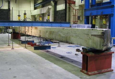
Flexural Capacity of Fire-Damaged Prestressed Concrete Box BeamsCHAPTER 2. EXPERIMENTAL PROGRAM2.1 IntroductionThe primary emphasis of the test program was to determine the ultimate flexural capacity of the box beams in the bridge. The four beams came from different parts of the bridge and were likely subjected to varying levels of fire intensity. As such, the test matrix was designed to subject the four beams to identical loading conditions from test initiation through flexural failure. Prior to flexural testing the beams were visually surveyed for damage relating to the fire. After flexural testing, portions of the bottoms of the beams undamaged by the flexure tests were more thoroughly investigated through coring, visual inspection, and petrographic examination. 2.2 Flexure Test Setup and InstrumentationThe setup for the flexure tests was designed to create a constant moment region at midspan of the beam. The beams were tested on a 14.1 m (46 ft 4 inches) span with two point loads applied 0.91 m (3 ft) on either side of midspan. The beams were supported at both ends by a 200-mm- (8-inch-) wide steel plate that rested on a roller bearing. The loads were applied to each beam through a 300-mm- (12-inch-) wide steel plate that spanned the width of the beam and was grouted to the top flange. Figure 3 is a photograph showing the test setup for the flexural loading of these box beams.
Figure 3. Photo. Flexural loading of a box beam
The four beams had the same nominal midspan cross section as shown in Figure 4. The 0.64-m- (25-inch-) deep, 0.91-m- (36-inch-) wide box beams each contained two 0.305-m-(12-inch-) diameter circular voids located 0.32 m (12.5 inches) down from the top of the beam. The voids were formed with cardboard tubes that were capped at the quarter points and at midspan to allow for a continuous diaphragm across the bridge. Each beam was prestressed with thirty-six 9.5-mm- (0.375-inch-) diameter prestressing strands in the bottom flange, and two of these same strands in the top flange. Two number 4 rebars were also located in the top flange, serving to aid in installation of the mild steel reinforcement shear stirrups.
After failure of each beam at the midspan cross section, this cross section was examined to determine as-built dimensions. It must be noted that the likely intended cross-sectional dimensions are shown in Figure 4, but that the actual as-built dimensions varied. For instance, the total minimum web thickness at middepth of the voids is 0.305 m (12 inches). At this location, the distance from a particular void to the outside face of the beam varied amongst the beams from a low of 51 mm (2 inches) in one beam to a high of 152 mm (6 inches) in another beam. Additionally, note that the distance from the bottom flange to the center of the bottom row of prestressing strands ranged from 38 to 51 mm (1.5 to 2.0 inches) throughout the beams. The instrumentation plan implemented on each of the four tests included load cells, strain gages, and linear string potentiometers. Four load cells measured the load applied to the beam through the pair of hydraulic jacks located at each of the two load points. Eleven resistance strain gages (120 ohm resistance, 51 mm- (2 inch-) gage length) were applied to the midspan cross section of each of the beams. Three of these gages were applied to the top of the beam, with one on the midline and the other two located symmetrically 330 mm (13 inches) from the midline. The other eight gages were affixed to the north and south elevations of the beam, with gages located 102, 203, 305, 406 mm (4, 8, 12, and 16 inches) down from the top of the beam on each face. All strain gages measured longitudinal strain in the beam. Finally, seven string potentiometers were attached to the midline of the bottom of each beam to measure vertical deflections. The potentiometers were placed at midspan and symmetrically about the midspan at 0.91, 2.74, and 4.57 m (3, 9, and 15 ft) east and west of midspan. These 22 instruments were read continuously throughout the test, and their readings were saved periodically at each load and/or displacement step.
|