U.S. Department of Transportation
Federal Highway Administration
1200 New Jersey Avenue, SE
Washington, DC 20590
202-366-4000
Federal Highway Administration Research and Technology
Coordinating, Developing, and Delivering Highway Transportation Innovations
 |
| This report is an archived publication and may contain dated technical, contact, and link information |
|
Publication Number: FHWA-RD-99-194
Date: June 2000 |
||||||||||||||||||||||||||||||||||||||||||||||||||||||||||
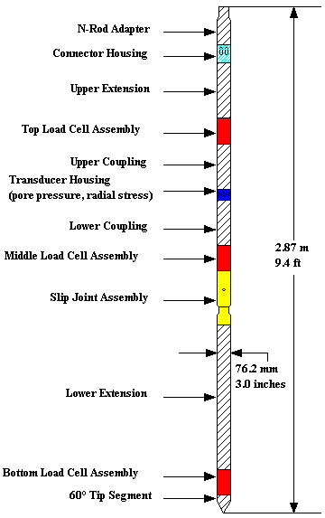
Development and Field Testing of Multiple Deployment Model Pile (MDMP)CHAPTER 8. SUMMARY CONCLUSIONS AND RECOMMENDATIONS8.1 Summary8.1.1 The MDMP Configuration and SpecificationsThe Multiple Deployment Model Pile (MDMP) is an in situ soil testing device composed of a series of modular sensors that can be assembled in various desired configurations. The MDMP can be either pushed or driven to the required testing depth, typically beyond the bottom of a cased borehole. The model pile is capable of measuring axial loads, pore water pressure, total radial stresses, local displacement, and pile acceleration. A typical configuration of the modular MDMP is shown in Figure 127. The MDMP instrumentation includes three load cells, three accelerometers, a displacement transducer, a pore pressure transducer, and a total pressure cell. The friction sleeve between the top and middle load cells is 83.5 cm (32.9 in) long and constitutes a surface area of 2000 cm2 (310 in2). Table 47 summarizes the ranges of the MDMP instrumentation. 8.1.2 The Newbury Site TestingThe first field deployment of theMDMP was at a site located in Newbury, Massachusetts during March 1996. The test location was chosen because it contained a 9- to 12-m- (30- to 40-ft-) thick clay deposit close to the ground surface, allowing to assess the pile capacity gain and pore pressure dissipation with time. Additional full-scale instrumented pile testing was also carried out at the same location. Table 47. Summary of the MDMP Instrumentation Ranges.
On March 6, 1996, the first of two model pile tests was conducted at the Newbury Site. The pile was driven about 9.33 m (30.6 ft) below ground surface, with the pressure cell and friction sleeve at a depth of 7.39 m (24.25 ft). An initial load test was performed in compression, followed by 11 load tests with time performed in tension. A final static-cyclic load test in compression was performed about 138 h after pile installation.
Figure 127. Typical Configuration of the Modular MDMP. On March 13, 1996, the second of the two model pile tests was conducted at the Newbury Site. The pile was driven about 12.31 m (40.4 ft) below ground surface, with the pressure cell and friction sleeve at a depth of 10.46 m (34.33 ft). An initial load test was performed in compression, followed by nine load tests with time performed in tension. A final static-cyclic load test in compression was performed about 120 h after pile installation. In both tests, the MDMP was monitored with the Pile Driving Analyzer (PDA) during installation and a restrike following the static load tests. When the pile was extracted (after the completion of each testing series), it was surrounded by a soil cake conforming to the 101.6-mm (4-in) casing, indicating that the shear in the soil had taken place some distance away from the pile wall. 8.1.3 Test Results(1) Pore Pressure Dissipation. The hydrostatic pressure was established to be 57.02 kPa and 87.43 kPa for the NB2 and NB3 testing depths, respectively. The initial (peak) and final measured pore water pressures during test NB2 were 217.3 kPa and 51.02 kPa, respectively. The initial and final measured pore water pressures during test NB3 were 224.0 kPa and 92.46 kPa, respectively. Using the methodology presented by Paikowsky et al. (1995), the rate of pore pressure dissipation, Hut, was found to be 0.6047 and 0.6011 for NB2 and NB3, respectively. The time at 50% dissipation, t50, for NB2 was 9.854 h (35476 s) and for NB3, it was 7.849 h (28256 s). When adjusted to the PLS Cell radius (19.177 mm), t50(pls) was 2.493 h (8975 s) and 1.986 h (7149 s) for NB2 and NB3, respectively. (2) Capacity Gain. A compression load test was carried out 25 min after the installation of MDMP test NB2 in which a skin resistance of 0.16 kN (35 lb) was measured along the frictional sleeve (equivalent to a shear stress of 0.78 kPa (0.11 psi)). The final pull-out test (11th in the sequence) was conducted 118.6 h after the end of installation in which a skin resistance of 5.54 kN (1246.5 lb) was measured along the frictional sleeve (equivalent to a shear stress of 27.72 kPa (4.02 psi)). A compression load test was carried out 21.5 min after the installation of MDMP test NB3 in which a skin resistance of 0.23 kN (51 lb) was measured along the frictional sleeve (equivalent to a shear stress of 1.13 kPa (0.16 psi)). The final pull-out test (9th in the sequence) was conducted 94.9 h after the end of installation in which a skin resistance of 4.67 kN (1,050 lb) was measured along the frictional sleeve (equivalent to a shear stress of 23.35 kPa (3.39 psi)). Using the methodology presented by Paikowsky et al. (1995), the rate of capacity gain (Cgt) for both peak values and residual values measured during NB2 was 0.589. MDMP test NB3 resulted in a rate of capacity gain (Cgt) of 0.599 for peak values and 0.631 for residual values. The time to 75% gain of capacity, t75, for NB2 was 67.7 h for peak values and 70.7 h for residual values, and for NB3, t75 was 43.2 h for peak values and 38.2 h for residual values. Following the standard normalization used by Paikowsky et al. (1995), t75 was adjusted to a 152.4-mm (6-in) radius pile. The t75(152.4 mm) was 1083.2 h for peak values and 1131.2 h for residual values, and 691.2 h for peak values and 610.9 h for residual values for NB2 and NB3, respectively. (3) Radial Consolidation. The coefficients of
horizontal consolidation, ch, were 0.0135 cm2/s and
0.0170 cm2/s for NB2 and NB3, respectively. (4) Radial Stresses. The total radial stresses were measured to be similar to the magnitude of the pore pressures at the end of the MDMP installation (200 kPa for NB2). The total radial stresses then gradually decreased at a rate somewhat lower than the pore pressure dissipation, which resulted in a slow increase in the effective radial stresses. This increase was at a rate of 1.52 kPa/h beginning about 1 h after the end of the driving, and reached about 36 kPa 37 h later. At that point, the total radial stress was about equal to the total vertical stress. At the same time, the consolidation process was at about 90% and a sharp increase was observed in the radial total and effective stresses. The radial stresses seemed to stabilize about 67 h after the end of the MDMP NB2 installation and remained about constant thereafter, affected only by the load testing. (5) Static - Cyclic Load Tests. A test consisting of a large displacement (about 50 mm) downward, following by a static-cyclic full-mobilization load test completed the final testing of MDMP tests NB2 and NB3. The frictional behavior presented degradation with the displacement and repetitive behavior in the loading-unloading cycle of the testing. The peak forces along the friction sleeve in the push tests were 2.61 kN (588 lb) and 1.17 kN (263 lb). (6) Dynamic Analysis. Multiple dynamic measurements were carried out at the top of the drilling rods and inside the MDMP. The analysis of the measurements, while allowing insight for the behavior, encountered some difficulties due to the complexity of the pile geometry. 8.2 Conclusions8.2.1 General Conclusions
8.2.2 Major Conclusions
8.2.3 Detailed Conclusions
8.3 Recommendations
|