U.S. Department of Transportation
Federal Highway Administration
1200 New Jersey Avenue, SE
Washington, DC 20590
202-366-4000
Federal Highway Administration Research and Technology
Coordinating, Developing, and Delivering Highway Transportation Innovations
 |
| This report is an archived publication and may contain dated technical, contact, and link information |
|
Publication Number: FHWA-HRT-10-037
Date: October 2010 |
||||||||||||||||||||||||||||||||||||||||||||||||||||||||
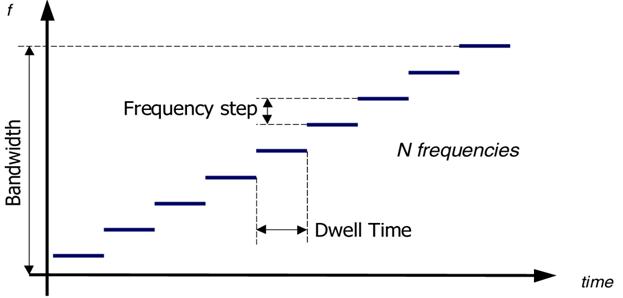
Step Frequency Ground Penetrating Radar Characterization and Federal Evaluation TestsBackgroundThis section provides a brief description of SF GPR technology, system emission characteristics, and emissions limits under NTIA rules. Capabilities of FHWA/USDOT SF GPR are made possible by efficient techniques used to transmit and receive radar energy and subsequently store and process the corresponding data. Proposed SF GPR output signal characteristics are presented in figure 1.
SF GPR signal output consists of continuous sine waves transmitted at a series of discrete frequencies during programmed dwell times. Frequency domain data collected by the receiver antenna are subsequently transformed into the time domain for display as range profiles and are later processed with data from many antenna array elements to produce tomographic images. In order to accurately image subsurface defect and deterioration features such as cracks and voids in concrete, asphalt, and other civil engineering materials, SF GPR must have high range resolution and cross-range resolution capabilities. SF GPR resolution is directly dependent on the operating bandwidth of the system. Broad frequency availability is necessary to achieve the high resolution required to image features such as cracks, voids, and reinforcing steel. Operating parameters of the SF GPR system under test include the following:
Emissions MaskProviding adequate bandwidth to accurately image features such as subsurface cracks, voids, and reinforcing steel is anticipated to require a system that complies with the recommended emission mask presented in table 1 and table 2. The tables specify maximum back lobe emissions because SF GPR equipment is operated with the antenna directed at the ground; unintentional emissions into the air will always be back lobe emissions. For instances where an SF GPR was used on a bridge deck that vehicles traveled under, calculations were made to determine the attenuation of the radar energy that propagated through the bridge deck. The internal report Step Frequency GPR (SF GPR) Transmission Loss Calculations Through a Typical Concrete Bridge Deck (SPS-16371/1) provides transmission loss calculations for a typical concrete bridge deck, showing that emissions transmitted through the bridge deck are reduced below back lobe emission levels (see appendix F).
In addition to the radiated emission limits specified in table 1, SF GPR was programmed to suppress emissions according to the limits in table 2.
In addition to the recommended emissions mask in table 1 and table 2, notches that may be implemented in the recommended SF GPR emissions mask are summarized in table 3 through table 5. These notches correspond to frequencies of critical Federal systems that the NTIA SPS requested to include in SF GPR emissions testing. These frequencies are candidates for notching from the SF GPR emissions spectrum. One notch configuration, A1, was tested during initial testing, and all three notch configurations, A1, A2, and A3, were tested during follow-up testing. Regarding the practical implementation of notching configurations, they were accomplished by not transmitting at specific frequencies in the SF sequence (always generated sequentially within the SF GPR system). Therefore, the cycle time of the system remained constant for notched and unnotched configurations.
|