U.S. Department of Transportation
Federal Highway Administration
1200 New Jersey Avenue, SE
Washington, DC 20590
202-366-4000
Federal Highway Administration Research and Technology
Coordinating, Developing, and Delivering Highway Transportation Innovations
 |
| This report is an archived publication and may contain dated technical, contact, and link information |
|
Publication Number: FHWA-HRT-06-139
Date: October 2006 |
The inductive-loop detector system is composed of one or more wire loops embedded in the pavement (the sensing element), a splice between the lead-in wire and the lead-in cable in the pull box, lead-in cable (usually in a conduit) connecting to the terminal strip in the controller cabinet, cable from the terminal strip to the inductive-loop electronics unit, and finally, the electronics unit, itself. The interconnections among these various components are illustrated in Figure 5-1.
Figure 5-1. Inductive-loop detector system configuration.
The paragraphs below describe the installation of inductive-loop detectors, beginning with an overview and followed by detailed discussions of failure mechanisms associated with poor installation, common installation techniques and materials, and alternative installation techniques.
Inductive-loop detectors are installed in asphalt or portland cement concrete pavements using the process illustrated in Figures 5-2 through 5-7 and described by the steps below:
Installation techniques differ in the treatment of the corners where two saw cuts intersect, splicing techniques, sealant types, and sealant application. Guidelines and recommendations to assist highway maintenance agencies and other related organizations in planning and installing inductive-loop detectors are found in this chapter and other FHWA reports.(1)
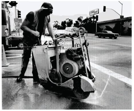
Figure 5-2. Loop sawcut process.
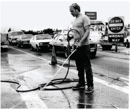
Figure 5-3. Pavement washing.
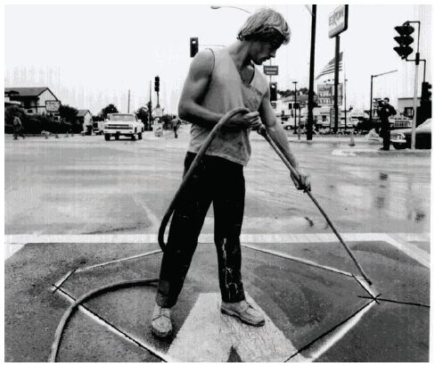
Figure 5-4. Pavement blow drying.
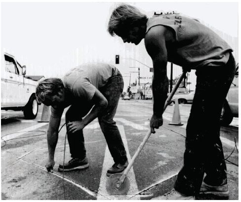
Figure 5-5. Pressing in wire and backer rod.
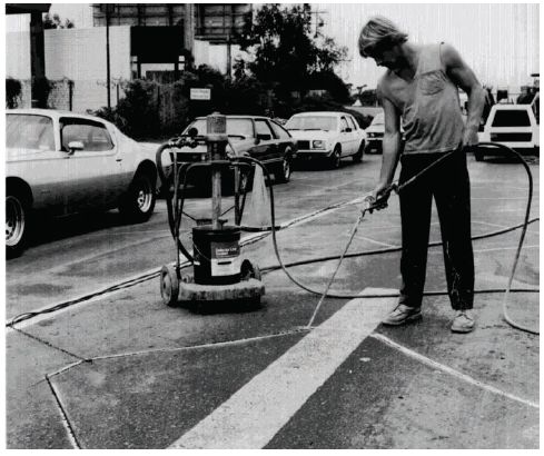
Figure 5-6. Inserting loop sealant.
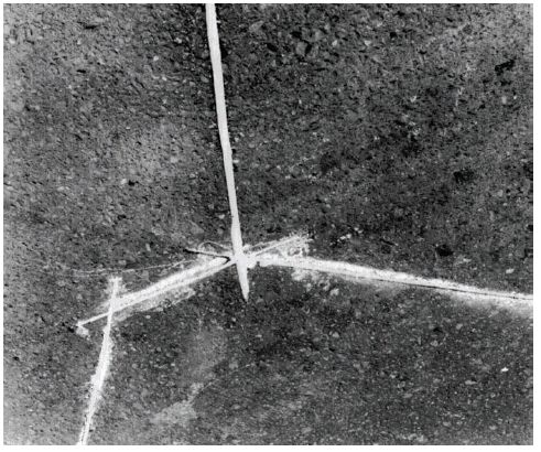
Figure 5-7. Detail of final inductive-loop installation.
Installation techniques and theories vary widely among traffic agencies as shown, for example, in the survey of western State practices exhibited in Table 5-3.(2,3) Procedures developed over time frequently become outdated or are no longer effective; yet there is often great resistance to change. In many cases, contractors perform sensor installation using proprietary shortcuts (and shortcomings). The importance of appropriate installation procedures for long-term operational effectiveness of sensors cannot be overstressed. Since contractors primarily install inductive-loop detectors, it follows that construction supervision and inspection by the responsible agency is critical to their proper operation and reduced maintenance.
| State | Loop type | Sawcut dimensions | Cleaning method | Loop wire | Lead-in cable | Electronics unit mounting |
|---|---|---|---|---|---|---|
Alaska |
6 x 6 ft square (3 turns) 6 x 20 ft (2 turns) | – | – | #14 THNN stranded | IMSA 50-2 or #12 twisted pair w/ shield and drain | Shelf |
California |
6 x 6 ft square or diamond (3 turns) 6 x 6–50ft quadrupole (2-4-2 or 1-2-1) | W = 1 / 4 to 1 / 2 inches (6.4-12.7 mm) D = 1-3/4 inches (44.5 mm) | Flush with water and blow out and dry with air | #12 RHW Use neoprene or x-link polyethylene stranded | 2 #12 solid unshielded 2 #14 or #16 stranded, shielded; 4 #18 stranded, shielded | Rack |
Idaho |
6 x 6 ft square (2 turns) | W=3/8 inch (9.5 mm); D = 1-1/2 inches (38.1 mm) min. | Blow out with air | Model 20002 vehicle homerun cable (4 #18 conductors) | Belden 8227 | Rack |
Montana |
6 x 6 ft square 6 x 20 ft quadrupole (various numbers of turns) | Asphalt: W = 1/4 inch (6.4 mm); D =2 inches (50.8 mm); Concrete: W = 1/4 inch (6.4 mm); D = 11/4 inches (31.8 mm) | Blow out with air | #12 XHHN stranded | Belden 8720 | Shelf |
Nevada |
6 x 6 ft square (3 turns) 6 x 25 ft rectangle (2 turns) 6 x 70 ft rectangle (1 turn) 6x 75 ft quadrupole (1-2-1) | W= 1/4 inch (6.4 mm); D = 2 inches (50.8 mm) | Blow out with air | #12 RHW and XHHW N. Nevadasolid S. Nevada stranded | IMSA 19-2 (pair communication cable with shield) | Mostly shelf |
Oregon | Single loop – 4 x 4 ft diamond Series of loops – 3 x 3ft diamonds (both4 turns) | W= 1/4 inch (6.4 mm); D = 2 inches (50.8 mm) | Flush with water and blow out with air | #14 THWN stranded | IMSA 50-2, Belden 8720,or equivalent | Rack |
Utah | 6 x 6 ft square (3 turns) 6 x 16 ft rectangle (3 turns) 6 x >16 ft rectangle (2 turns) | W= 1/4 inch (6.4 mm); D = 2 inches (50.8 mm) | Blow out with air | #14 THHN or THNN stranded | Belden 8720 or equivalent | Shelf |
Washington | 6 x 6 ft square (4 turns) 6x 50 ft quadrupole (2-4-2) | W= 1/4 inch (6.4 mm); D = 2 1/2 to 3 inches (38.1 to 63.5 mm) inches | Blow out with air | #14 XLP, RHH, or RHW or #12 XLP stranded | AIW 7311 or Belden 8718 | Shelf and rack |
| 1 ft = 0.3 m; W = width; D = depth |
Newer inductive-loop detector installations are even more varied. Because of the high failure rates attributed to moisture or breaks in wire, the trend is to encase and seal the loop wires in a protective covering prior to sealing the sawcut. Some agencies choose to prewind and bundle the loops in the shop to ensure the proper number of turns and to reduce street installation time. Other agencies preform the loops (i.e., the loop consists of 1/2- or 3/4-inch (12- or 19-mm) polyvinyl chloride (PVC) pipe with the wire enclosed). These loops require at least a 1-inch (25-mm) wide slot in the pavement rather than the narrow sawcut used for conventional loops. Another technique utilizes wider slots of up to 4 inches (100 mm) to facilitate placement of the preformed loop.
Because of harsh weather, Alaska enhances loop protection with their preformed loop. The loop is enclosed in 1-inch (25-mm) Schedule 40 PVC pipe (instead of Schedule 80). The loop wire is #12 AWG crosslinked polyethylene with backer rod fill to prevent damage caused by water encroachment and eventual freezing.
In addition, many inductive-loop detectors are now built into the pavement during construction of a new roadway or during repaving. In Puerto Rico, concrete slabs with the inductive-loop detectors in place are being installed (see later discussion under “Inductive-Loop Detector Installation Alternatives”). This technique replaces the sawcut that usually contains the loop wires with a slab that includes a built-in loop. The slab, which replaces a section of roadway, can also be installed in new road construction.
The relatively large number of inductive-loop detector failures nationwide in the 1980s resulted in an aggressive effort to determine their major causes and seek ways to eliminate or minimize them. FHWA, in cooperation with various State agencies, funded a number of studies to quantify the extent of inductive-loop detector failures, identify the causes, and evaluate the various installation procedures (e.g., sawcutting and cleaning slots) and materials (e.g., sealants, conduits, wires, and cables). The results of these studies are summarized below and are presented in more detail in Appendix M.
Inductive-loop detector system failures are frequently traced to the in-road loop wire or to the splice between the loop wire lead-in and the lead-in cable. Since the introduction of the digital self-tuning electronics units, failure attributed to the amplifier/oscillator unit has all but disappeared. Failures continue to plague agencies using older electronics units that do not adjust to changes in temperature, moisture, and number of turns or type of loop wire and lead-in cable type and length. Loop failure literature is difficult to synthesize because of the different terminology used to define failures. For example, one report may categorize a failure as a “break in loop wire.” This may be caused by crumbling pavements, failure of the sealant, a foreign substance in the slot, or any number of other reasons. A report from another agency may report this failure as caused by “deteriorated pavement.”
No matter how failures are categorized, the inescapable conclusion is that the predominant causes for failures in the inductive-loop detector system can be ameliorated by improved installation techniques and vigilant supervision and inspection.
Inductive-loop detector failure rates differ from agency to agency because of the large number of variables that contribute to the failures. In addition, until recently, very few agencies maintained comprehensive records. If a loop in a traffic-signal control system failed, it was repaired or replaced as a signal maintenance activity. The cause of the failure, the age of the loop, the condition of the pavement, etc., were not recorded. Consequently, many of the surveys reported in the literature were based on subjective, after-the-fact judgments.
Perhaps the largest of the FHWA studies was conducted by the State of New York.(4,5) It was found that, of the 15,000 existing inductive-loop detectors maintained by the State, 25 percent were not operating at any given time. It was also found that, on the average, loop installations generally operated maintenance free for only 2 years.(4,5) This high failure rate encouraged New York State to develop the improved installation methods described later in the chapter.
The failure rate reported by New York is consistent with other failure rate literature. For example, one district in Minnesota reported an annual failure rate of 24 percent and Cincinnati, OH, reported 29 percent failures per year. Although these areas experience cold weather climates, failure rates in the sun-belt States are about the same, but the causal factors differ.
Although most failures originate in the loop wire, the wire itself is not necessarily the precipitating cause of the failure. The failure is usually caused by one of several breakdown mechanisms, such as poor pavement condition or improper installation of sealant, which allows the wire to float to the top and become vulnerable to deterioration caused by traffic.
Table 5-4 summarizes the results of an inductive-loop detector failure survey of eight western States.(2,3) Further discussion of loop failures is found in Appendix M.
| Percent installed by | ||||
|---|---|---|---|---|
| State | State | Contractor | Major failures | Remarks |
Alaska |
10 | 90 | No loop failures reported | Preformed loops used exclusively |
California |
5 | 95 | Improper sealing and foreign material in saw slot | Preformed loops used in poor pavement and dirt detours |
Idaho |
10 | 90 | Improper sealing | No failure for loops made of #20002 cable |
Montana |
10 | 90 | Improper sealing | – |
Nevada |
5 | 95 | Improper sealing and pavement deterioration | – |
Oregon |
10 | 90 | Improper sealing | – |
Utah |
70 | 30 | Improper sealing and pavement deterioration | Some preformed loops used with no failures reported |
Washington |
10 | 90 | Improper sealing and foreign material in saw slot | Need better inspection to improve loop performance |
After securing the work zone with appropriate barricades, cones, etc., to divert traffic from the work area, carefully mark the pavement to depict the size and shape of the loop to be installed. A lumber crayon, chalk, or spray paint is typically used for this purpose. If available, a template of the proper size and shape is recommended. However, a straight edge or a tightened string can be used as a marking guide. It is critical that the marking reflect the exact location as shown on the construction plans.
Corner treatments vary among agencies. Traditionally, a chamfer cut such as that shown in Figure 5-8 is made to ease the stress on the wire that would otherwise occur from a sharp 90-degree bend. These diagonal cuts are overlapped so that the slot is at full depth at the turn points. The diagonal cut should be far enough back from the corner to prevent pavement breakout at the corners.
A diagonal cut of approximately 12 inches (30 cm) or more is recommended. Some agencies use a hexagonal, octagonal, or round loop design in order to eliminate the sharp turn and reduce splashover. Another technique for installing round loops is presented later in this chapter under “Loop Installation Alternatives.”
Many agencies find that diagonal cuts across the corners of the sawcut cause the triangular portion of the pavement to break up. Instead, 1.25-inch (3.1-cm) holes are drilled at the loop corners before the slots are sawcut. Core drilling the corners is also faster (15 seconds per drilled hole), and the integrity of the pavement is preserved. This technique is illustrated in Figure 5-9.
The State of New York uses an alternative to core-drilled corners.(4) Their technique overlaps straight sawcuts at the corners (i.e., no diagonal sawcuts) and then chips out the inside corner using a small hand chisel and hammer or small air-powered impact chisel to cut a smooth curve for the wire to follow.
Sawing the slot for the loop wire is one of the most time-consuming parts of the installation process. The cost effectiveness of the saw-cutting operation is dependent on selecting the most appropriate equipment and ensuring it is in good operating condition.
Many saw types and sizes are available for cutting slots. In the past, equipment for saw-cutting specified at least an 8- or 9-hp gasoline engine- powered saw with a 1/4- or 3/8-inch (6- or 9-mm) abrasive or diamond blade. Because it was perceived to be more economical, the abrasive blade was favored by some agencies. It could also be used for dry cutting and, therefore, did not require a water supply or produce a wet slurry that had to be cleaned out with compressed air. Most agencies, however, argue that the dust created by the dry-cutting method with an abrasive blade is irritating and dangerous to workers, motorists, and pedestrians. Furthermore, loop installers report that the abrasive blade wears out quickly, requires too much time for the cutting operation, and is difficult to maintain at a constant depth in the slot.
Figure 5-8. Chamfer-cut corner treatment.
Figure 5-9. Core-drilled corner treatment.
| 1 inch = 2.5 cm |
Although abrasive blades are less expensive than diamond blades on a per-blade basis, the service life of abrasive blades is very short and is, therefore, not cost effective when compared with the diamond blade. After a comprehensive evaluation of saw blades by the State of New York, they concluded that a higher horsepower saw using a water-cooled diamond blade reduced cutting time by two-thirds (when compared to a dry-cutting system) with only a slight increase in initial saw costs. Increased material cost could be reclaimed in a savings of time, labor, and equipment longevity.
The design of diamond blades is a specialized area of expertise. A number of manufacturers have their own proprietary designs. Generalization about the best design is difficult because of the differences in aggregate used in pavement surfaces. The best blade for a specific site is one that matches the cutting requirements (speed and pavement hardness) to the requirements and condition of the particular saw being used. The objectives guiding diamond-blade design include maximizing blade life and exposing new diamond cutting edges only after the surface chips are rounded to the point where the blade no longer cuts efficiently.
The diamond chips are set in a matrix, which is laser-welded to the blade blank. Faster cutting implies exposing new diamond chips more quickly. This, in turn, means a reduction in the blade life. The matrix used to hold the diamond chips must be matched to the speed of the saw. The centrifugal force throws the diamond chips out when the edges become rounded. By making the matrix softer, cutting diamonds are released sooner and a faster cutting rate is possible. Increasing or decreasing the power of the saw requires a change to a blade suited for the particular saw and the speed at which it operates.
Table 5-5 lists several problems encountered when using saw blades to cut pavements for loops and magnetometers.(6) The probable cause of the problem and potential solutions are also shown.
| Problem | Possible cause | Solution |
|---|---|---|
Loss of one or more cutting elements |
Blade temperature too high and/or inadequate water supply | Return to manufacturer for repair |
Blade stops cutting,but cutting elements appear OK |
Blade too hard for application | Periodically redress blade on Haydite block or silica brick |
Vertical hairline cracks appear in cutting elements |
Blade matrix metal too hard for application or saw RPM too high | Purchase new blade to match job requirements and saw being used |
Vertical hairline cracks appear in core below air gap |
Cutting element bond too hard or improper blade tension for RPMs being used | Purchase blade with softer bond or drill a hole at base of crack to stop its growth |
Horizontal hairline crack appears at base of air gap |
Blade wobbling due to improper blade tension, or cutting element bond too hard, or bent arbor nottracking blade path | Replace and/or reblankblade |
Arbor hole out of round |
Saw mandrel scored or too small for blade | Replace or reblankblade; for minor damage, ream and insert a reducer bushing |
Undercutting of core below the cutting element |
Material being cut is excessively abrasive | Remove blade before cutting elements are lost; replace or reblank blade if cutting is to continue; a wear guard may be added during reblanking |
Core dished—blade tension lost |
Bond may be too hard for RPMs or incompatible blade dimension | Reset tension on blade; if problem persists, replace with blade better suited to job and saw |
Inconsistent blade life |
Blade used for various applications or blade not suited for application | Insure proper blade for job requirements |
Short blade life |
Improper RPM selection,inadequate water, blade not suited to job, or excessive friction | Insure adequate water supply that strikes blade near each side of arbor; check saw RPM against blade requirements |
Saw horsepower is a critical factor affecting the cost of the sawcut. Cutting speed is directly proportional to saw horsepower and is influenced by the hardness of the surface to be cut. Accordingly, a 65-hp saw will cut almost twice as fast as a 35-hp saw and four times as fast as an 18-hp saw. While there is slightly more wear on the blade, higher cutting speeds result in a decrease in the time a lane must be closed to traffic.
The saw must be large enough to provide the power needed to keep the blade from bogging down.(6) Other indications of an underpowered saw or the improper match of the blade to the saw are described below:
On the basis of its l983 study, the State of New York revised its recommendation for its saw from 9 hp to l8 hp.(4) However, most contractors and a number of State agencies favor a more powerful saw. Wet-cut tests conducted in Texas with a 65-hp saw with a diamond blade reached cutting speeds ranging from 37- to 82-inch-ft (28- to 62-cm-m) per minute in 1-inch- (2.5-cm) deep cut in asphalt concrete. The average speeds are given in Table 5-6. Ten tests were run on asphalt concrete (AC) surfaces and four on portland cement concrete (PCC). All tests cut to a 1-inch (2.5-cm) depth. The table also lists the average projected cutting speeds for other slot depths.
During the tests with the 65-hp saw, the blade tended to ride up out of the slot, resulting in a substantial variation in the depth of the cut. A difference of up to 0.5 inch (1.3 cm) was common. Adding a 50-pound (lb) (23-kilogram (kg)) dead weight directly over the blade driveshaft reduced this problem when the cutting speed was between 25 and 30 inch-ft (19 to 23 cm-m) per minute.
| Type of surface | Number of test cuts | Actual slot depth | Projected slot depth | ||
|---|---|---|---|---|---|
| 1.0 inch | 1.5 inches | 2 inches | 2.5 inches | ||
AC |
10 | 55.7 inch-ft | 37.1 inch-ft | 27.9 inch-ft | 22.3 inch-ft |
PCC |
4 | 9.0 inch-ft | 6.1 inch-ft | 4.5 inch-ft | 3.5 inch-ft |
| 1 inch = 2.54 cm; 1 inch-ft * 0.77 = 1 cm-meter |
The preponderance of experience supports the need for wet cutting in portland cement concrete and its desirability in asphalt surfaces, particularly with higher-speed saws. While asphalt concrete can be successfully dry cut at high speed, such speeds reduce blade life. For example, it is estimated that dry cutting reduces the life of a diamond blade by one-third.
Simply adding water to the saw cutting operation does not guarantee that the blade will not overheat and cut inefficiently. A poor water distribution system can simulate a dry cutting situation and should be avoided. The water jets must direct the water so that it strikes the blade near the center of the core. The centrifugal force will then throw the water out to the edge of the blade. The water should be directed to arrive at the cutting edge of the blade just as the edge point goes down into the pavement surface. This maximizes cooling and lubrication.
Saws should be equipped with a depth gage to assist in maintaining proper depth and a horizontal guide to assure alignment. The appropriate depth is dependent on the type of pavement and the number of turns of wire. Table 5-7 contains a general guide for slot depth, which suggests a minimum of 1-1/8 inches (29 mm) when one turn of wire is used and a maximum of 2 inches (51 mm) when 5 or 6 turns of wire are used.(6) However, some agencies such as the Virginia DOT use 3- and 4-inch (76- and 102-mm) slot depths for multiple wire-turn loops to prevent overlays from destroying the loop. The depth of the sawcut should be verified frequently during cutting to assure a constant value. Several agencies specify additional depth to allow for a 0.5-inch (13-mm) sealant cover over the wires, while some manufacturers recommend planning for at least 1-inch (25-mm) of sealant cover.
| Turns of wire | Saw slot depth | |
|---|---|---|
| Inches | Millimeters | |
1 |
1-1/8 | 29 |
2 |
1-3/8 | 35 |
3 |
1-9/16 | 40 |
4 |
1-3/4 | 44 |
5 |
2 | 51 |
6 |
2 | 51 |
Sawcuts should be clean and well defined. All jagged edges and protrusions should be removed with a small chisel and hammer. It is crucial that the sawcut be clean and dry. Cleaning should take place immediately after the cutting is complete. Cutting dust, grit, oil, and contaminants must be kept out of the cut, which should be flushed clean with pressurized water and then dried with compressed air.
Many agencies only require that the sawcut be cleaned with compressed air. If an inordinate rate of wire failure occurs, however, these agencies should consider flushing the cut with pressurized water as well as with compressed air. Cleaning procedures should be designed to avoid blowing the debris in the direction of passing pedestrians or vehicles.
Only one sawcut along the marking should be made. If the sawcut is out of alignment, another cut should not be made near the first cut as this significantly weakens the pavement. If another cut is necessary, at least 4 to 6 inches (10 to 15 cm) should be allowed between the old and new cuts.
The loop wire can be installed after the slot is cut and cleaned. The following discussion describes common practices utilized by a number of loop installers. Many contractors specializing in installing inductive-loop detectors have developed individual methods and short cuts, some of which are highly effective. Others are merely expedient and, in the long run, prove costly to the agency. This underlies the need for careful inspection procedures during the installation process.
Field crew personnel are not always as vigilant or careful in handling loop wire as would be desired. Accordingly, the installation supervisor and/or inspector should ensure that the wire is not damaged during the installation process as damage could cause malfunction of the inductive loop and its eventual replacement. Should any damage occur to the wire during handling, it should be pulled up immediately and replaced.
|
Wire gauge designation is based on cross sectional area, where gauge numbers are separated by 20.6 percent in wire cross sectional area. |
Wire sizes are classified in accordance with the American Wire Gauge (AWG), originally called Brown & Sharpe™ Gauge. AWG numerically represents wire size, where the lowest AWG numbers correspond to the largest wire cross sections. The gauge designations differ by 20.6 percent in cross-sectional area. Thus, #12 AWG is 20.6 percent larger than #14 AWG, etc.
Wire is further defined by insulation type. Designations for some of the more commonly used wire for inductive-loop detector applications are shown in Table 5-8. The most common wire sizes range from #12 AWG to #16 AWG. Agencies that use the larger wire are about equally divided between #12 AWG and #14 AWG.
| Designation | Description |
|---|---|
TFF |
Stranded copper conductor insulated with thermoplastic lead wire |
THHN |
Building wire, plastic insulated, 90 °C, 600-volt, nylon jacketed |
THW |
Building wire; plastic insulated; heat-, flame-, and moisture-resistant, 75 °C |
THWN |
Same as THW with overall nylon jacket |
TW |
The UL designation forthermoplastic insulated wire for use in conduit, underground, and wet locations; it is a common building wire having a bare, soft-copper solid or stranded conductora |
XHHN |
Cross-linked,polyethylene-insulated wire rated at 90 °C in dry locations and at 75 °C in wet locations |
| a Building wire is defined as a commercial wire used to supply energy to light sources and power outlets in permanent installations utilizing 600 volts or less. Typically used in an enclosure not exposed to outdoor environments. |
However, some manufacturers recommend #16 AWG, claiming that the difference in wire size is not as critical as the quality and thickness of the wire insulation. The insulation used on the wire may be rubber, thermoplastic, or synthetic polymer. Cross-linked polyethylene appears to be the most popular insulation and is strongly recommended by inductive-loop detector manufacturers. The insulation must withstand wear and abrasion from shifting streets, moisture, attack by solvents and oils, and the heat of high-temperature sealants. Stranded-loop wire is preferred over solid wire because stranded wire is more likely to survive bending and stretching due to its mechanical characteristics.
A growing tendency in inductive-loop design is to use insulated loop wire encased in continuous cross-linked polyethylene tubing. A number of manufacturers make these loop materials. Brand names include Detecta-Duct, Power Loop, Signal Duct, and Electroloop.
A typical product is composed of flexible ducting encasing THHN type #14 AWG stranded wire conductors. Ducted-loop wire has the following advantages:
Some agencies prewind and bind loop wire (or ducted wire) in their shops to meet length and size specifications, thus making a prefabricated loop for transport to the site. This is accomplished by winding the loop wire around pegs mounted on a wall or table. The spacing between pegs is measured to accurately reflect the required loop dimensions. Prewinding minimizes the tendency of the wire to spring into a coil after removing it from the supply reel. The completed loop consists of the proper number of turns along with the required length of lead-in to the pull box. Although prewinding appears to be a labor-intensive operation, it can cut installation time significantly. This procedure seems to be best suited for smaller loops. A prewound loop ready for installation in the sawcut is shown in Figure 5-10.
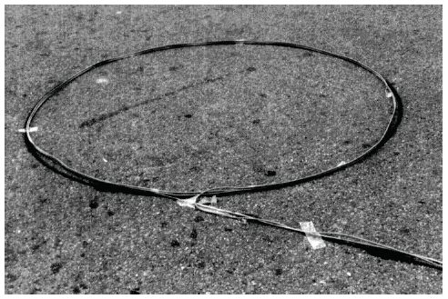
Figure 5-10. Prewound loop installation.p
A preformed inductive loop is an inductive coil that is manufactured before installation in the road surface. Preformed loops are usually encased in a protective jacket or conduit to mechanically and electrically isolate the coil and lead-in wires. Preformed loops are installed using two different methods: paveover and sawcut. Primarily, they are paved over during the construction of new road surfaces. Secondarily, they are installed in sawcut grooves similar to field-wound sawcut loops. Preformed loops are an important alternative to field-wound sawcut loops, which suffer frequent failure as a result of the factors below:
Preformed loops address these problems by mechanically protecting the wires from damage and by fixing the number of turns and perimeter of the loop. Paveover preformed loops avoid the problems associated with sealant because there is no sawcut to compromise road surface integrity. However, the low profile of some sawcut preformed loops means they are less likely to migrate out of the sawcut. Preformed loops have demonstrated improved reliability, stable electrical isolation from ground, and a long physical life.
Preformed loops are available in two different designs: conduit-type preformed loops and the InstaLoop™ sensor. Conduit-type loops are constructed of a continuous length of insulated wire encased in a heavy wall plastic pipe or conduit. The InstaLoop™ is manufactured from heavy-duty multiconductor cable.
Figure 5-11 illustrates a conduit-type preformed loop commercially manufactured by several companies. In addition to the square shape, preformed loops are also available in rectangular and round configurations. Local signal maintenance shops frequently construct these loops from readily available materials for installation in their own municipalities. Homemade preformed loops can easily be customized to suit the requirements of the local agency, and are less expensive than the commercially available preformed loops. Commercial preformed loops come in several conduit sizes and materials suitable for different methods of installation. The outside diameters of the conduits range from a minimum of 3/8 inch (9 mm) to greater than 1 inch (25 mm). Typical conduit materials are common PVC irrigation pipe and fiber-reinforced hydraulic hose. Although the narrowest versions of this style of preformed loop are advertised for installation in a sawcut, a perfectly formed 0.5-inch- (12-mm-) wide sawcut is required to accommodate pipe fittings, causing a concomitant lack of adjustability. Therefore, conduit-type preformed loops are limited to paveover installations.
Figure 5-12 shows the InstaLoop™ sensor, which is made of heavy-duty multiconductor cable instead of wire wound inside conduit. This more efficient design enables the use of narrow, 0.25-inch- (6-mm-) wide sawcuts, which minimize road damage. Also, the lower profile InstaLoop™ paveover sensor reduces reflective road surface cracking. Sensitivity, signal quality, and noise rejection are all improved due to optimal geometry and twisted pair lead-in cable. InstaLoops™ are far more flexible than conduit-type loops, simplifying shipment, storage, transportation, and installation at the job site. Most importantly, they are field- and laboratory-tested to be highly resistant to cuts, scrapes, chemicals, and water damage.
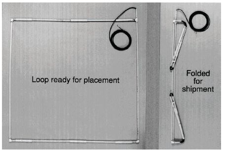
Figure 5-11. Preformed loop assembly.
|
Other manufacturers of preformed paveover inductive loops for asphalt and concrete are Patriot Technologies, International Road Dynamics, Lead-In Systems and Debron Inc. These products have a maximum outside diameter of 5/8 inch (16 mm). |
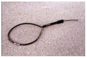 Figure 5-12. InstaLoop™ Paveover Sensor. |
The InstaLoop™ has two unique features that improve performance: installation in a 0.25-inch- (6-mm-) wide sawcut groove and adjustable loop size. Sensor width is minimized and sensitivity maximized through use of multiconductor flat cable that stacks the wires in the slot. A 0.25-inch- (6- mm-) wide linear junction transitions the loop cable into the lead-in cable and thereby allows adjustment of the loop head size through movement of the junction located in the lead-in sawcut. The junction is fully sealed and rated for direct burial.
Preformed Loop Sensor Installation
Preformed loops can be installed in new road surfaces under concrete or asphalt and can be installed in sawcut slots.
Concrete Paveover Installation
To install paveover loop sensors under concrete, the loop must be secured in the desired position while the cement is poured. On bridge decks and roads where reinforcement bar is exposed before the pour, the preformed loops can be tied directly to the bars to hold them in place. Otherwise, they can be laid on the base course in position, and small piles of concrete placed on points along the loop head and lead-in to hold it in place. Once the loops are in place, concrete is poured as usual while making sure not to move the loops after they are covered.
Asphalt Paveover Installation
Installing preformed loops under asphalt is more challenging because of the requirement to ensure that the loops are not damaged or moved during the paving operation. Installation problems may occur due to the following three factors:
A metal-sheathed loop known as mineral-insulated cable was first included in National Electrical Code (NEC) in 1953. It finds use in hazardous locations or difficult environments. Mineral-insulated cable is an assembly of one or more conductors insulated with a highly compressed refractory mineral insulation and enclosed in a liquid-tight seamless metallic sheath with a polyethylene jacket. The mineral insulation is magnesium oxide and the seamless sheath is phosphorus deoxidized copper.
Mineral-insulated installations are found in many industries, including mining, aerospace, marine, petrochemical, and cryogenic, and in blast furnaces. Its application to inductive-loop detector installations is made possible by the observation that loop wires operate efficiently while encased in metal. These installations appear to be best suited to loops installed on the base course, previous to their being covered with the asphalt or concrete surface course. The loop is factory-assembled. The conductors are installed in the tubing parallel to each other, permitting the formation of a loop of the desired number of turns using one cable.
Among the inherent advantages of this type of loop cable is the excellent shielding system.Shielding starts at the electronics unit and continues through the electronics unit wiring harness to the controller cabinet field terminals. The shielding proceeds through the lead-in cable to the corner of the loop and finally terminates at the opposite corner of the loop. To realize the advantage of the shielding, the metal shield must be opened at the far corner of the loop. It is recommended that 1 / 2 to 1 inch (1.27–2.54 cm) of the metal shield be removed and the exposed material and sheath waterproofed at this corner. The lead-in cable shield needs to be connected to both sides of the exposed sheath at the connection corner of the loop in the pull box. All loop and sheath connections must be waterproofed to ensure that the shielding system is insulated from ground except at the electronics unit end.
IDOT developed a regulated procedure for installation of loop wire to combat haphazard construction procedures that seriously degraded performance. IDOT uses mineral-insulated cable loops primarily in new pavements and for replacing loops that are destroyed by widening and resurfacing projects. Figure 5-13 shows the installation detail suggested by the IDOT. Their specification is reproduced in Figure 5-14 for those agencies interested in using this type of product.(7)
Figure 5-13. Metal-sheathed loop cable installation.
One continuous wire must be laid from the pull box through the curb, around the loop the designated number of turns, and back to the pull box. The supply reel should be checked before installation to ensure that there is a sufficient amount of wire on the reel for the particular installation. Careful count must be made of the turns of wire installed in the slot. This is a common error; the workmen simply lose count, particularly when four or more turns are required. Prewound and preformed loops, created in the shop, help ensure the proper number of turns in the loop.
The wire should be laid in the slot so that there are no kinks or curls. A blunt tool such as a paint stirrer may be used to push the wires to the bottom of the slot. Some agencies use a narrow blunt wheel rolled along the slot. A sharp instrument (e.g., a screw driver) should never be used as it easily penetrates the wire insulation.
A special installation problem is encountered when the wire has to cross a pavement joint. When the loop is placed in a concrete roadway and crosses a pavement joint, particularly an expansion joint, the movement of one slab relative to another will cause the wire to break if some special treatment is not used to protect the wire. Additionally, one of the most common failure points is where the road surface meets the curb line. This area is subject to both vertical and horizontal shifting.
There are two basic treatments for crossing the pavement joint. One method is to encase the portion of wire crossing the joint in some type of conduit, as shown in Figure 5-15. Many agencies use rigid plastic conduit or flexible tubing. The State of Illinois has used common rubber garden hose in some of their installations. The material should be approximately 0.75 inch (1.9 cm) in diameter and at least 1 ft (30 cm) long. The conduit is placed in a cut, which measures 1.25 inches (31 mm) wide and 16 inches (40 cm) long, as shown in Figure 5-16.
SPECIFICATION FOR METAL SHEATHED LOOP CABLE The cable shall be #16 AWG with two, three, or four conductors as shown on the plans rated for 300 Volts with outside diameters of 0.306, 0.337, and 0.353 inches, respectively. The cable shall be furnished with a terminal with subassembly kit composed of a pot, cap, sealer, and sleeves. Installation shall consist of furnishing and installing Mineral-Insulated Cable Detector Loop on a bituminous or PCC base course and covering it with bituminous surface course as described and detailed herein and in the plans. To install the cable, slanted holes of 1-inch diameter shall be drilled through the base course. Where curb and gutter are present, the hole shall begin where the base course and gutter meet. Where curbs are not present, the hole shall begin about 1 foot from the edge of the pavement. The cable shall not be installed until the loop area is ready to be covered (by the surface course) to minimize the traffic or asphalt truck running over the cable. The installation of the cable requires the forming of the loop size including the leads to terminal end with some spare, cutting the cable, and immediately sealing the terminal ends to prevent absorption of moisture by the mineral. The leads shall be bound together and inserted through the hole and positioned in place to make splices in the proposed junction box. The cable shall be secured to an asphaltic base course including the leads. The corner radius for the loop shall not be less than 6 inches. The leads shall be bound together with straps or fish tape rope (do not use wire) to prevent cutting or damaging the polyethylene cover. Shovels of asphalt can be used to hold the cable in place. The termination of the cable involves the stripping of the cable ends, installation of fittings, application, or insulating compound and installing the sleeve assembly according to manufacturer's instructions. When the stripping is completed, the exposed mineral-insulated material should be sprayed with an insulating spray. The termination procedure must be completed to avoid leaving the magnesium oxide exposed and the conductor sleeves open that allows moisture to enter them. The sleeved conductors shall be spliced together and tested with a loop test meter to ensure a proper connection. The conductors must be cleaned of the material coating to ensure a good connection while metering. The conductors must be soldered together and each conductor wrapped with two layers of rubber or vinyl electrical tape. The wrapping shall completely cover the soldered connection and the conductor sleeves for 1/2 inch. A loop test meter is used to ensure the loop will perform for detecting vehicles and after obtaining an acceptable reading, the spliced conductors are then sealed by centering them in a bottle mold and filling the mold with epoxy-type resin. The resin must completely cover the tapes on the sleeves. Any exposed copper sheath and the end seal pot shall be taped and coated with a silicone spray to prevent any moisture contact with their surfaces. Any electrical contact between the copper sheaves and the ends of the cables will destroy the inductance reading. No splice shall be permitted in the loop wire beyond the lead-in cable splice or controller terminal when the loop wire is connected directly to the controller terminal. The inductance and resistance of the loop as metered shall be within 10% of the calculated values for that loop as shown on the loop detail sheet.
|
Figure 5-14. IDOT specification and installation procedures for metal-sheathed loop cable.
The alternative installation technique provides an excess of wire at the pavement joint. The most common method for securing additional space for the extra wire is to make the cut in the shape of a diamond. The cut should be small, 2 inches (5 cm) from edge to edge, excavated to the full depth of the sawed slot. This allows sufficient space for an “S” shape of excess wire to be placed in the cut out diamond as shown on Figure 5-17. The diamond (and the adjacent joint, if necessary) is filled with an appropriate sealant.
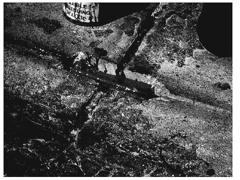
Figure 5-15. Crossing pavement joints using rigid tubing.
Figure 5-16. Pavement joint crossing details.
| 1 inch = 2.5 cm |
Figure 5-17. Crossing pavement joints using diamond cut.
The two lead-in wires from the start and end of the loop turns should be twisted together to form a symmetrically twisted pair from the loop to the pull box. Depending on agency policy, an additional 3 to 5 ft (0.9 to 1.5 m) of lead-in pair slack should be provided in the pull box.
Lead-in wire must be twisted to avoid crosstalk. Agencies vary on the specified number of twists per foot, ranging from two twists per foot to five twists per foot. Manufacturers feel strongly that wires should be twisted a minimum of five to six twists per foot. Some agencies or contractors do not twist the wires because the twisted wires require a wider slot for the lead-in wires, necessitating a larger saw blade than that required for the loop sawcut. Agencies that do not twist the lead-in wires usually allow only one pair of lead-ins per lead-in slot.
The correct and incorrect ways of twisting lead-in wires are illustrated in the top portion of Figure 5-18. Although wires may be twisted by hand, more effective methods, shown at the bottom of the figure, employ (1) an anchor clamp and stick and (2) electrical tape and a mechanical twister to speed up the process.
A multiple-loop configuration is frequently used to emulate a long loop. For this type of loop system, the loops may be wired in series, in parallel, or in series-parallel, as discussed in Chapter 2. The applicable wiring alternative is determined by the inductive-loop system designer through consideration of factors such as system configuration, system requirements, and the recommendations of the selected electronics unit manufacturer. The proper connections for each of the wiring alternatives are shown in Figure 5-19.
Figure 5-18. Method of twisting lead-in wires.
Figure 5-19. Loop wire winding diagrams for multiloop installations.
Typically, the twisted lead-in wire must extend from its lane location in the roadway across the curb or shoulder to the pull box. If a curb is present, passage through the curb is usually accomplished by using a jackhammer drill or punch-type tool to make the entry as shown in Figure 5-20. Liquid-tight flexible conduit is then installed in the hole for insertion of the twisted loop lead-in wire from the sawcut. The conduit should terminate in the pull box above the drainage to prevent moisture from entering the conduit. Figure 5-21 shows a cross-section view of the conduit through which wire from the sawcut enters the pull box. The conduit should be installed at the same time as the pull box.
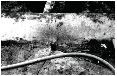
Figure 5-20. Entry hole for curb crossing installations.
Figure 5-21. Loop lead-in wire placement in conduit at roadway-curb interface.
| 1 inch = 2.5 cm |
Where the curb and gutter section is relatively shallow, the lead-in wire is placed in rigid conduit near the edge of the roadway. The conduit is inserted under the curb and gutter as shown in Figure 5-22. The roadway end of the conduit is normally 2 inches (5 cm) below the roadway surface.
In some cases, the crew will simply cut the curb and pass the lead-in wire through the curb. Unless the cut is made to a minimum depth of 18 inches (45 cm) below the surface, this practice is not recommended. When the wires remain too close to the surface, they could be severed by grass trimming or other maintenance activities.
Figure 5-22. Detail of lead-in wire placement for shallow curb section.
Some agencies will drill through pavement before reaching the curb and gutter and will install a conduit beneath the curb section en route to the pull box. These agencies believe this is a simpler installation process than drilling through the concrete curb. Other agencies claim it to be more disruptive to the pavement integrity. It does, however, eliminate problems with the joint between the pavement slab and the curb-gutter section.
When a curb is not present, a hole is drilled through the edge of the pavement to the pull box at a 45-degree angle, as depicted in Figure 5-23. The top of the hole should be at least 6 inches (15 cm) from the edge of the pavement. The hole should be aligned with the pull box and be of sufficient size to accept an appropriately sized conduit.
Figure 5-23. Loop lead-in wires at pavement edge when no curb is present.
| 1 inch = 2.5 cm |
The purpose of the pull box (also referred to as a splice box, handhole, or junction box) is to house the splices between the lead-in wires from the loop and the lead-in cable to the controller cabinet. Additional pull boxes may be required at specified intervals on long runs to the electronics units in the controller housing. Pull boxes can be made of concrete, plastic, metal, or fiberglass.
Figure 5-24 illustrates a standard pull box. Typically, this is a no. 3 or no. 5 pull box in most installations. The box type and location should be specified and shown on the construction plans. Many agencies specify that the pull boxes, conduits, and curb cuts must be completed before beginning the loop wire installation. Typical installation details are shown in Figure 5-25.
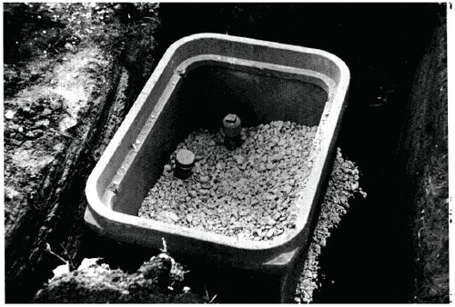
Figure 5-24. Standard pull box.
| 1 inch = 2.5 cm
Figure 5-25. Pull box installation detail. |
The lead-in wires are protected by conduit inserted into the hole through the curb or pavement and connected to the pull box. Although a 3 / 4-inch (1.9-cm) conduit is adequate for a single pair of lead-in wires (one loop), it is common to use a 1-inch (2.5-cm) minimum conduit. Table 5-9 gives the size of conduit as a function of the number of loop conductors. Normally, no more than two twisted pairs are installed in one sawcut slot; however, sometimes loop leadin wires are collected at an in-street pull box (i.e., a pull box located in the travel way) and then routed to the terminal pull box in a conduit under the pavement.
At the roadway end, the conduit should be terminated 2 inches (5 cm) below the pavement surface and a nonmetallic bushing attached to protect the leadin wires. For further protection, the lead-in wires should be taped for several inches on each side of the bushing. Finally, each loop lead-in wire should be tagged for identification with the loop number and the start ("S") and finish ("F") of each individual loop.
| Conduit size inches (cm) | Number of pairs of loop conductors |
|---|---|
1 (2.5) |
1–2 |
1.5 (3.7) |
3–4 |
2 (5) |
5 or more |
Continuity, inductance, and resistance of the loop and lead-in wire should be verified before the loop wires are sealed in the pavement. Tests should be conducted with one or more loop tester devices capable of measuring the induced ac voltage, inductance in microhenrys (µH), integrity of the wire insulation, and loop wire resistance in ohms. A loop insulation tester, such as the one shown on the left in Figure 5-26, measures loop insulation resistance at 500 volts in the range of 5 megohms to 500 megohms and loop wire resistance in the range of 0 to 10 ohms. The frequency tester, shown on the right, measures loop frequency to determine inductance. An inductive-loop system analyzer, such as the model illustrated in Figure 6-2, may also be used to measure these parameters.
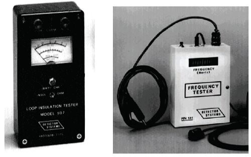
Figure 5-26. Loop test devices.
The integrity of the wire insulation can also be measured with a megohmmeter (popularly called a "megger"). The loop insulation resistance should be in excess of 100 megohms between each end of the lead-in and the nearest reliable electrical ground (e.g., street light or fire hydrant) under any operational condition.
The wiring diagram of the plan set or the inspection report should include a table of calculated values of the inductance in microhenrys and resistance in ohms for each loop. Two values should be shown: one at the pull box without the lead-in cable, and the second at the controller cabinet with the lead-in cable connected. The loop installation is acceptable under the following conditions:
The measured values obtained from the test should be recorded on the wiring plan (or on an inspection report described later under "Final Tests and Record Keeping"). This information is used for future testing and maintenance. Reference 8 describes procedures utilized by Caltrans to verify the operation and measure the sensitivity of a new loop installation. These procedures involve the following steps:
One of the major challenges in inductive-loop detector technology is protecting the loop wires from breakage, moisture, and from floating to the top of the sawcut and becoming vulnerable to the ravages of traffic. The critical factors are sealant selection and application technique. Sealant types, application methods, and wire protection within the slots are discussed below.
Matching the proper sealant with the type and condition of the roadway, together with appropriate, well-supervised installation techniques, are the key factors to effective, maintenance-free inductive-loop detector operation.
During the 1970s, sealant types were about equally divided between asphaltbased and epoxy-based sealants. Early asphalt-based sealants were heated before application. These were soon replaced with gun-grade asphalts marketed as caulking compounds. These, in turn, were superseded by epoxy sealants. The early epoxies were too hard and brittle to adapt well to shifts in pavements and were expensive and difficult to apply.
Available sealants possess a variety of desirable characteristics. Hardness allows the sealant to resist the penetration of foreign materials and street debris such as nails or metal fragments, which might pierce or break the wire. Flexibility allows deformation without cracking during thermal expansion and contraction. Corrosive resistance protects against road salts, gasoline, antifreeze, transmission fluids, brake fluid, and engine oils commonly found on roadway surfaces. Other advantageous sealant properties are good adhesion, and contraction and expansion characteristics similar to those of the highway material in which it is installed.
A rapid curing rate and the ability to be applied to damp surfaces are other beneficial sealant traits. A rapid curing rate is desirable because it minimizes lane-closure time to traffic. During the saw-cutting operation, a water-cooled blade is generally used, and even though the slot may be cleaned with compressed air, some residual dampness may remain. In such cases, it is desirable to apply the sealant directly to damp surfaces rather than first drying them with butane torches, which is time consuming and may damage the asphalt road surface.
Three material families grouped by composition and manufacturing process are recommended for sealing and filling asphalt-surfaced pavements.(1) These are:
A summary of asphalt concrete crack treatment material types, test methods, applications, and cost is given in Table 5-10. Table 5-11 describes the properties of recommended asphalt concrete sealant materials. Sealants recommended for use with portland cement concrete are shown in Table 5-12.(9) A synthesis of the state of the technology in overlays for hot-mix asphalt and portland cement concrete can be found in Reference 10.
| Material | Applicable specification | Recommended application | Cost range based on 1998 costs ($/kg) |
|---|---|---|---|
| Asphalt emulsion | ASTM D 977, ASTM D 2397, AASHTO M 140, AASHTO M 208 | Filling | 0.15 to 0.30 |
| Asphalt cement | ASTM D 3381, AASHTO M 20, AASHTO M 226 | Filling | 0.15 to 0.30 |
| Fiberized asphalt | Manufacturer’s recommended specifications | Filling | 0.35 to 0.60 |
| Polymer-modified emulsion | ASTM D 977, ASTM D 2397, AASHTO M 140, AASHTO M 208 | Filling (possibly sealing) | 0.80 to 1.20 |
| Asphalt rubber | State specifications, ASTM 5078 | Sealing (possibly filling) | 0.45 to 0.65 |
| Rubberized asphalt | ASTM D 1190, AASHTO M 173, Fed SS-S-164 | Sealing | 0.55 to 0.85 |
| ASTM D 3405, AASHTO M 301, Fed SS-S-1401 | Sealing | 0.65 to 1.10 | |
| Low-modulus rubberized asphalt | State-modified ASTM D 3405 specifications | Sealing | 0.75 to 1.40 |
| Self-leveling silicone | ASTM D 5893 | Sealing | 5.75 to 6.75 |
| $1 /kg = $2.17 /lb |
Sealant applications are characterized as either cold-pour or hot-pour types. Cold-pour types include polyester resin, epoxies, polysulfide bases, and rubberized asphalt. The hot-pour varieties include hot pitch, asphalt, and rubberized asphalt. Both cold- and hot-pour sealants must not revert to their liquid state during hot weather as this would allow the loop wire to float to the surface. Sealant should always be fluid enough during application to level itself on a horizontal surface, but should not run when applied on an inclined surface. The sealant must always be applied in strict adherence with the manufacturer’s instructions.
| Property | Material type | |||||||
|---|---|---|---|---|---|---|---|---|
| Emul- Sion | Asphalt cement | Fiberized asphalt | Polymermodified emulsion | Asphalt rubber | Rubberized asphalt | Lowmodulus rubberized asphalt | Selfleveling silicone | |
Short preparation |
||||||||
Quick and easy to place |
||||||||
Short cure time |
||||||||
Adhesiveness |
||||||||
Cohesiveness |
||||||||
Resistance to softening and flow in cured state |
||||||||
Flexibility |
||||||||
Elasticity |
||||||||
Resistance to aging and weathering |
||||||||
Resistance to abrasion |
||||||||
| Material | Applicable specification | Design extension* (%) | Cost range based on 1998 estimated costs ($/L) |
|---|---|---|---|
| PVC coal tar | ASTM D 3406 | 10 to 20 | 1.75 to 2.75 |
| Rubberized asphalt | ASTM D 1190, ASTM D 3405, AASHTO M 173, AASHTO M 301 | 15 to 30 | 0.60 to 1.00 |
| Low-modulus rubberized asphalt |
Modified ASTM D 3405 | 30 to 50 | 0.70 to 1.20 |
| Polysulfide (1 and 2 part) |
Fed SS-S-200E | 10 to 20 | Not available |
| Polyurethane | Fed SS-S-200E | 10 to 20 | 5.20 to 7.20 |
| Silicone (nonsag) |
ASTM D 5893 | 30 to 50 | 6.50 to 9.00 |
| Silicone (self-leveling) |
ASTM D 5893 | 30 to 50 | 6.50 to 9.50 |
| * Consult manufacturers’ specifications for specific design extensions. |
| $1 /G = $3.8 /L |
Hot tar continues to be used because of its low initial cost. Several States, however, have prohibited its use due to the high percentage of failures and the danger and inconvenience to workers during application. The heat involved (sometimes exceeding 500 °F (260 °C)) in the process frequently breaks down or deforms the insulation of the loop wire, diminishing its insulating integrity. In addition, hot tar sealant becomes soft in hot weather and allows vehicles to track the tar from the sawcut. Rocks and other debris can penetrate the soft surface and eventually damage the loop wire insulation.
Rubberized asphalt appears to be the sealant of choice, particularly for asphalt pavements. Its use requires the specified loop wire to have insulation that can withstand the 400 °F (205 °C) application temperature of the rubberized asphalt sealant. Modern epoxy formulations have overcome some of their early drawbacks and are now formulated to provide a greater degree of flexibility.
A number of States have conducted extensive tests of various, commercially available sealants prior to listing the acceptable sealant products in their specifications.(11) In reviewing the documentation of these State tests, a product that scored highest in one State was sometimes considered unacceptable in another State. The disparities in test results are probably caused by differences in geographic and climatic conditions, as well as methods of testing the products. However, most agencies are consistent in product approval criteria. This, in turn, suggests that agencies should periodically validate their tests and test procedures to ensure that their specifications are appropriate.
Common practices for sealing the loop wire are depicted in Figure 5-27. One procedure (shown on the left of Figure 5-27) consists of applying a layer of sealant to the floor of the sawcut after thoroughly cleaning and drying the slot. The loop wires are then laid in the slot and covered with a second, final layer of sealant. This method tends to fix the position of the loop wires in the middle of the sawcut, protecting them on the top and bottom. Some agencies believe that this procedure, although more costly, protects the loop wires from water intrusion.
In the technique illustrated in the middle of Figure 5-27, the wire is simply laid in the slot and covered with sealant. There is no way to control the positioning of the wire in the slot. In a three-wire installation, the three layers of wire may form a triangle on the bottom of the slot or may stack over each other.
The backer rod/sealant combination shown on the right of Figure 5-27 is based on the theory that stresses on sealant during elongation are reduced if the sealant has less depth. With this method, the wires are placed in the slot and then a backer rod (generally a closed-cell polyethylene rope) is forced into the slot over the wires. The remainder of the slot is then filled with sealant. The backer rod assures a shallow layer of sealant, reducing tensile stresses and leaving the wires free to adapt to shifting of the pavement. An alternative method that is becoming increasingly popular is to insert short pieces of the backer rod of approximately 1 inch (2.5 cm) in length every foot or two (30 cm to 61 cm) to anchor the wire in the slot before applying the sealant.
1 inch = 2.5 cm Figure 5-27. Methods of applying sealant. |
Table 5-13 lists commonly used backer rod materials, testing method standards, backer rod properties, and compatibility.
| Material | Applicable standard | Properties* | Compatibility |
|---|---|---|---|
Extruded closed-cell polyethylene |
ASTM D 5249, Type 3 | NMA, ECI, NS | Most cold-applied sealants |
Cross-linked extruded closed-cell polyethylene |
ASTM D 5249, Type 1 | HR, NMA, ECI, NS | Most hot- and cold applied sealants |
Extruded polyolefin |
ASTM D 5249, Type 3 | NMA, NS, NG, CI, IJ | Most cold-applied sealants |
| * CI = chemically inert, ECI = essentially chemically inert, HR = heat resistant, IJ = fills irregular joint well, NG = nongassing, NMA = nonmoisture-absorbing, NS = nonstaining. |
No published evidence of the superiority of one sealant application method over another has appeared. Most inductive-loop detector installers agree that the neat arrangement of wires as shown in many published illustrations is simply not indicative of actual installations; rather, the lay of the wires is random in the slot. They agree that complete encapsulation by the sealant is seldom achievable. Some installers also argue that placing sealant in the bottom of the saw cut (as depicted on the left in Figure 5-27) before laying the wire is time-consuming and requires more road-closure time. Installers indicated that even when this method of installation is specified, it is unlikely to be followed unless an agency inspector was actually overseeing the installation. This is another illustration of the need for careful installation inspection.
On the other hand, proponents of placing sealant on the bottom of the sawcut report that the extra protection afforded by the sealant bed prevents the intrusion of water through small pavement cracks. It also avoids the possibility of sharp edges or rocks becoming dislodged and piercing the installation. Others feel that this is a remote possibility, particularly if the sawcut is well cleaned of debris. Alternatively, some agencies specify the placement of a layer of sand rather than sealant at the bottom of the sawcut. This provides a smooth bed but does not prevent the intrusion of water through pavement cracks.
The amount of sealant to be applied should be sufficient to completely fill the sawcut, but not overfill. A trowel or other tool should be used to ensure that the sealant is slightly below the pavement surface and to remove any excess sealant. Figure 5-28 shows the result of poor installation procedures. It shows overfilling, underfilling, and air bubbles in the sealant. All three conditions can lead to inductive-loop detector failure and should have been corrected during the installation process.
Sealant may be applied with a special applicator as shown earlier in Figure 5-6 or by hand directly from a container as depicted in Figure 5-29. In this illustration, one member of the crew is placing the lead-in wires in the slot while another is pouring the sealant into the sawcut. A paint stirrer has been inserted into the slot to hold the wire down while the sealant is being applied. Other techniques can be used (e.g., backer rod strips, and nylon rope) to hold the wire securely in place while sealant is added. Figure 5-30 shows the crew properly completing the sealant application procedure by removing any excess material from the pavement and dusting talc on the fresh sealant.
A number of agencies and loop installers coat the newly applied sealant with sand or talc after the sealant has been applied and before opening the lane to traffic. This prevents tracking of the sealant during its curing process and allows earlier opening of the traffic lane.
Some sunbelt agencies use sand as the sealant by tamping it into the slot after the wire is placed in the sawcut. However, the sand is easily tracked out of the slot and the wires may become dislodged. Therefore, this practice is not recommended.
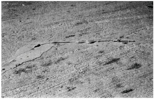
Figure 5-28. Poor sealant application.
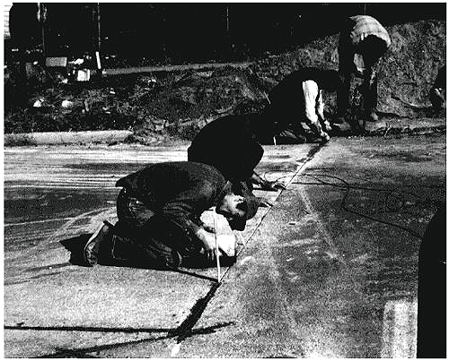
Figure 5-29. Crew applying sealant by hand.
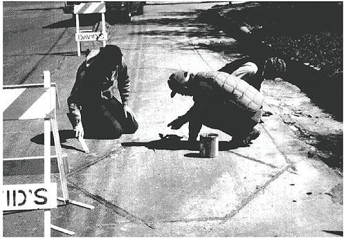
Figure 5-30. Finishing sealant application.
Another critical step in the loop installation process is splicing the loop leadin wire to the lead-in cable that connects to the electronics unit in the controller cabinet. This splice, located in the pull box, should be the only splice in the loop system. The splice is frequently the cause of inductive-loop detector system failure; however, if proper splicing procedures are used, the splice should not pose a problem. There are two steps to creating a splice: the physical connection of the wires and the environmental sealing of the connection.
Methods for physically connecting the lead-in wires from the loop with the lead-in cable vary among agencies. The two preferred methods are twisting and soldering or crimping and soldering. Most electronics unit manufacturers specify a solder connection in their installation procedures. The argument for soldering is that it provides a connection with lower resistance and has less susceptibility to corrosive degradation. The soldered connection will, therefore, require less maintenance in the long run.
While pressure connectors (crimping) without soldering may have been generally acceptable in the past, the use of solid-state electronic assemblies now makes soldered connections preferable. These assemblies operate at low voltage levels and minimum current loads. Because of this, they are susceptible to even slight voltage drops, which occur where poor electrical connections cause high resistance in a circuit.
The procedures for making a twisting and soldering or crimping and soldering connection begin in the same manner as shown in Figure 5-31. First, about 8 in (20 cm) of the outer covering of the lead-in cable is stripped away. One wire is clipped about 3 in (7.5 cm) shorter than the other. About 1.5 inch (4 cm) of the wire insulation must be stripped away from the cable wires and the loop lead-in wires. The appropriate wires are then twisted together (end to end) or crimped with a noninsulated butt connector. Care must be exercised to assure that the correct wires are connected
High-quality crimp connections can be made using a pressure crimping tool that provides a uniform 360-degree crimp. Only bare wire, and not the adjacent insulation, should be inserted into the crimp connector. The individual wire splices should be staggered so that the entire cable spice does not become too bulky. Soldered connections should be made with 60/40 (tin/lead) resin core solder. The Ontario Ministry of Transport specifies the use of 60/40 (lead/zinc) resin core solder as an alternative.(6)
| 1 inch = 2.5 cm |
Figure 5-31. Splicing loop wire at pull box.
Once the wires are firmly spliced, it is essential that the splice be environmentally sealed against weather, moisture, abrasion, etc. A variety of methods are used, including heat-shrinkable tubing, special sealant kits, special forms to be filled by sealant, pill bottles with slot sealant, tape and coating, etc. Any method is acceptable as long as it provides a reliable environmental seal.
When using heat shrinkable tubing, the wires must be inserted in the tubes before they are joined. Two small tubes are used for the individual wires and one large tube to cover the entire splice area. The wires are connected and soldered as described earlier, and the small tubes are centered over the connections and are gradually heated by an electric heat gun or butane torch until the tubes have shrunk uniformly around the wires. The larger tube is now positioned over the splice and heated in the same manner, taking care to avoid burning the wire insulation or the cable jacket. Once the tubes have been shrunk over the splice area including the cable end, a secure environmental seal has been established.
Special sealant kits are commercially available. These kits may have onepart or two-part sealants. One-part sealants are ready to apply. Two-part sealant kits usually contain the resin and hardener in separate compartments of a plastic package. The seal between the two parts is broken and the two components mixed. The package is then cut open and the sealant is formed over the splice area. It is important to ensure that the mixture penetrates between the wires.
An alternative process places a form around the splice area. A liquid sealant is poured into the form; care must be taken to totally fill it with sealant and ensure that no voids appear within the splice area.
A simple encapsulation process consists of using a common drug store pill bottle as shown in Figures 5-32 and 5-33. The wires are spliced side by side rather than end to end. After the wires are twisted and soldered (some agencies add a wire nut or tape the joint), the completed splices are inserted into a pill bottle that has been filled with sealant or electrical epoxy.
Some agencies still use electrical tape to seal the splices. This procedure is not recommended. However, if tape is used, it should be high-quality electrical tape. Each wire connection should be taped separately and then the entire splice area covered by several layers of overlapped tape. A waterproof sealant should then be applied to the entire taped area.
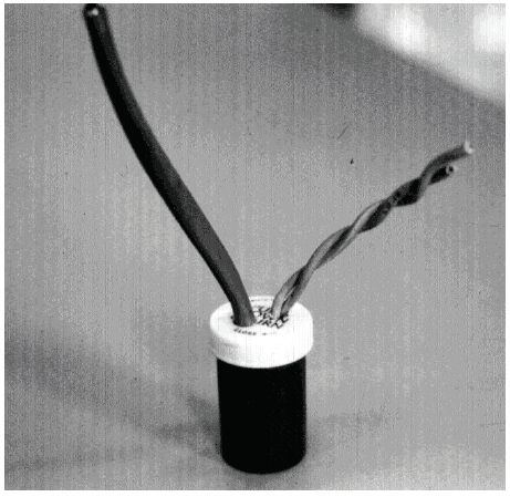
Figure 5-32. Pill bottle splice.
| 1 inch = 2.5 cm |
In general practice, the lead-in cable from the pull box to the controller cabinet is buried bare or placed in conduit below the surface of the ground. In either case, the cable should be buried in a trench at least 18 inches (45 cm) below the surface. If conduit is used, it should be waterproofed.
Trenching is the most common method for installing underground cable. The construction plans should specify the depth of the trench. The trench is backfilled in layers not to exceed 6 inches (15 cm) after the cable is placed in the trench. It is recommended that each layer of backfill be compacted with mechanical tampers to the approximate density of the surrounding ground. No extra material should remain when the backfill procedure is complete.
The lead-in cable terminates inside the controller cabinet at the field terminal strip as illustrated in Figure 5-34. An excess of 18 inches (45 cm) of cable should be provided in the cabinet housing.
Some equipment manufacturers and agencies recommend that the shield of the cable not be connected to the third or ground terminal. One manufacturer describes this technique by stating that the cable shield should be insulated from ground and float at both ends (namely at the cabinet and in the pull box). This recommendation is the same as that from the Ontario Ministry of Transportation, which does not recommend grounding the lead-in cable shield at either end. (See Appendix N, Section IV, bullet 3.) The justification given for this procedure is that the detection system operates at extra-low voltage (e.g., typically, output voltage for an inductive-loop electronics card is 5 V, with a current draw measured in milliamperes) and the cabinet and card rack are firmly connected to ground.
Figure 5-34. Lead-in cable grounding at the field terminal strip.
Other manufacturers recommend grounding at the cabinet (i.e., connecting the shield to the terminal as in Figure 5-34) and insulating the end of the cable in the pull box. This allows any electrical disturbance or interference to be safely grounded without affecting the loop lead-in cable.
NEMA avoids the issue by stating that "Field installation practices or inductive-loop detector electronics unit design may require grounding the shield of the loop lead-in cable. Such grounding should be in accordance with the electronics unit manufacturer’s recommendation."
The loops are capacitively coupled to the earth and receive a voltage surge whenever lightning currents enter the ground nearby and cause an earth voltage rise. These surges may need to be suppressed where the cable enters the controller cabinet or where these circuits enter the electronics units. Back-to-back zener diodes or neon lamps usually provide adequate protection.
Most modern electronics units have built-in lightning protection features. Even so, some agencies in lightning prone areas (specifically Ontario, Canada(6) and Florida) recommend that additional protection be added, such as two neon lamps or two gas-filled surge-voltage protectors connected to the terminal strip, as shown in Figure 5-34. Other grounding and lightning protection approaches are described in Appendixes N and O.
Final tests are recommended after all loops and cables are installed. The final tests repeat the initial tests, described previously in this section, to ensure the inductive-loop detector installation is performing as expected and is fully operational after all cables have been buried.
The test results should be recorded on an installation data sheet such as the one depicted in Figure 5-35. Any modifications made to the original plan drawings should be noted, dated, and retained as "As Built" plans.
The inspector should verify that the correct readings from the tests are recorded and that the modified plans reflect the as-built conditions. These records comprise the history of the particular inductive-loop detector system and serve as the baseline for any future maintenance or repair activity.

Figure 5-35. Representative inductive-loop installation data sheet.
General guidelines for installing inductive-loop detectors at signalized intersections are presented in Table 5-14.(12,13) These general guidelines apply under a wide variety of circumstances. The design engineer is cautioned that installations at specific locations may require that other design, installation procedures, testing, etc., be followed.
Design
|
Installation of Loop Wire and Lead-in Cables
|
Testing
|
Sealant
|
Connections
|
Previous | Table of Contents | Next
FHWA-HRT-06-139 |

