U.S. Department of Transportation
Federal Highway Administration
1200 New Jersey Avenue, SE
Washington, DC 20590
202-366-4000
Federal Highway Administration Research and Technology
Coordinating, Developing, and Delivering Highway Transportation Innovations
 |
| This report is an archived publication and may contain dated technical, contact, and link information |
|
Publication Number: FHWA-HRT-04-091
Date: August 2004 |
||||||||||||||||||||||||||||||||||||||||||||||||||||||||||||||||||||||||||||||||||||||||||||||||||||||||||||||||||||||||||||||||||||||||||||||||||||||||||||||||||||||||||||||||||||||||||||||||||||||||||||||||||||||||||||||||||||||||||||||||||||||||||||||||||||||||||||||||||||||||||||||||||||||||||||||||||||||||||||||||||||||||
Signalized Intersections: Informational GuidePDF Version (10.84 MB)
PDF files can be viewed with the Acrobat® Reader® CHAPTER 3 — GEOMETRIC DESIGNTABLE OF CONTENTS3.2 Number of Intersection Legs 3.4 Horizontal and Vertical Alignment 3.5 Corner Radius and Curb Ramp Design 3.6.3 Intersection Sight Distance
LIST OF FIGURES
LIST OF TABLES 3.0 Geometric DesignThis chapter presents geometric design guidelines for signalized intersections based on a review of technical literature and current design policy in the United States. Geometric design of a signalized intersection involves the functional layout of travel lanes, curb ramps, crosswalks, bike lanes, and transit stops in both the horizontal and vertical dimensions. Geometric design has a profound influence on roadway safety; it shapes road user expectations and defines how to proceed through an intersection where many conflicts exist. In addition to safety, geometric design influences the operational performance for all road users. Minimizing impedances, eliminating the need for lane changes and merge maneuvers, and minimizing the required distance to traverse an intersection all help improve the operational efficiency of an intersection. The needs of all possible road users (see chapter 2) must be considered to achieve optimal safety and operational levels at an intersection. At times, design objectives may conflict between road user groups; the practitioner must carefully examine the needs of each user, identify the tradeoffs associated with each element of geometric design, and make decisions with all road user groups in mind. This chapter addresses the following topics:
3.1 Channelizationa primary goal of intersection design is to limit or reduce the severity of potential road user conflicts. Basic principles of intersection channelization that can be applied to reduce conflicts are described below.(41) 1. Discourage undesirable movements. Designers can utilize corner radii, raised medians, or traffic islands to prevent undesirable or wrong-way movements. Examples include:
2. Define desirable paths for vehicles. The approach alignment to an intersection as well as the intersection itself should present the roadway user with a clear definition of the proper vehicle path. This is especially important at locations with “unusual” geometry or traffic patterns such as highly skewed intersections, multileg intersections, offset-t intersections and intersections with very high turn volumes. Clear definition of vehicle paths can minimize lane changing and avoid “trapping” vehicles in the incorrect lane. Avoiding these undesirable effects can improve both the safety and capacity at an intersection. Figure 11 shows how pavement markings can be applied to delineate travel paths.
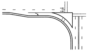
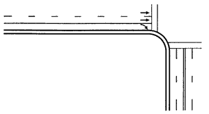
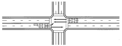
3. Encourage safe speeds through design. An effective intersection design promotes desirable speeds to optimize intersection safety. The appropriate speed will vary based on the use, type, and location of the intersection. On high-speed roadways with no pedestrians, it may be desirable to promote higher speeds for turning vehicles to remove turning vehicles from the through traffic stream as quickly and safely as possible. This can be accomplished with longer, smooth tapers and larger curb radii. On low-speed roadways or in areas with pedestrians, promotion of lower turning speeds is appropriate. This can be accomplished with smaller turning radii, narrower lanes, and/or channelization features. These are illustrated in figure 12.
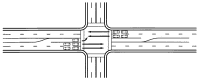
Figure 12. Various right-turn treatments may be used, depending on the speed environment. 4. Separate points of conflict where possible. Separation of conflict points can ease the driving task while improving both the capacity and safety at an intersection. The use of exclusive turn lanes, channelized right turns, and raised medians as part of an access control strategy are all effective ways to separate vehicle conflicts. Figure 13 illustrates how the addition of a left-turn lane can reduce conflicts with through vehicles traveling in the same direction.
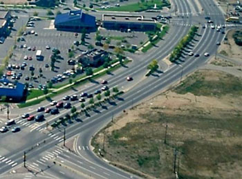
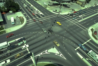
Figure 13. Providing a dedicated left-turn lane reduces potential collisions between left-turning and through vehicles, increasing the capacity of the approach for both left and through traffic. 5. Facilitate the movement of high-priority traffic flows. Accommodating high-priority movements at intersections addresses both driver’s expectations and intersection capacity. The highest volume movements at an intersection typically define the intersection’s high-priority movements, although route designations and functional classification of intersecting roadways may also be considered. In low-density suburban and rural areas, it may be appropriate to give priority to motor vehicle movements; however, in some urban locations, pedestrians and bicyclists at times may be the highest priority users of the road system. Figure 14 shows an intersection where double left and right turn lanes are used to facilitate high-volume turning movements.
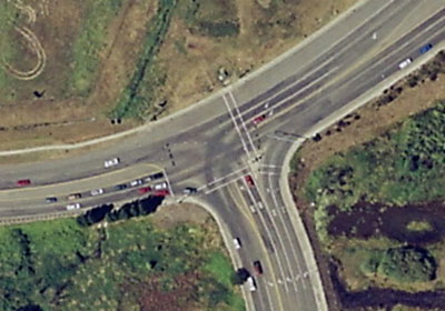
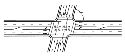
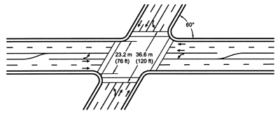
6. Design approaches to intersect at near right angles and merge at flat angles. Roadway alignments that cross as close to 90 degrees as practical can minimize the exposure of vehicles to potential conflicts and reduce the severity of a conflict. Skewed crossings produce awkward sight angles for drivers, which can be especially difficult for older drivers. Skewed crossings also result in additional distance for vehicles to traverse the intersections. This additional distance should be considered when developing the timing for a signal, as it may require the need for additional all-red clearance time. Figure 15 shows how a skewed intersection approach can increase the distance to clear the intersection for pedestrians and vehicles.
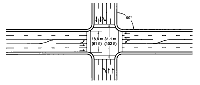
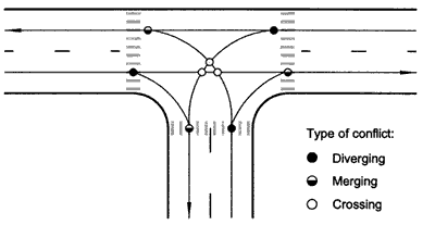
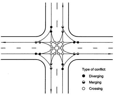
Figure 15. Intersection skew increases both the intersection width and pedestrian crossing distance. 7. Facilitate the desired scheme of traffic control. The design of a signalized intersection should attempt to maximize traffic safety and operations while providing operational flexibility. Lane arrangements, location of channelization islands, and medians should be established to facilitate pedestrian access and the placement of signs, signals, and markings. Consideration of these “downstream” issues as part of design can optimize the operation of an intersection. Providing exclusive left-turn bays that can accommodate left-turn movements can improve operations and safety while providing flexibility to accommodate varying traffic patterns. Positive offset left-turn lanes can improve sight distance for left-turning movements but may prohibit U-turns if insufficient width is available. Reversible lanes may be appropriate for arterials that experience heavy directional peaks in traffic volumes during commuter periods. 8. Accommodate decelerating, slow, or stopped vehicles outside higher speed through traffic lanes. Speed differentials between vehicles in the traffic stream are a primary cause of traffic crashes. Speed differentials at intersections are inherent as vehicles decelerate to facilitate a turning maneuver. The provision of exclusive left- and right-turn lanes can improve safety by removing slower moving turning vehicles from the higher speed through traffic stream and reducing potential rear-end conflicts. In addition, through movements will experience lower delay and fewer queues. 9. Provide safe refuge and wayfinding for bicyclists and pedestrians. Intersection design must consider the needs of roadway users other than motorists. Intersection channelization can provide refuge and/or reduce the exposure distance for pedestrians and bicyclists within an intersection without limiting vehicle movement. The use of raised medians, traffic islands, and other pedestrian-friendly treatments should be considered as part of the design process. Wayfinding may also be an issue, particularly at intersections with complicated configurations. 3.2 Number of Intersection LegsWhile the geometry of various types of intersections may vary, the complexity of an intersection increases with an increasing number of approach legs to the intersections, as shown in figures 16 and 17. The latter shows the number and type of conflicts that occur at intersections with three and four legs, respectively. The number of potential conflicts for all users increases substantially at intersections with more than four legs. Note that many potential conflicts, including crossing and merging conflicts, can be managed (but not eliminated) at a signalized intersection by separating conflicts in time.
Figure 17. Potential conflicts at intersections with three and four legs. 3.3 Intersection angleThe angle of intersection of two roadways can influence both the safety and operational characteristics of an intersection. Heavily skewed intersections not only affect the nature of conflicts, but they produce larger, open pavement areas that can be difficult for drivers to navigate and pedestrians to cross. Such large intersections can also be more costly to build and maintain. Undesirable operational and safety characteristics of skewed intersections include:
Skewed intersections are generally related to right-angle type crashes that can be associated with poor sight distance. AASHTO policy and many State design standards permit skewed intersections of up to 60 degrees.(3) Gattis and Low conducted research to identify constraints on the angle of a left-skewed intersection as it is affected by the vehicle body’s limiting a driver line-of-sight to the right.(43) Their findings suggest that if roadway engineers are to consider the limitations created by vehicle design, a minimum intersection angle of 70 to 75 degrees will offer an improved line of sight. FHWA’s Highway Design Handbook for Older Drivers and Pedestrians recommends intersection angles of 90 degrees for new intersections where right-of-way is not a constraint, and angles of not less than 75 degrees for new facilities or redesigns of existing facilities where right-of-way is restricted.(12) 3.4 Horizontal and Vertical AlignmentThe approach to a signalized intersection should promote awareness of an intersection by providing the required stopping sight distance in advance of the intersection. This area is critical as the approaching driver or bicyclist begins to focus on the tasks associated with navigating the intersection. To meet the driver’s or cyclist’s expectations on approaches to an intersection, the following guidelines are suggested:
3.5 Corner Radius and Curb Ramp DesignIntersection corners that are designed appropriately accommodate all users. The selection of corner radius and curb ramp design should be guided by pedestrian crossing and design vehicle needs at the intersection. In general, it is recommended to provide a pedestrian crossing that is as near to perpendicular to the flow of traffic as practical with no intermediate angle points. This keeps pedestrian crossing time and exposure to a minimum, which may allow more efficient operation of the signal. It also aids visually impaired pedestrians in their wayfinding task by eliminating changes in direction that may not be detectable. Corner radii should also be designed to accommodate the turning path of a design vehicle to avoid encroachment on pedestrian facilities and opposing lanes of travel. 3.5.1 Corner RadiusThe corner radii of an intersection should be designed to facilitate the turning and tracking requirements of the selected design vehicle. Other considerations when designing a corner radius include location of traffic control devices (signal poles, controller, signs, etc.), the need to provide channelizing islands, and available right-of-way. The corner radii should be compatible with other intersection features and the speed environment. For example, larger radii are more compatible with high-speed facilities with few pedestrians, whereas smaller radii are more compatible with low-speed facilities with many pedestrians.(41) Factors that influence the selection of appropriate corner radii include the following:
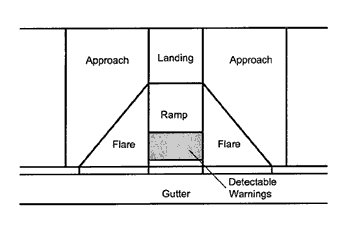
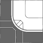
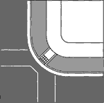
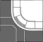
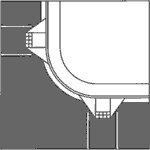
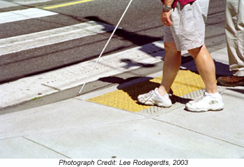
3.5.2 Curb Ramp DesignCurb ramps provide access for people who use wheelchairs and scooters. Curb ramps also aid people with strollers, luggage, bicycles, and other wheeled objects in negotiating the intersection. The basic components of a curb ramp, including ramp, landing, detectable warning, flare, and approach, are diagrammed in figure 18. The ADAAG require that curb ramps be provided wherever an accessible route crosses a curb, which includes all designated crosswalks at new and retrofitted signalized intersections.(33) While curb ramps increase access for mobility-impaired pedestrians, they can decrease access for visually impaired pedestrians by removing the vertical curb face that provides an important tactile cue. This tactile cue is instead provided by a detectable warning surface placed at the bottom of the ramp, which provides information on the boundary between the sidewalk and roadway.
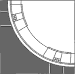
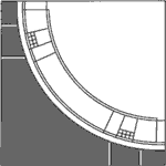
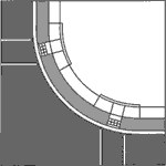
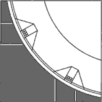
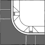
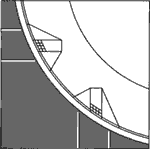
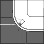
Table 9, adapted from FHWA’s Designing Sidewalks and trails for Access, Part 2: Best Practices Design Guide, provides a summary of recommended fundamental practices for curb ramp design, along with the rationale behind each practice.(34) A designer can apply these principles in designing intersections in a wide variety of circumstances. Figures 19-21 provides examples of three categories of typical curb ramp treatments used at signalized intersections: those that should be implemented wherever possible (“preferred designs”), those that meet minimum accessibility requirements but are not as effective as the preferred treatments (“acceptable designs”), and those that are inaccessible and therefore should not be used in new or retrofit designs (“inaccessible designs”). Additional guidance and design details can be found in the source document.(34) Table 9. Summary of best practices for curb ramp design and associated rationale.
Source: Adapted from reference 34, table 7-1.
Source: Reproduced from reference 34, table 7-2
3.5.3 Detectable WarningsThe ADAAG require that a detectable warning surface be applied to the surface of the curb ramps and within the refuge of any medians and islands (defined in the ADAAG as “hazardous vehicle areas”) to provide tactile cues to individuals with visual impairments.(33) Detectible warnings consist of a surface of truncated domes built in or applied to walking surfaces; the domes provide a distinctive surface detectable by cane or underfoot. This surface alerts visually impaired pedestrians of the presence of the vehicular travel way, and provides physical cues to assist pedestrians in detecting the boundary from sidewalk to street where curb ramps and blended transitions are devoid of other tactile cues typically provided by a curb face. At the face of a curb ramp and within the refuge area of any median island, a detectable warning surface should be applied as shown in figure 22. The detectable warning surface begins at the curb line and extends into the ramp or pedestrian refuge area a distance of 610 mm (24 inches). For a median island, this creates a minimum clear space of 610 mm (24 inches) between the detectable warning surfaces for a minimum median island width of 1.8 m (6 ft) at the pedestrian crossing. This is a deviation from the requirements of the ADAAG (§4.29.5), which requires a surface width of 915 mm (36 inches). However, this deviation is necessary to enable visually impaired pedestrians to distinguish where the refuge begins and ends from the adjacent roadway where the minimum 1.8 m (6 ft) refuge width is provided. Table 10 summarizes ADAAG requirements for detectable warning surfaces.
Table 10. Requirements for detectable warning surfaces.
The Draft Guidelines on accessible Public Rights-of-Way, developed by the U.S. Access board, issued a similar recommendation for use of a 610-mm (24-inch) width for detectable warning surfaces.(44) This is consistent with the existing ADAAG requirements for truncated dome detectable warning surfaces at transit platforms. The draft public right-of-way guidelines are based upon the recommendations of the Public Rights of Way Access advisory Committee as published in the report Building a True Community.(45) For detectable warning surfaces, both the U.S. Access board and FHWA are encouraging the use of the new (recommended) design pattern and application over the original ADAAG requirements.(33) 3.6 Sight DistanceA driver’s ability to see the road ahead and other intersection users is critical to safe and efficient use of all roadway facilities, especially signalized intersections. Stopping sight distance, decision sight distance, and intersection sight distance are particularly important at signalized intersections. 3.6.1 Stopping Sight DistanceStopping sight distance is the distance along a roadway required for a driver to perceive and react to an object in the roadway and to brake to a complete stop before reaching that object. Stopping sight distance should be provided throughout the intersection and on each entering and exiting approach. Table 11 gives recommended stopping sight distances for design, as computed from the equations provided in the AASHTO policy.(3) Table 11. Design values for stopping sight distance.
Stopping sight distance should be measured using an assumed height of driver’s eye of 1,080 mm (3.5 ft) and an assumed height of object of 600 mm (2.0 ft).(3) 3.6.2 Decision Sight DistanceDecision sight distance is “the distance needed for a driver to detect an unexpected or otherwise difficult-to-perceive information source or condition in a roadway environment that may be visually cluttered, recognize the condition or its potential threat, select an appropriate speed and path, and initiate and complete the maneuver safely and efficiently.”(3, p. 115) Decision sight distance at intersections is applicable for situations where vehicles must maneuver into a particular lane in advance of the intersection (e.g., alternative intersection designs using indirect left turns). Decision sight distance varies depending on whether the driver is to come to a complete stop or make some kind of speed, path, or direction change. Decision sight distance also varies depending on the environment—urban, suburban, or rural. Table 12 gives recommended values for decision sight distance, as computed from equations in the AASHTO policy.(3)
3.6.3 Intersection Sight DistanceIntersection sight distance is the distance required for a driver without the right of way to perceive and react to the presence of conflicting vehicles and pedestrians. Intersection sight distance is traditionally measured through the determination of a sight triangle. This triangle is bounded by a length of roadway defining a limit away from the intersection on each of the two conflicting approaches and by a line connecting those two limits. Intersection sight distance should be measured using an assumed height of driver’s eye of 1,080 mm (3.5 ft) and an assumed height of object of 1,080 mm (3.5 ft).(3) The area within the triangle is referred to as the clear zone and should remain free from obstacles. The reader is encouraged to refer to the AASHTO policy, pp. 654-680, for a complete discussion of intersection sight distance requirements.(3) Intersection sight distance at signalized intersections is generally simpler than for stop-controlled intersections. The following criteria should be met:
For signalized intersections where two-way flashing operation is planned (i.e., flashing yellow on the major street and flashing red on the minor street), departure sight triangles for Case B should be provided for the minor-street approaches.(3) 3.7 Pedestrian FacilitiesPedestrian facilities should be provided at all intersections in urban and suburban areas. In general, design of the pedestrian facilities of an intersection with the most challenged users in mind—pedestrians with mobility or visual impairments should be done. The resulting design will serve all pedestrians well. In addition, the ADA requires that new and altered facilities constructed by, on behalf of, or for the use of State and local government entities be designed and constructed to be readily accessible to and usable by individuals with disabilities.(33) Therefore, it is not only good practice to design for all pedestrian types, but it is also a legal requirement. Pedestrians are faced with a number of disincentives to walking, including centers and services located far apart, physical barriers and interruptions along pedestrian routes, a perception that routes are unsafe due to motor vehicle conflicts and crime, and routes that are esthetically unpleasing.(46) Key elements that affect a pedestrian facility that practitioners should incorporate into their design are listed below:(47)
3.8 Bicycle FacilitiesSome intersections have on-street bicycle lanes or off-street bicycle paths entering the intersection. When this occurs, intersection design should accommodate the needs of cyclists in safely navigating such a large and often complicated intersection. Some geometric features that should be considered include:
The interaction between motor vehicles and bicyclists at interchanges with merge and diverge areas is especially complex, and some signalized intersections also have merge and diverge areas due to free right turns or diverted movements (see chapter 10). AASHTO recommends that “[i]f a bike lane or route must traverse an interchange area, these intersection or conflict points should be designed to limit the conflict areas or to eliminate unnecessary uncontrolled ramp connections to urban roadways.”(21, p. 62)
|
||||||||||||||||||||||||||||||||||||||||||||||||||||||||||||||||||||||||||||||||||||||||||||||||||||||||||||||||||||||||||||||||||||||||||||||||||||||||||||||||||||||||||||||||||||||||||||||||||||||||||||||||||||||||||||||||||||||||||||||||||||||||||||||||||||||||||||||||||||||||||||||||||||||||||||||||||||||||||||||||||||||||