Highway Design Handbook for Older Drivers and Pedestrians
RECOMMENDATIONS
I. INTERSECTIONS (AT-GRADE)
Background and Scope of Handbook Recommendations
The single greatest concern in accommodating older road users, both drivers and pedestrians, is the ability of these persons to negotiate intersections safely. The findings of one widely cited analysis of nationwide crash data (Hauer, 1988), illustrated below, reveal an enduring relationship between injuries and fatalities at intersections in the United States as a function of age and road user type (driver or pedestrian).
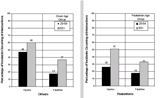
For drivers 80 years of age and older, about half of fatal crashes occur at intersections (48 to 55 percent), compared with 23 percent or less for drivers up to 50 years of age (FARS 1998 data, in IIHS, 2000). Thirty-eight percent of pedestrian deaths among people age 65 and older in 1998 occurred at intersections (IIHS, 2000). These findings reinforce a long-standing recognition that driving situations involving complex speed-distance judgments under time constraints--the typical scenario for intersection operations--are more problematic for older drivers and pedestrians than for their younger counterparts. Other studies within the large body of evidence showing dramatic increases in intersection crash involvements as driver age increases have associated specific crash types and vehicle movements with particular age groups, linked in some cases to the driving task demands for a given maneuver (Campbell, 1993; Council and Zegeer, 1992; Staplin and Lyles, 1991).
Another approach to characterizing older driver problems at intersections was employed by Brainin (1980), who used in-car observations of driving behavior with 17 drivers ages 25-44, 81 drivers ages 60-69, and 18 drivers age 70 and older, on a standardized test route. The two older age groups showed more difficulty making right and left turns at intersections and responding to traffic signals. The left-turn problems resulted from a lack of sufficient caution and poor positioning on the road during the turn. Right-turn difficulties were primarily a result of failing to signal. Older drivers also displayed difficulty during their approach to an intersection. Errors demonstrated at STOP signs included failing to make complete stops, poor vehicle positioning at STOP signs, and jerky and abrupt stops. Errors demonstrated at traffic signals included stops that were either jerky and abrupt, failure to stop when required, and failure to show sufficient caution during the intersection approach.
Complementing crash analyses and observational studies with subjective reports of intersection driving difficulties, a statewide survey of 664 senior drivers by Benekohal, Resende, Shim, Michaels, and Weeks (1992) found that the following activities become more difficult for drivers as they grow older (with proportion of drivers responding in parentheses):
- Reading street signs in town (27 percent).
- Driving across an intersection (21 percent).
- Finding the beginning of a left-turn lane at an intersection (20 percent).
- Making a left turn at an intersection (19 percent).
- Following pavement markings (17 percent).
- Responding to traffic signals (12 percent).
Benekohal et al. (1992) also found that the following highway features become more important to drivers as they age (with proportion of drivers responding in parentheses):
- Lighting at intersections (62 percent).
- Pavement markings at intersections (57 percent).
- Number of left-turn lanes at an intersection (55 percent).
- Width of travel lanes (51 percent).
- Concrete lane guides (raised channelization) for turns at intersections (47 percent).
- Size of traffic signals at intersections (42 percent).
Comparisons of responses from drivers ages 66-68 versus those age 77 and older showed that the older group had more difficulty following pavement markings, finding the beginning of the left-turn lane, and driving across intersections. Similarly, the level of difficulty for reading street signs and making left turns at intersections increased with increasing senior driver age. Turning left at intersections was perceived as a complex driving task. This was made more difficult when raised channelization providing visual cues was absent, and only pavement markings designated which were through lanes versus turning lanes ahead. For the oldest age group, pavement markings at intersections were the most important item, followed by the number of left-turn lanes, concrete guides, and intersection lighting. A study of older road users completed in 1996 provides evidence that the single most challenging aspect of intersection negotiation for this group is performing left turns during the permitted (steady circular green indication) signal phase (Staplin, Harkey, Lococo, and Tarawneh, 1997).
During focus group discussions (Benekohal et al., 1992), older drivers reported that intersections with too many islands are confusing; raised curbs that are unpainted (unmarked) are difficult to see; and textured pavements (rumble strips) are of value as a warning of upcoming raised medians, approaches to (hidden or flashing red) signals, and the roadway edge/shoulder lane boundary. Study subjects indicated a clear preference for turning left on a protected arrow phase, rather than making permitted-phase turns. When turning during a permitted phase of signal operation, they reported waiting for a large gap before making a turn, which frustrates drivers in back of them. A key finding was the need for more time to react.
Additional insight into the problems older drivers experience at intersections was provided by focus group responses from 81 older drivers (Staplin et al., 1997). The most commonly reported problems are listed below:
- Difficulty in turning their heads at skewed (non-90-degree) angles to view intersecting traffic.
- Difficulty in smoothly performing turning movements at tight corners.
- Hitting raised concrete barriers such as channelizing islands in the rain and at night.
- Finding oneself positioned in the wrong lane--especially a "turn only" lane--during an intersection approach, due to poor visibility
(maintenance) of pavement markings or the obstruction Of roadside signs designed to inform drivers of intersection traffic patterns.
- Difficulty at the end of an auxiliary (right) turn lane in seeing potential conflicts well and quickly enough to smoothly merge with adjacent-lane
traffic.
- Merging with adjacent-lane traffic at a pavement width reduction, when the lane drop occurs near (i.e., within 150 m [500 ft]) an intersection.
Finally, the analysis by Council and Zegeer (1992) included an examination of vehicle-pedestrian crashes and the collision types in which older pedestrians were overinvolved. The results showed older pedestrians to be overrepresented in both right- and left-turn crashes. The young-elderly (ages 65-74) were most likely to be struck by a vehicle turning right, whereas the old-elderly (age 75 and older) were more likely to be struck by a left-turning vehicle.
This section will provide recommendations for 17 different design elements in order to accommodate the needs and enhance the performance of road users with age-related diminished capabilities as they approach and negotiate intersections: A. intersecting angle (skew); B. receiving lane (throat) width for turning operations; C. channelization; D. intersection sight-distance requirements; E. offset (single) left-turn lane geometry, signing, and delineation; F. edge treatments/delineation of curbs, medians, and obstacles; G. curb radius; H. traffic control for left-turn movements at signalized intersections; I. traffic control for right-turn/right-turn-on-red (RTOR) movements at signalized intersections; J. street-name signing; K. one-way/wrong-way signing; L. stop- and yield-controlled intersection signing; M. devices for lane assignment on intersection approach; N. traffic signals; O. fixed lighting installations; P. pedestrian crossing design, operations, and control; and Q. roundabouts.
Recommendations by Design Element
| |
A. Design Element: Intersecting Angle (Skew)
|
AASHTO:1
ICG:1
ITE:1
|
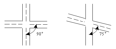
(1) In the design of new facilities or redesign of existing facilities where right-of-way is not restricted, all
intersecting roadways should meet at a 90-degree angle. |
| ITE:2 |
(2) In the design of new facilities or redesign of existing facilities where right-of-way is restricted, intersecting
roadways should meet at an angle of not less than 75 degrees.
 |
ITE:4
MUTCD:3 |
3) At skewed intersections where the approach leg to the left intersects the driver's approach leg at an angle of less than 75 degrees,
the prohibition of right turn on red (RTOR) is recommended [see Recommendation I(3)].
The rationale and supporting evidence for these recommendations
|
| |
C. Design Element: Channelization
|
AASHTO:4
ICG:4
ITE:4
MUTCD:4 |
(1) Raised channelization with sloping curbed medians is recommended over channelization accomplished through
the use of pavement markings (flush), for the following operating conditions:
(1a) Left- and right-turn lane treatments at intersections on all roadways with operating speeds of less than 65 km/h (40 mi/h).
(1b) Right-turn treatments on roadways with operating speeds equal to or greater than 65 km/h (40 mi/h).
|
| MUTCD:4 |
(2) Where raised channelization is implemented at intersections, it is recommended that median and island
curb sides and curb horizontal surfaces be treated with retroreflectorized markings and be maintained at a minimum luminance contrast level* as follows:
(2a) With overhead lighting, a contrast of at least 2.0 is recommended.
(2b) Without overhead lighting, a contrast of at least 3.0 is recommended.
Contrast should be calculated according to this formula:
|
Luminance contrast (C) =
|
Luminancestripe- Luminancepavement
|
Luminancepavement |
* Luminance is the amount of light reflected from a surface to the eye
of a driver. This is different from retroreflectivity, which is a property
of a material. While increasing retroreflectivity generally results in
higher luminance, brightness--especially at night--may vary greatly for
the same target depending upon such factors as the location and intensity
of its source of illumination, and the angle at which a driver views it.
It is the apparent brightness (more accurately,"luminance contrast") of
a target in its surroundings, under representative viewing conditions,
that determines its visibility (detectability) and is the critical predictor
of a safe driver response. Since nighttime visibility of roadway features
is most problematic for older drivers, the contrast calculation for this
design element should be based on nighttime luminance measures; these
should be obtained under low-beam headlight illumination from a passenger
vehicle at a 5-s preview distance upstream of the intersection. Direct
readings of the luminance of a surface can be obtained with a hand-held
light meter that has a through-the-lens viewing system to enable accurate
targeting of the design element. The luminance measurements of the target
and surrounding area may be obtained from any location judged to be in
the line of sight of the driver at the 5-s preview distance.
|
| AASHTO:4 |
(3) If right-turn channelization is present at an intersection, an acceleration lane providing for the acceleration
characteristics of passenger cars as delineated in AASHTO specifications (1994) is recommended. |
| ICG:4 |
(4) The use of sloping curbs rather than barrier curbs for channelization is recommended, except where the
curbs surround a pedestrian refuge area or are being used for access control. |
AASHTO:1
ICG:3
MUTCD:1 |
(5) If right-turn channelization is present and pedestrian traffic may be expected based on surrounding land
use, it is recommended that an adjacent pedestrian refuge island conforming to MUTCD (FHWA, 2000) and AASHTO (1994) specifications be provided.
|
AASHTO:4
ICG:4 |
(6) To reduce unexpected midblock conflicts with opposing vehicles, the use of channelized left-turn lanes in combination with continuous raised-curb
medians is recommended instead of center, two-way, left-turn lanes (TWLTL) for new construction or reconstruction where average daily traffic volumes
exceed 20,000 vehicles per day, or for remediation where there is a demonstrated crash problem, or wherever a need is demonstrated through engineering
study.
The rationale and supporting evidence for these recommendations
|
| |
D. Design Element: Intersection Sight-Distance Requirements
|
| AASHTO:4 |
(1) Where determinations of intersection sight-distance requirements for any intersection maneuver (turn left,
turn right, crossing) that is performed by a driver on either a major or a minor road incorporate a perception-reaction time (PRT) component,
it is recommended that a PRT value of no less than 2.5 s be used to accommodate the slower decision times of older drivers. |
| AASHTO:4 |
(2) Where determinations of intersection sight-distance requirements for a left-turn maneuver from a major roadway by a
stopped passenger car are based on a gap model (see NCHRP Report 383), it is recommended that a gap of no less than 8.0 s, plus 0.5 s for each
additional lane crossed by the turning driver, be used to accommodate the slower decision times of older drivers.
The rationale and supporting evidence for these recommendations
|
| |
E. Design Element: Offset (Single) Left-Turn Lane Geometry, Signing, and Delineation
|
AASHTO:4
ICG:4
ITE:4 |
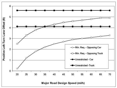
(1) Unrestricted sight distance (achieved through positive offset of opposing left-turn lanes) is recommended whenever possible, for new or
reconstructed facilities. [See figure under Recommendation (3).] This will provide a margin of safety for older drivers who, as a group, do not
position themselves within the intersection before initiating a left turn. |
AASHTO:4
ICG:4
ITE:4 |
(2) At intersections where engineering judgment indicates a high probability of heavy trucks as the opposing turn vehicles during normal operations,
the offsets required to provide unrestricted sight distance for opposing left-turn trucks should be used for new or reconstructed facilities. [See
figure under Recommendation (3).]
|
AASHTO:4
ICG:4
ITE:4 |
(3)
Where the provision of unrestricted sight distance is not feasible, positive left-turn lane offsets are recommended to achieve minimum required sight
distances, which vary according to (major) roadway design speed and type of opposing vehicle (passenger car or heavy truck). For left-turning traffic
that must yield to opposing traffic on a major roadway, the recommended offset values to achieve minimum required sight distances* are as indicated in
the figure below:
1 ft=0.305 m
1 mi/h=1.61 km/h
* The functions graphed above are yielded by computations using either a modified AASHTO Intersection Sight Distance (ISD) formula with
PRT equal to 2.5 s or by gap model calculations with G equal to 8.0 s plus 0.5 s for each additional lane crossed by a turning (passenger car)
driver.
|
| |
(4) At intersections where the left-turn lane treatment results in channelized offset left-turn lanes (e.g.,
a parallel or tapered left-turn lane between two medians), the following countermeasures are recommended to reduce the potential for wrong-way
maneuvers by drivers turning left from a stop-controlled, intersecting minor roadway:
|
ITE:4
MUTCD:4 |
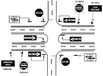
(4a) In the implementation of DIVIDED HIGHWAY CROSSING signs, and WRONG WAY, DO NOT ENTER, KEEP RIGHT, and ONE
WAY signs at the intersection, as per MUTCD (FHWA, 2000) specifications, oversized signs (sizes larger than MUTCD-specified standard
sizes for conventional roadways) are recommended. |
| MUTCD:1 |
(4b) It is recommended that the signs listed in Recommendation (4a) above be fabricated using retroreflective
sheeting that provides for high retroreflectance overall, particularly at the widest available observation angles, to provide increased sign conspicuity
and legibility for older drivers. |
| MUTCD:1 |
(4c) Retroreflective lane-use arrows for channelized left-turn lanes are recommended. |
| MUTCD:3 |
(4d) Retroreflective pavement marking extensions of the center line that scribe a path through the turn are
recommended, except where extensions for opposing movements cross, to reduce the likelihood of wrong-way movements. |
| MUTCD:3 |
(4e) Placement of 7.1-m- (23.5-ft-)
long retroreflective wrong-way arrows in the through lanes is recommended for wrong-way traffic control at locations determined to have a special need,
as specified in the MUTCD (FHWA, 2000), sections 2A.24, 3B.19, and 2E-50. |
AASHTO:1
MUTCD:2 |
(4f) Delineation of median noses using retroreflective treatments to increase their visibility and improve driver understanding of the intersection
design and function is recommended.
The diagram presented below illustrates the countermeasures as described above in Handbook Recommendations E(4a)-(4f).
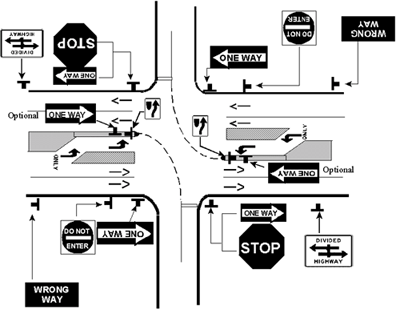
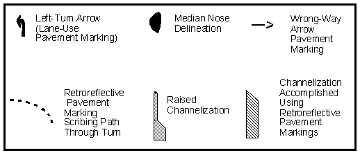
Recommended signing and delineation treatments for intersections with medians 9 m (30 ft) wide or wider.
[Note: Median ONE WAY signs are optional where left-turn lanes result in narrowing of the median, and engineering judgment indicates
a potential for motorist confusion.]
The rationale and supporting evidence for these recommendations
|
| |
F. Design Element: Treatments/Delineation of Edgelines, Curbs, Medians, and Obstacles
|
MUTCD:4
RLH:4 |
(1) It is recommended that a minimum in-service luminance contrast* level between the marked edge of the roadway and the road surface be maintained
as follows:
(1a) At intersections with overhead lighting, a contrast of 2.0 or higher is recommended.
(1b) At intersections without overhead lighting, a contrast of 3.0 or higher is recommended.
Contrast should be calculated according to this formula:
Luminance contrast (C) = |
Luminancestripe - Luminancepavement
|
Luminancepavement |
* See advisory comments pertaining to luminance measurement in Recommendation IC (2).
|
AASHTO:1
MUTCD:2 |
(2) It is recommended that all curbs at intersections (including median islands and other raised channelization) be delineated on their vertical face
and at least a portion of the top surface, in addition to the provision of a marked edgeline on the road surface.
The rationale and supporting evidence for these recommendations |
| |
G. Design Element: Curb Radius
|
AASHTO:1
ICG:1 |
(1)
Where roadways intersect at 90 degrees and are joined with a simple radius curve, a corner curb radius in the range of 7.5 m to 9 m (25 ft to 30 ft)
is recommended as a tradeoff to: (a) facilitate vehicle turning movements, (b) moderate the speed of turning vehicles, and (c) avoid unnecessary
lengthening of pedestrian crossing distances, except where precluded by high volumes of heavy vehicles. |
AASHTO:4
ICG:4
ITE:4 |
(2) When it is necessary to accommodate turning movements by heavy vehicles, the use of offsets, tapers, and compound curves is recommended to minimize
pedestrian crossing distances.
The rationale and supporting evidence for these recommendations
|
| |
H. Design Element: Traffic Control for
Left-Turn Movements at Signalized Intersections
|
ICG:4
ITE:4
MUTCD:4 |
(1) The use of protected-only operations
is recommended, except when, based on engineering judgment, an unacceptable
reduction in capacity will result. |
ITE:4
MUTCD:4 |
(2) To reduce confusion during an
intersection approach, the use of a separate signal face to control turning
phase (versus through) movements is recommended for all operating modes. |
ITE:4
MUTCD:4 |
(3) Consistent use of the R10-12 sign, LEFT TURN YIELD ON GREEN •,
during protected-permitted operations is recommended, with overhead placement
preferred at the intersection.
|
AASHTO:3
MUTCD:4 |
(4) Where practical, the use of a
redundant upstream R10-12 sign (i.e., in addition to the R10-12 sign adjacent
to the signal face) is recommended to advise left-turning drivers of permitted
signal operation. It is also recommended that the sign be displayed at a
3-s preview distance before the intersection, or at the beginning of the
left-turn lane, as per engineering judgment, accompanied by a supplemental
plaque bearing the message, AT SIGNAL. [See time-speed-distance table on
page 3.] |
ITE:2
MUTCD:2 |
(5) A leading protected left-turn
phase is recommended wherever protected left-turn signal operation is implemented
(as opposed to a lagging protected left-turn phase). |
| MUTCD:4 |
(6) To eliminate confusion about
the meaning of the red arrow indication, it is recommended that the steady
green arrow for protected-only left-turn operations terminate to a yellow
arrow, then a steady circular red indication (instead of a red arrow). |
AASHTO:4
ITE:1
MUTCD:1 |
(7) Where minimum sight-distance
requirements as per recommendations for Design Element D are not practical
to achieve through geometric redesign/reconstruction, or where a pattern
of permitted left-turn crashes occurs, it is recommended that permitted
left turns be eliminated and protected-only left-turn operations be implemented.
The rationale and supporting evidence for these recommendations
|
| |
I. Design Element: Traffic
Control for Right-Turn/RTOR Movements at Signalized Intersections
|
ITE:4
MUTCD:4 |
(1)
It is recommended that a steady circular red indication be used at signalized
intersections where a right turn on red is prohibited, instead of a red
arrow indication. |
ITE:4
IEC: requires FHWA permission |
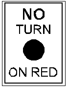 (2)
It is recommended that at signalized intersections where a right turn on red is prohibited, a supplemental NO TURN ON RED sign, using the design shown at right, be placed on the overhead mast arm and at a location on either the near or opposite side of the intersection where, per engineering judgment, it will be most conspicuous. (2)
It is recommended that at signalized intersections where a right turn on red is prohibited, a supplemental NO TURN ON RED sign, using the design shown at right, be placed on the overhead mast arm and at a location on either the near or opposite side of the intersection where, per engineering judgment, it will be most conspicuous. |
ITE:4
MUTCD:3 |
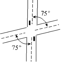
(3)At skewed
intersections where the approach leg to the left intersects the driver's
approach leg at an angle of less than 75 degrees (as indicated below),
the prohibition of right turn on red (RTOR) is recommended.
|
| MUTCD:4 |
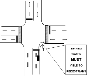
(4) The posting of (black on white)
signs with the legend TURNING TRAFFIC MUST YIELD TO PEDESTRIANS is recommended
wherever engineering judgment indicates a clear potential for right-turning
vehicles to come into conflict with pedestrians who are using the crosswalk
for permitted crossing movements [shown in IP (5)].
The rationale and supporting evidence for recommendations
|
| |
J. Design Element: Street-Name Signing
|
| MUTCD:4 |
(1)
To accommodate the reduction in visual acuity associated with increasing
age, a minimum letter height of 150 mm (6 in) is recommended for use on
post-mounted street-name signs (MUTCD sign number D3) on all roads
where the posted speed limit exceeds 40 km/h (25 mi/h).
|
| MUTCD:4 |
(2)
The use of overhead-mounted street-name signs with mixed-case letters is
recommended at major intersections as a supplement to post-mounted street-name
signs. Minimum letter heights of 200-mm (8-in) uppercase letters and 150-mm
(6-in) lowercase letters are recommended at major intersections with approach
speeds of 56 km/h (35 mi/h) or less. At major intersections with approach
speeds greater than 56 km/h (35 mi/h), the minimum letter height on street-name
signs should be 250-mm (10-in) uppercase and 200-mm (8-in) lowercase letters. |
| MUTCD:2 |
(3) In the design of overhead-mounted
street-name signs, the use of larger letter heights will require a larger
sign panel if the Standard Alphabets for Highway Signs are used. To minimize
sign panel size, while accommodating the larger letter size, it is recommended
that the border be eliminated on street-name signs when using Standard
Alphabets.
|
| MUTCD:4 |
 (4)
Wherever an advance intersection warning sign is erected (e.g., W2-1, W2-2,
W2-3, W2-4), it is recommended that it be accompanied by an advance street-name
plaque (W16-8), as shown, using 200-mm (8-in) black letters on a yellow
sign panel. (4)
Wherever an advance intersection warning sign is erected (e.g., W2-1, W2-2,
W2-3, W2-4), it is recommended that it be accompanied by an advance street-name
plaque (W16-8), as shown, using 200-mm (8-in) black letters on a yellow
sign panel. |
| MUTCD:1 |
(5)
The use of redundant street-name signing for major intersections is recommended,
with an advance street-name sign placed upstream of the intersection at
a midblock location. |
| MUTCD:4 |
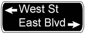
(6) When different street
names are used for different directions of travel on a crossroad, the
names should be separated and accompanied by directional arrows on both
midblock and intersection street-name signs, as shown below:

Or, a two-line sign format may be used to address support and wind load issues:
|
| MUTCD:1 |
(7) For post-mounted street-name
signs installed at intersections in areas of intensive land use, complex
design features, and heavy traffic, it is recommended that retroreflective
sheeting that provides for high retroreflectance overall, and particularly
at the widest available observation angles, be used to provide increased
sign conspicuity and legibility for older drivers.
The rationale and supporting evidence for these recommendations
|
| |
K. Design Element: One-Way/Wrong-Way Signing
|
| MUTCD:1 |
(1)It is recommended that divided highways be consistently signed
as shown in the configuration diagrammed below; use of the DIVIDED HIGHWAY
CROSSING sign (R6-3) is the recommended practice, pending new treatments that are demonstrated through research to provide improved comprehensibility to
motorists. |
| MUTCD:1 |
(2)For divided
highways with median widths less than 9 m (30 ft), the use of four ONE
WAY signs is recommended, located in the left median and far-right corner
of the intersection, as shown in the configuration diagrammed below.
Recommended signing configuration for medians less than 9 m (30 ft).
|
| MUTCD:3 |
(3)For medians ranging from 9- to 13-m (30- to 42-ft) wide, or where
offset left-turn lanes are used with any median width, the use of six ONE WAY signs is recommended, as diagrammed in Recommendation (4) of Design Element
E (see page 18). |
| MUTCD:4 |
(4) For T-intersections, the use
of a near-right- side ONE WAY sign and a far-side ONE WAY sign is recommended;
the preferred placement for the far-side sign is opposite the extended
centerline of the approach leg as shown in MUTCD figure 2A-6
(FHWA, 2000). Where the preferred far-side location is not feasible (e.g.,
because of blockage, distracting far-side land use, or an excessively
wide approach leg), engineering judgment should be applied to select the
most conspicuous alternate location for a driver who has not yet initiated
the wrong-way turning maneuver (see diagram below).
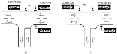
|
| MUTCD:4 |
(5) For the
intersection of a one-way street with a two-way street, ONE WAY signs placed
at the near-right/far-left locations are recommended, regardless of whether
there is left-to-right or right-to-left traffic (see diagram below).
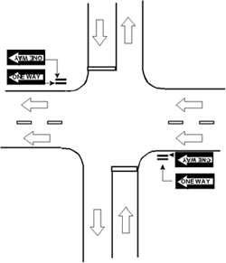
|
AASHTO:4
MUTCD:4 |
(6) As a general practice, the use
of DO NOT ENTER and WRONG WAY signs is recommended at locations where
the median width is 9 m (30 ft) and greater. Consideration should also
be given to the use of these signs for median widths narrower than 9 m
(30 ft), where engineering judgment indicates a special need.
The rationale and supporting evidence for these recommendations
|
| |
L. Design Element: Stop- and Yield-Controlled Intersection Signing
|
| |
Recommendations to improve the safe use of intersections by older drivers, where the need for stop
control or yield control has already been determined, include the following:
|
| MUTCD:1 |
(1)
The use of standard size (750-mm [30-in]) STOP (R1-1) and standard size
(900-mm [36-in]) YIELD (R1-2) signs, as a minimum, is recommended
wherever these devices are implemented, with the option of using larger
R1-1 (900-mm [36-in] or 1200-mm [48-in]) signs where engineering judgment
indicates that greater emphasis or visibility is required. |
ITE:4
MUTCD:4 |
(2) A minimum sign background (red area) retroreflectivity level (i.e., coefficient of retroreflection
[RA]) below which a need for sign replacement is indicated,
is recommended for STOP (R1-1) and YIELD (R1-2) signs as follows:
(2a) 12 cd/lux/m2 for roads with operating speeds lower than 65 km/h (40 mi/h).
(2b) 24 cd/lux/m for roads with operating speeds of 65 km/h (40 mi/h) or higher.
|
| MUTCD:4 |
 (3) The use of a 750-mm x 450-mm (30-in x 18-in) supplemental warning sign panel
(W4-4p), as illustrated, mounted below the STOP (R1-1) sign, is recommended
for two-way stop-controlled intersection sites selected on the basis of
crash experience; where the sight triangle is restricted; and wherever a
conversion from four-way stop to two-way stop operations is implemented.
 |
AASHTO:4
ITE:4
MUTCD:4 |
(4)
It is recommended that a STOP AHEAD sign (W3-1a) be used where the distance
at which the STOP sign is visible is less than the AASHTO stopping sight
distance (SSD) at the operating speed, plus an added preview distance of
at least 2.5 s. [See time-speed-distance table on page 3.] |
| ITE:4 |
(5)
The use of transverse pavement striping or rumble strips upstream of stop-controlled
intersections where engineering judgment indicates a special need due to
sight restrictions, high approach speeds, or a history of ran-stop-sign
crashes is recommended.
The rationale and supporting evidence for this recommendation
|
| |
M. Design Element: Devices for Lane Assignment on Intersection Approach
|
| MUTCD:1 |
(1) The consistent overhead placement of lane-use control signs (e.g., R3-5,
R3-6, R3-8) at intersections on a signal mast arm or span wire is recommended.
|
| MUTCD:4 |
(2) The consistent posting of lane-use
control signs plus application of lane-use arrow pavement markings at
a preview distance of at least 5 s (at operating speed) in advance of
a signalized intersection is recommended, regardless of the specific lighting,
channelization, or delineation treatments implemented at the intersection.
[See time-speed-distance table on page 3.] Signs should be mounted overhead
wherever practical.
The rationale and supporting evidence for these recommendations
|
| |
N. Design Element: Traffic Signals
|
| MUTCD:4 |
(1)
A maintained performance level of 200 cd for peak intensity of
a 200-mm (8-in) red signal is recommended to ensure detectability and improve
conspicuity of this critical control element. |
| MUTCD:2 |
(2) To accommodate age differences
in perception-reaction time, it is recommended that an all-red clearance
interval be consistently implemented, with length determined according
to the Institute of Transportation Engineers (1992) expressions given
below:
(2a) Where pedestrian traffic is prohibited, or no pedestrian crossing facilities are provided, use:
(2b) Where pedestrian crossing facilities are provided, use:
where:
r = length of red clearance interval, to the nearest 0.1 s.
W= width of intersection (m [ft]), measured from the near-side stop line to the far edge of the conflicting traffic lane along
the actual vehicle path.
P= width of intersection (m [ft]), measured from the near-side stop line to the far side of the farthest conflicting pedestrian
crosswalk along the actual vehicle path.
L= length of vehicle ( recommended as 6 m [20 ft]).
V= speed of the vehicle through the intersection (m/s [ft/s]).
|
| MUTCD:4 |
(3) The consistent use of a backplate
with traffic signals on all roads with operating speeds of 65 km/h (40
mi/h) or higher is recommended. The use of a backplate with signals on
roads with operating speeds lower than 65 km/h (40 mi/h) is also recommended
where engineering judgment indicates a need due to the potential for sun
glare problems, site history, or other variables.
The rationale and supporting evidence for these recommendations
|
| |
O. Design Element: Fixed Lighting Installations
|
AASHTO:4
MUTCD:4
RLH:4 |
(1)
Wherever feasible, fixed lighting installations are recommended as follows:
(1a) Where the potential for wrong-way movements is indicated through crash experience or engineering judgment.
(1b) Where twilight or nighttime pedestrian volumes are high.
(1c) Where shifting lane alignment, turn-only lane assignment, or a pavement-width transition forces a path-following adjustment at
or near the intersection.
|
| RLH:4 |
(2)Regular cleaning
of lamp lenses, and lamp replacement when output has degraded by 20 percent
or more of peak performance (based on hours of service and manufacturer's
specifications), are recommended for all fixed lighting installations
at intersections.
The rationale and supporting evidence for these recommendations
|
| |
P. Design Element: Pedestrian Crossing Design, Operations, and Control
|
AASHTO:2
ICG:2
MUTCD:2 |
(1)To accommodate the shorter stride and slower gait of less capable
(15th percentile) older pedestrians, and their exaggerated "start-up" time
before leaving the curb, pedestrian control-signal timing based on an assumed
walking speed of 0.85 m/s (2.8 ft/s) is recommended. |
AASHTO:4
ICG:4
ITE:4
MUTCD:4 |
(2) For pedestrian crossings where the right-turn lane is channelized, it is recommended that:
(2a)An adjacent pedestrian refuge island conforming to MUTCD (FHWA, 2000) and AASHTO (1994) specifications be provided.
(2b)If a crosswalk is within the channelized area, it should be located as close as possible to the approach leg to maximize the
visibility of pedestrians before drivers are focused on scanning for gaps in traffic on the intersecting roadway.
|
IEC: requires
FHWA permission |
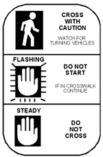
(3)
It is recommended that a placard explaining pedestrian control signal operations and presenting a warning to watch for turning vehicles be posted at the
near corner of all intersections with a pedestrian crosswalk, using the design shown. |
IEC: requires
FHWA permission |
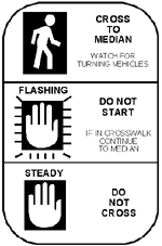
(4)It is recommended that at intersections where pedestrians cross
in two stages using a median refuge island, the placard depicted in Recommendation
P(3) be placed on the median refuge island, and that a placard modified as shown be placed on the near corner of the crosswalk.
|
| MUTCD:4 |
The posting of (black on white) signs with the legend TURNING TRAFFIC
MUST YIELD TO PEDESTRIANS is recommended wherever engineering judgment
indicates a clear potential for right-turning vehicles to come into conflict
with pedestrians who are using the crosswalk for permitted crossing movements
(shown below).
|
| MUTCD:4 |
(6) At intersections with high
pedestrian volumes, high turning-vehicle volumes, and no turn on red (NTOR)
control for traffic moving parallel to a marked crosswalk, a leading pedestrian
interval (LPI), timed to allow slower walkers to cross at least one moving
lane of traffic is recommended to reduce conflicts between pedestrians and
turning vehicles. The length of the LPI, which should be at least 3 s, may
be calculated using the formula:
LPI = (ML + PL)/2.8
where:
LPI = seconds between onset of the WALK signal for pedestrians and the green indicator for vehicles.
ML = width of moving lane in ft.
PL = width of parking lane (if any) in ft.
2.8* = walking speed in ft/s.
* 2.8 ft/s = 0.85 m/
The rationale and supporting evidence for these recommendations
|
| |
Q. Design Element: Roundabouts
|
| |
Recommendations
for preferred practices when a State or local highway authority has determined
through engineering study to install a modern roundabout during construction
or reconstruction of an intersection include the following (see the figure
on the following page that depicts basic geometric elements, from Roundabouts:
An Informational Guide): |
| RND:1 |
(1)Whenever
practical, it is recommended that roundabout installations be limited to
one-lane entrances and exits, and one lane of circulating traffic, with
the inscribed circle diameter limited to approximately 30 m (100 ft). |
| RND:1 |
(2) It is recommended that pedestrian crossings at single-lane roundabouts be set back a minimum of 7.5 m [25 ft] behind the yield line. |
| RND:1 |
(3)To
control for wrong-way movements, calm traffic, and provide a pedestrian
refuge for all roundabout categories, it is recommended that raised splitter
islands be used, as opposed to pavement markings, to delineate the channelization.
The pedestrian crosswalk area should be designed at street level (crosswalk
cut through splitter island). |
| RND:4 |
(4)To enhance the conspicuity of roundabouts in all categories, it
is recommended that the sides and tops of curbs on the splitter islands
and the central island be treated with retroreflective markings, and be
maintained at a minimum luminance contrast level* as follows:
(4a) At roundabouts with overhead lighting, a contrast of 2.0 or higher is recommended.
(4b) At roundabouts without overhead lighting, a contrast of 3.0 or higher is recommended.
Contrast should be calculated according to this formula:
Luminance contrast (C) = |
Luminancestripe- Luminancepavement
|
Luminancepavement |
* See advisory comments pertaining to luminance measurement in Recommendation IC (2).
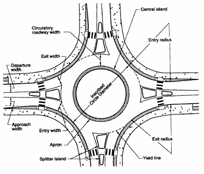
Basic geometric elements of a roundabout.
Source: Roundabouts: An Informational Guide (FHWA, 2000)
The rationale and supporting evidence for these recommendations
|
FHWA-RD-01-103
|

