

| << Previous | Contents | Next >> |
Connection Details for PBES
Appendix A: Connection Design Examples
| Example | Title |
|---|---|
| 1 | Full Depth Precast Concrete Deck Slabs |
| 2 | Precast Column Connections: Column to Cap Connection using mild reinforcement embedded in grouted post-tensioning duct |
| 3 | Precast Column Connections: Precast Column Connections using Grouted Reinforcing Splice Couplers |
Example 1
Full Depth Precast Concrete Deck Slabs
The design of full depth precast concrete deck slabs is similar to the design of a cast-inplace concrete deck with a few exceptions. The AASHTO LRFD Bridge Design Specifications [1] contain provisions for precast full depth deck slabs. Portions of those provisions will be covered in this example.
This example will be for a full depth precast concrete deck slab placed on girders that run parallel to the span. The connections that will be highlighted include the transverse connection between adjacent deck panels and the connection between the slab and the beam. There will also be discussion regarding the design of the actual deck.
Design of Main Reinforcing in the Deck
The design of the main deck reinforcing can be based on the standard design provisions for cast-in-place concrete decks as outlined in the AASHTO LRFD Bridge Design Specifications [1]. The one exception to this is that the empirical design method as specified in Article 9.7.2 is not applicable to precast decks.
The reinforcing in the deck can be mild reinforcing, prestressing (pretensioned or posttensioned), or a combinations of each. The AASHTO specifications cover the design of all of these approaches; therefore a detailed design example is not presented here.
The design of the overhang requires special attention. The maximum moment in the overhang deck can be at the base of the bridge parapet or railing post. This location is often very close to the end of the deck slab. It may not be possible to design this connection using prestressing strand since the moment is normally applied within the development length of the strand and sometimes within the transfer length of the strand. In this case, the overhang slab will need to be supplemented with mild reinforcement.
Design of the connection to the steel beams
The design of this connection is critical to the performance of the superstructure if the design of the girders is based on composite action. Standard shear connectors can be used that are placed in pockets that are cast in the precast deck slab. The pocket shape is normally rectangular with either square or rounded corners. The sides of the pockets can be vertical; however it is recommended that the pockets be tapered from top to bottom for several reasons. It is easier to remove a tapered pocket form in the deck after casting, and a tapered pocket will develop a mechanical connection to the beam.
The design of the shear connectors is according to the AASHTO specifications. Instead of varying the spacing of the connectors across the beam, the spacing is kept constant and the number of connectors in each pocket is varied as the shear demand changes.
Design of the connection to concrete beams
The design of this connection is similar to the steel beam connection above. The AASHTO provisions for horizontal shear design can be followed. If projecting reinforcing is used, the bars need to be spaced in cadence with the proposed slab pocket spacing. Research has shown that embedded headed studs can also be used for this connection [22]. Other research has shown that this connection can be made using embedded steel plates cast into the precast beams [33]. These plates are attached to the beam using shear studs. In the field, the deck is connected in a similar manner as a steel beam.
Transverse Connection with Post-tensioning (PT)
The AASHTO LRFD Bridge Design Specifications [1] contain several provisions that cover the design of post-tensioning systems. This example will cover the sections that are applicable to the design of a post-tensioning for the connection between full depth precast concrete deck slabs.
Givens:
- 200 foot long single span bridge
- Deck information
- 8 inches thick
- 50 feet wide
- f'c = 4000 psi
- PT duct information
- Use 1"x3" Oval polyethylene duct placed flat (inside dimensions)
- Use a maximum of 4-0.5" diameter grade 270 strand for PT
- fpu = 270 ksi
- fpy = 0.9 * fpu = 243 ksi
- Article 9.7.5.3 Longitudinally Post-Tensioned Precast Decks
- The average effective prestress shall not be less than 0.25 ksi.
- This will be the basis of this design example. The prestress is placed at mid-depth of the slab to provide uniform precompression across a grouted shear key joint.
- Article 9.7.5.3 specifies a minimum average effective prestress of 0.250 ksi. Most designers assume this prestress is taken at release and do not account for long term losses due to creep, shrinkage and elastic shortening of the strand. The interaction of the composite prestressed deck with the supporting framing is a very complex situation. Some prestress will be lost due to these effects; however the beam framing will resist these losses. There is not a recognized method for calculating these losses in a composite deck. Most designers assume that 0.250 ksi prestress is conservative enough to cover any minor loss of prestress. For this example, it will be assumed that the effective prestress is taken at release. Losses will be calculated for friction between the duct and the PT strand, anchorage set, and elastic shortening.
- The average effective prestress shall not be less than 0.25 ksi.
- Article 5.4.6.2 Size of Ducts
- For multiple strand tendons: Required Area ≥ 2.5 * As
As = Net area of prestressing steel = 4 * 0.153 = 0.612 in2
Duct Area = 2.79 in2 (from manufacturer)Therefore: 2.79 in2 ≥ 0.612 in2 ok
- Inside diameter ≥ d + 0.25 in.
d = strand diameter = 0.5 in.
Therefore: 1" ≥ 0.5 + 0.25 = 0.75 ok
- Duct size ≤ 0.4 * least gross concrete thickness
Therefore: 1" ≤ 0.4 * 8" = 3.2" ok
- For multiple strand tendons: Required Area ≥ 2.5 * As
- Article 5.9.3 Stress limitations for prestressing tendons
Prior to seating = 0.9fpy = 219 ksi
At anchorages immediately after anchor set = 0.7fpu = 189 ksi - Article 5.9.5.1 Total Loss of Prestress
- For post-tensioned members:
ΔfpT = ΔfpF + fpA + fpES + fpLT
- ΔfpT = total loss (ksi)
- ΔfpF = Loss due to friction (ksi)
- fpA = Loss due to anchorage set (ksi)
- fpES = sum of all losses due to elastic shortening (ksi)
- fpLT = losses due to long-term shrinkage and creep of concrete and relaxation of the steel (ksi)
- Loss due to anchorage set
Elongation = Δ = PL/AEp
In terms of stress = δ = fpA = P/A = ΔEp/LΔ = anchorage set dimension = 0.375 (C5.9.5.2.1)
L = 200 feet = 2400 inches
Ep = Modulus of elasticity of strand = 28500 ksi (5.4.4.2)fpA = 0.375 * 28500 / 2400 = 4.45 ksi
- Loss Due to friction
ΔfpF = fpj (1-e-(Kx + μα))
- fpj = stress in prestressing steel at jacking (ksi)
- Controlling stress after anchor set = 189 ksi (see above)
- Anchorage set stress = fpA = 4.5 ksi (see above)
Therefore: fpj = fpj + fpA = 189 + 4.5 = 193.5
- x = length of prestressing tendon from jacking end to any point under consideration (ft)
- Assume that jacking will be done from one end; therefore the point under consideration will be the far end of the slab
Therefore: x = 200 ft
- Assume that jacking will be done from one end; therefore the point under consideration will be the far end of the slab
- K = wobble coefficient (per foot of tendon)
= 0.0002 (Table 5.9.5.2.2b-1) - μ = coefficient of friction
= 0.23 (Table 5.9.5.2.2b-1) - α = sum of angular change of prestressing steel path
= 0 (straight bridge) - e = base of Napierian logarithms = 2.718
Therefore: ΔfpF = 193.5 (1-e-(0.0002*200 + 0.23*0)) = 7.59 ksi
- fpj = stress in prestressing steel at jacking (ksi)
- Article 5.9.5.2.3 Elastic shortening
There are two portions of this section. One for pretensioned members and one for post-tensioned members. The equations are as follows:Pretensioned members
ΔfpES = (Ep /Ect)* fcgp
Post-tensioned members
ΔfpES = ((N-1)/2N) * (Ep /Ect)* fcgp
The equations are very similar. The PT equation has an additional multiplier term (N-1)/2N. This term will always be less than 1. The notes also state that this value can be multiplied by 0.25 for slab systems. A precast deck system is more similar to a pretensioned beam since the prestressing is concentric and uniform. For this reason, it is recommended that the equation for pretensioned members be used. This is significantly more conservative than equation for PT members.
ΔfpES = (Ep /Ect)* fcgp
Ep = modulus of elasticity of prestressing steel (ksi)
= 28500 ksi (5.4.4.2)Ect = modulus of elasticity of concrete at transfer (ksi)
= 33,000K1wc1.5√fc' (5.4.2.4-1)K1 = correction factor for aggregate
= 1.0 (5.4.2.4)wc = unit weight of concrete (kcf)
= 0.145 (Table 3.5.1-1)fc' = 4.0 ksi (given)
Therefore Ect = 3644 ksi
fcgp = the concrete stress at release (ksi)
= 0.250 ksi (9.7.5.3)Therefore ΔfpES = 1.96 ksi
Therefore the total losses = ΔfpT = ΔfpF + ΔfpA + ΔfpES + ΔfpLT
= 7.59 + 4.45 + 1.96 + 0
= 14.0 ksi
- For post-tensioned members:
- Required number of Post-tensioning Ducts
- Area of bridge deck
Width = 50 feet = 600 in. (given)
Thickness of deck = 8 in. (given)Therefore deck area = 4800 in2
- Required Prestress force
Effective Prestress = fcgp = 0.250 ksi (see Step 1 above)
Therefore the required prestress force = 0.250 * 4800 = 1200 kips
- Number of PT strand required
Prestress after anchorage set = 189 ksi (see Step 3 above)
Anchorage set = 4.45 ksiTherefore stress prior to anchorage set = 189 + 4.45 = 193.45 ksi
Prestress after losses = Effective prestress
= 193.45 - 14.0 = 179.45 ksiArea of strand req. = Asreq
= Req. Prestress force / Prestress after losses
= 1200 / 179.45
= 6.69 in2Area of strand per duct = 0.612 in2
Number of Ducts required = 6.69 / 0.612 = 10.9Therefore use 11 Ducts with 4 - ½ in. diameter grade 270 strand
- Area of bridge deck
Example 2
Precast Column Connections
Column to Cap Connection using mild reinforcement embedded in grouted post-tensioning duct
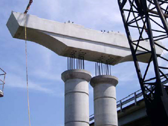
Post-tensioning ducts embedded in precast concrete components offer a means to connect two concrete elements. There are proprietary connectors that are available for this connection (see next section). There is one proprietary option that can be used for several types of connections.
This connection was developed through research undertaken by the Texas Department of Transportation and put into practice on the Lake Belton Bridge (see photo below).
Figure EX2-1 Lake Belton Bridge Pier
Design of the connection and connected components
The design of this connection is currently not covered in the AASHTO LRFD Bridge Design Specifications [1]. The Texas Research project included the development of a design methodology for this connection. The research report for this work is as follows:
Development of a Precast Bent Cap System [49]
Authors: E.E. Matsumoto, M.C. Waggoner, M.E. Kreger, S.L. Wood and J.E. Breen
The University of Texas at Austin, Center for Transportation Research
Published: January 2001
Design Methodology: Pages 251-309
This methodology is well developed and is quite lengthy. In order to keep the size of this manual reasonable, it was decided to not include this detailed design methodology in this appendix. The full research document and design methodology is available at the following website:
http://www.utexas.edu/research/ctr/pdf_reports/0_1748_2.pdf
Seismic Issues
At this time, this connection does not meet the requirements for high seismic applications. Future research may lead to a similar connection that can be used in high seismic areas.
Example 3 Precast Column Connections
Precast Column Connections using Grouted Reinforcing Splice Couplers
Several states have designed and built bridges using grouted reinforcing splice couplers. These couplers are mechanical couplers that take the place of a reinforcing lap splice. There is no requirement for the design of the coupler. They are an off-theshelf item that is normally handled through a performance specification. They are particularly suited for prefabrication because the connector is embedded in the precast concrete component. The connection is made by injecting grout into the cast steel connector.
Figure EX3-1 Grouted Reinforcing Splice Coupler
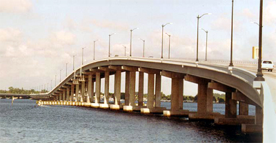
These couplers have been in the building market for many years; however, they are relatively new to the bridge market. One of the first agencies to use these couplers on a bridge project was the Florida Department of Transportation. The Edison Bridge was built using couplers for the column to footing connection and the column to cap connection. The detail above and the photo below are from the Edison Bridge Project.
Figure EX3-2 Edison Bridge
Design of the Grouted Splice Coupler
The AASHTO LRFD Bridge Design Specifications require that all mechanical reinforcing splices develop 125% of the specified yield strength of the bar (Article 5.11.5.2.2) [1]. Several manufacturers make grouted splice couplers that can meet and exceed this requirement.
Design of the Connecting Components
The design of the components is the same as the design of a standard reinforced concrete component with one minor change. The couplers are larger than the connecting bars; therefore in order to obtain proper cover over the coupler, the reinforcing cage needs to be moved toward the interior of the component. This may have an effect on the design of the component since the effective structural depth of the member is reduced when compared to cast-in-place concrete construction. The resulting change will be larger or more closely spaced bars.
Seismic Issues
At this time, this connection has been approved for use on seismic connection designed for Seismic Zones 1 and 2. There is concern that this connection will meet the stringent demands of ductile plastic hinging. Research has been completed in Japan in the past that investigated plastic hinging capabilities of these connections [7]. The following two plots show the results of this limited research. The upper plot is a plot of a control sample column connection built without couplers. The lower plot is a plot of a column connection built with couplers.
Figure EX3-3 Grouted Reinforcing Splice Coupler Test Results
A review of these two plots indicate that the column with the couplers behave essentially the same as the control column and the plastic deformations are well above what is normally required for ductile column behavior. There is concern that this research was not broad enough for acceptance in the US bridge market. Future research may be undertaken to confirm the behavior of these couplers on bridge.
| << Previous | Contents | Next >> |