Falling Weight Deflectometer Calibration Center and Operational Improvements: Redevelopment of The
Calibration Protocol and Equipment
APPENDIX F. HARDWARE USE AND INSTALLATION GUIDE
OVERVIEW/SCOPE
The purpose of this guide is to describe the installation and proper use of the following components of the FWD calibration system (see figure 103):
- Calibration facilities.
- Concrete test pad.
- Reference load cell.
- Concrete anchors.
- Ball-joint anchor.
- Accelerometer box.
- Geophone calibration stand.
- Seismometer calibration stand.
- Geophone adapters.
- Data acquisition components (Keithley DAQ and Vishay signal conditioner).
- Portable computer.
The instructions provided here assume the use of the WinFWDCal software package.
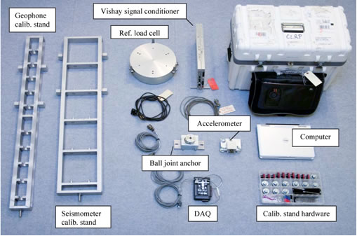
Figure 103. Photo. Calibration system components.
FACILITIES
Calibration center facilities require the following characteristics:
- Easy access for the FWD trailer and the tow vehicle.
- A large level floor that can accommodate both the FWD trailer and the tow
vehicle indoors.
- A stable indoor temperature between 50 and 100 °F (10 and 38 °C).
- Good security cabinets for calibration equipment.
TEST PAD
While a specially built test area for FWD calibration is not required by AASHTO R32-09, some agencies either need or prefer to build a concrete test pad.(1) If so, the test pad should have the following specifications:
- A 12- by 15-ft (4- by 4.5-m) height and an 8-ft (2.5-m)-wide (5-ft (1.75-m) minimum allowable) clear zone around the perimeter to allow for maneuvering of FWD and the calibration equipment.
- A level, smooth, crack-free Portland cement concrete surface. A modest amount of hairline cracking is permissible. Should the test pad develop cracks that are visibly open 0.0585 inches (1.5 mm) or more, it should be replaced.
- It should be isolated from the surrounding floor by impregnated felt bond breaker or sawed and caulked joint.
- It should be at a distance of 20 to 24 inches (500 to 600 mm) behind the FWD load
plate, the test pad should deflect 20 ±4 mil (500 ±100 μm) at a peak dynamic load of 16,000 lbf (71 kN).
REFERENCE LOAD CELL
Parts and Tools
Table 41. Parts and tools for load cell calibration.
| Tool/Equipment |
Quantity |
Notes |
| Reference load cell assembly |
1 |
Drawing CLRP-LC01 |
| ¼ 28 x 1-inch socket head cap screw |
6 |
McMaster-Carr® part number (p/n) 92196A325 |
| ¼ 28 x ¾-inch socket head cap screw |
6 |
McMaster-Carr® p/n 92196A321 |
| Vishay signal conditioner |
1 |
|
| Load cell signal cable |
1 |
Drawing CLRP-DAQ02 |
| 3⁄16-inch hex wrench |
1 |
|
| Torque wrench |
1 |
Capable of 100 inch-lbf |
1 inch = 25.4 mm
1 lbf = 4.45 N
|
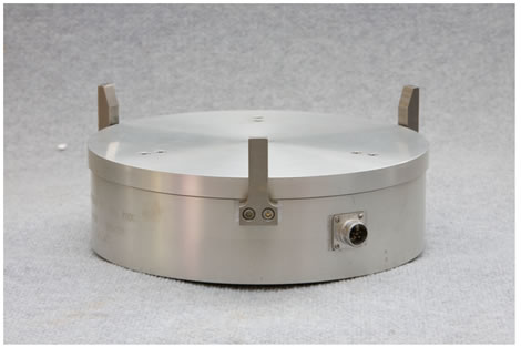
Figure 104. Photo. Reference load cell assembly.
Calibration
The reference load cell requires annual calibration to ensure accuracy. To calibrate the reference load cell, a universal testing machine with a load capacity of 120,000 lbf (500 kN) or more is needed. Although the load cell is calibrated to only 24,000 lbf (107 kN), the higher capacity of the testing machine assures that the test frame will be adequately rigid.
The Vishay 2310 signal conditioner, Keithley KUSB-3108 DAQ, the reference load cell, and the load cell signal cable are considered one system and must be calibrated together. Once the calibration is complete, it only applies to the entire system that was used during the calibration.
If any component of the system changes, then the load cell needs a new calibration.
The bolts that hold the cover plate and feet onto the load cell (see figure 105) should not be removed under any circumstances. If any of these bolts are removed, the load cell calibration becomes invalid and must be returned to an approved calibration center for recalibration.
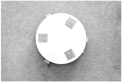
Figure 105. Photo. Bottom view of the reference load cell.
Use
- Ensure that the guide fingers are tightened to the load cell body during FWD load
cell calibration.
- Attach the signal cable form the load cell to the signal conditioner and allow the electronics to warm up for at least 1 h.
- Carefully align the reference load cell under the FWD load plate, ensuring that the guide fingers and the load plate do not interact (see figure 106).
- Follow the on-screen instructions provided by WinFWDCal for a complete load
cell calibration.
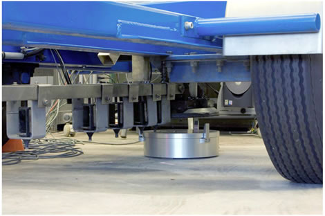
Figure 106. Photo. Reference load cell positioned under the FWD load plate.
CONCRETE ANCHOR INSTALLATION
The concrete anchors suggested for use with the FWD calibration hardware are of the
drop-in variety (see figure 107). These instructions are for anchors from McMaster-Carr®
p/n 97082A031 only. For any other equivalent anchor, refer to the manufacturer’s
installation instructions.
Parts and Tools
Table 42. Parts and equipment for concrete anchor install.
| Tool/Equipment |
Quantity |
Notes |
| Concrete anchors |
2 |
McMaster-Carr®, p/n 97082A031 |
| Anchor setting tool |
1 |
McMaster-Carr® p/n 97077A120 |
| Hammer |
1 |
|
| Drill |
1 |
Optionally a hammer drill |
| ¼-inch masonry drill bit |
1 |
|
| ½-inch masonry drill bit |
1 |
|
| 3⁄8-inch inside diameter washers |
2 |
McMaster-Carr® p/n 94744A273 |
1 inch = 25.4 mm |
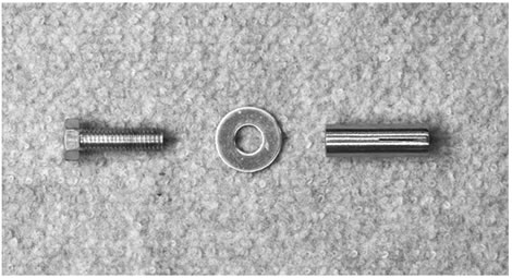
Figure 107. Photo. Concrete anchor.
Installation
- Determine the appropriate location for the ball-joint anchor on the test pad. The FWD needs to impart a deflection of 16–24 mil (400–600 μm) at a 16,000-lbf (71-kN) load where the ball-joint will be located.
- Using the base bar from the ball-joint anchor (B04, drawing CLRP-BJ03) as a guide, mark where the two anchors will be installed. The holes should be 6 inches (152.4 mm) apart from center to center.
- Drill pilot holes at the anchor locations using a ¼-inch (6.35-mm) masonry bit and, if available, a hammer drill. The holes should be slightly greater than 1.5 inches (38.1 mm) deep to ensure that the anchor rests below the surface of the concrete. Ideally, the holes will be drilled about 1⁄16 inches (1.59 mm) deeper than the height of the anchor (see figure 108).
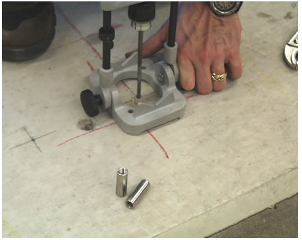
Figure 108. Photo. Concrete anchor installation step 3.
- Drill the final holes for the anchors with a ½-inch (12.7-mm) bit. Do not use a hammer drill for these holes.
- Blow out the debris from holes with compressed air.
- Drop the anchors into the holes and gently tap on the top of the anchor with a hammer to insert it into the hole. Be careful not to damage the anchor. If the anchor does not sit flush in the hole, do not attempt to drive it in by striking the anchor itself directly because this will damage the anchor. If necessary, remove the anchor and drill a little deeper (see figure 109).
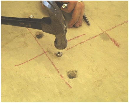
Figure 109. Photo. Concrete anchor installation step 6.
- Once the anchors are at the correct depth in the hole, use the setting tool to expand the anchor by placing the setting tool inside the anchor and striking it with a hammer (see figure 110).
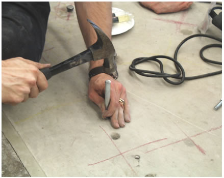
Figure 110. Photo. Concrete anchor installation step 7.
BALL-JOINT ANCHOR
Parts and Tools
Table 43. Tools and equipment for ball-joint assembly.
| No. |
Part/Equipment |
Quantity |
Notes |
| B01 |
Ball-joint |
1 |
Techno/Sommer KG-60 |
| B01a |
Ball |
1 |
Techno/Sommer KG-60 |
| B01b |
Socket |
1 |
Techno/Sommer KG-60 |
| B01c |
Clamp |
1 |
Techno/Sommer KG-60 |
| B01d |
Screw |
2 |
Techno/Sommer KG-60 |
| B02 |
Clamp |
1 |
Drawing CLRP-BJ01 |
| B03 |
Clamp base |
1 |
Drawing CLRP-BJ02 |
| B04 |
Base bar |
1 |
Drawing CLRP-BJ03 |
| B05 |
Rest stop |
1 |
Drawing CLRP-BJ04 |
| B06 |
M6 x 16-mm socket head cap screw |
4 |
McMaster-Carr®
p/n 91292A135 |
| B07 |
M8 x 16 mm socket head cap screw |
6 |
McMaster-Carr®
p/n 91292A145 |
| B08 |
M8 x 25 mm socket head cap screw |
2 |
McMaster-Carr®
p/n 91292A148 |
| B09 |
Loctite® #242 threadlocker |
1 |
|
| B10 |
5-mm hex wrench |
1 |
|
| B11 |
6-mm hex wrench |
1 |
|
| B12 |
Dow Corning Molykote G-4500 alum thickened grease, 14.1-oz, Nlgi #2 |
|
McMaster-Carr®
p/n 4328T24 |
1 inch = 25.4 mm
1 oz = 28.35 g |
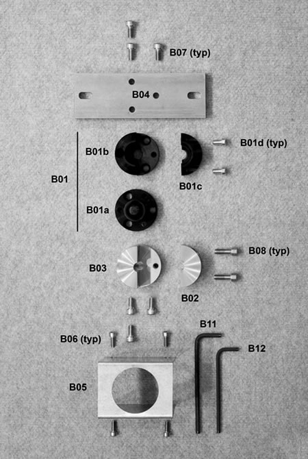
Figure 111. Photo. Parts and tools for ball-joint assembly
Assembly
- Attach the clamp (B02) to the clamp base (B03) with two M8 x 0.975-inch (25-mm) socket head cap screws (B08).
Note: Do not apply Loctite® to the two screws.
Note: Do not apply Loctite® to the two screws.
- Completely disassemble the ball-joint (B01) by removing its two screws (B01d). Thoroughly clean all old lubricant off the ball and socket and apply a thin layer of Molykote® type G lubricant (B12) on the mating surfaces.
- Use Loctite® and three M8 x 0.624-inch (16-mm) socket head cap screws (B07) and mate
the ball-joint’s ball (B01a) and the clamp components assembled in step 1 through the counterbored holes in the ball.
- Reassemble the ball-joint (B01).
Note: Do not apply Loctite® when installing the screws (B01d).
- Attach the base bar (B04) to the completed ball-joint assembly with Loctite® (B09) and three M8 x 0.624-inch (16-mm) socket head cap screws (B07) through the counterbored holes in the bottom of the base bar. The ball-joint screws (B01d) must be aligned along the length of the base bar for access as shown in figure 112.
- Slide the rest stop (B05) over the ball-joint assembly and secure it to the base bar (B04)
with four M6 x 0.624-inch (16-mm) socket head cap screws (B06). See figure 113 for a photograph of the assembly of the ball joint anchor.
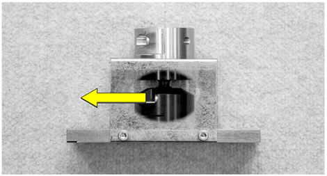
Figure 112. Photo. Proper alignment of ball-joint screws.
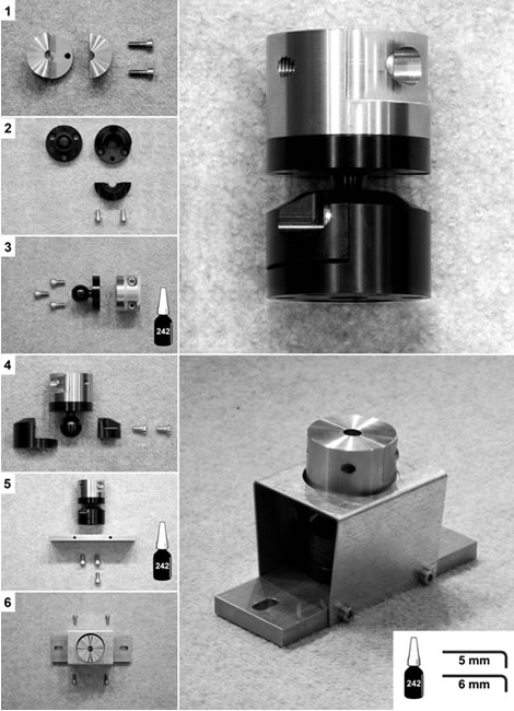
Figure 113. Photo. Assembly of the ball-joint anchor.
ACCELEROMETER BOX
Parts and Tools
Table 44. Parts and tools for accelerometer box assembly.
| No. |
Part/Equipment |
Quantity |
Notes |
| A01a |
Accelerometer assembly |
1 |
|
| A01a |
Accelerometer |
1 |
Silicon Designs model 2220-005 |
| A01b |
Amphenol PT02A-10-6P box mounting receptacle |
1 |
Mouser p/n 654-PT02A106P |
| A01c |
Accelerometer wiring |
1 |
Drawing CLRP-AB05 |
| A02 |
Box bottom |
1 |
Drawing CLRP-AB02 |
| A03 |
Box top |
1 |
Drawing CLRP-AB03 |
| A04 |
Calibration platter |
1 |
Drawing CLRP-AB04 |
| A05 |
#4-40 x 3⁄8-inch flat head Phillips machine screw |
4 |
McMaster-Carr® p/n 96877A209 |
| A06 |
#4-40 x ½-inch pan head Phillips machine screw |
2 |
McMaster-Carr® p/n 91400A110 |
| A07 |
#4 retaining washer |
2 |
McMaster-Carr® p/n 91755A205 |
| A08 |
#4-40 x ¼-inch fillister head Phillips machine screw |
7 |
McMaster-Carr® p/n 91737A072 |
| A09 |
#10-24 x ½-inch knurled head thumbscrew |
2 |
McMaster-Carr® p/n 91746A876 |
| A10 |
Bubble level, glass surface mount |
1 |
McMaster-Carr® p/n 2198A85 |
| A11 |
Leveling mount with polyethylene base, 3⁄8-inch
16 x 1-inch stud |
3 |
McMaster-Carr® p/n 23015T64 |
| A12 |
3⁄8-inch 16 locking wig nut |
3 |
McMaster-Carr® p/n 98520A145 |
| A13 |
#1 Phillips head screwdriver |
1 |
|
| A14 |
Loctite® #242 threadlocker |
1 |
|
1 inch = 25.4 mm
Note: Blank cells indicate that no notes are available. |
Assembly
- The accelerometer is attached to the box top (A03) using two #4-40 x ½-inch (12.7-mm) pan
head machine screws (A06) with #4 nylon retaining washers (A07). The sensor element of
the accelerometer must be oriented in the correct alignment. The element is marked on the
casing of the accelerometer as shown in figure 114. This element must be centered on and
mated to the inside face of the box top.
- Coil the accelerometer wiring (A01c) into the box top and slide the wire through the channel
in the front of the box top so that Amphenol receptacle (A01b) sits flush against the front of
the box.
- The Amphenol receptacle (A01b) is attached to the face of the box top with four
#4-40 x ½-inch (6.35-mm) fillister head machine screws (A08) and medium strength
Loctite® #242 (A14).
- The box top and box bottom (A02) are mated together with four #4-40 x 3⁄8-inch (9.52-mm)
flat head machine screws (A05) and medium strength Loctite® #242 (A14). The final
assembly is shown in figure 115.
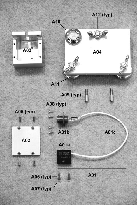
Figure 114. Photo. Parts for accelerometer box assembly.
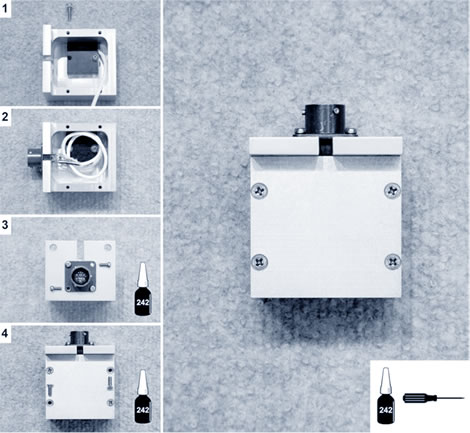
Figure 115. Photo. Accelerometer box assembly.
Calibration Platter Assembly
- Attach the bubble level (A10) to the calibration platter (A04) with three #4-40 x ¼-inch
(6.35-mm) fillister head machine screws (A08). Note that the threaded holes for the
thumbscrews are not centered on the side of the calibration platter. Check for proper
alignment of the accelerometer box on the platter before mounting the bubble level..
- The three leveling mounts are threaded into the calibration platter and topped with three
3⁄8-inch (9.52-mm) 16 locking wing nuts (A12).
- The accelerometer box is attached to the calibration platter with two #10-24 x½-inch
(12.7-mm) knurled head thumbscrews (A09) as shown on the left in figure 116.
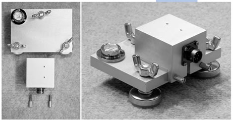
Figure 116. Photo. Accelerometer box attached to calibration platter.
Accelerometer Storage
- When not in use, attach the accelerometer box to the calibration platter with the two #10-24
knurled head thumbscrews (A09) provided.
- The accelerometer needs to be stored on the platter and be level for a minimum of 24 h prior
to use.
Accelerometer Calibration
- Place the calibration platter, with the accelerometer box attached, on a flat surface and
carefully level the platter.
- Remove the thumbscrews and press the accelerometer box on to the calibration platter with a
finger. Otherwise, the weight of the cable may pull the accelerometer box onto the floor.
- While following the on screen instructions from WinFWDCal, continue to press the
accelerometer box to the calibration platter.
- Flip the accelerometer box over when instructed.
CALIBRATION STANDS
Parts and Tools
Table 45. Equipment for calibration stand assembly.
| Number |
Tool/Equipment |
Quantity |
Notes |
| S01 |
Geophone calibration stand assembly |
1 |
Drawing CLRP-GCS01 |
| S02 |
Seismometer calibration stand
assembly |
1 |
Drawing CLRP-SCS01 |
| S03 |
Phenolic handle, 3⁄8-inch
16 x ½-inch stud |
4 |
McMaster-Carr® p/n
62385K65 |
| S04 |
Bubble level, glass surface mount |
2 |
McMaster-Carr® p/n 2198A85;
Also No. A10 in this guide. |
| S05 |
#4-40 x ¼-inch fillister head Phillips machine screw |
6 |
McMaster-Carr® p/n
91737A072; Also No. A08 in this guide. |
| S06 |
Carl Bro geophone adapters with
M8 1 mm threaded through hole |
10 |
Morton Machine Works p/n
KK-GA02 |
| S07 |
JILS geophone adapter with 3⁄8-inch
24 threaded through hole |
0 |
Morton Machine Works p/n
KK-GA03 |
| S08 |
¾-inch inside diameter washer |
10 |
McMaster-Carr® p/n
90126A036 |
| S09 |
3⁄8-inch inside diameter washer |
10 |
McMaster-Carr® p/n
94744A273
Also No. B11 in this guide. |
| S10 |
3⁄8-inch -24 x 5⁄8-inch hex head cap
screw |
10 |
McMaster-Carr® p/n
92865A212 |
| S11 |
#10-24 x ½-inch knurled head thumbscrew |
2 |
McMaster-Carr® p/n
91746A876; Also No. A09 in this manual |
| S12 |
Two-piece clamp-on shaft collar
20-mm bore, 40-mm outside diameter |
10 |
McMaster-Carr® p/n 6063K19 |
| S13 |
Magnet assembly with #10-24 button head cap screw and nut |
10 |
McMaster-Carr® p/n 5685K26,
p/n 92949A246, and p/n
90730A011 |
| S14 |
Modified knurled rim knob |
10 |
McMaster-Carr® p/n 6121K93 |
1 inch = 25.4 mm |
Assembly
See figure 117 for a photograph of the equipment necessary for calibration stand assembly.
- The bubble level (S04) is fastened to the handle holder of either stand (S01 or S02) with three #4-40 x ¼-inch (6.35-mm) fillister head machine screws (S05). Since there are four potential places to attach the level, the calibration center operator should determine which location is appropriate for visibility and comfort during use.
- Two phenolic handles (S03) are screwed in place at one of the two available positions depending on the preference of the operator.
- The pushbutton assembly (described elsewhere) should be attached with Velcro® to the stand at the same level as the handles and in a spot where it can be easily reached during use. See figure 118 for an example.
- For both the geophone calibration stand and the seismometer calibration stand, the connector pin is fastened to the stand with medium strength Loctite® #242. Figure 125 shows the geophone calibration stand with a connector pin attached.
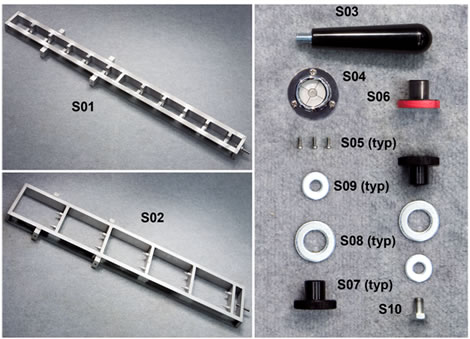
Figure 117. Photo. Equipment for calibration stand assembly.
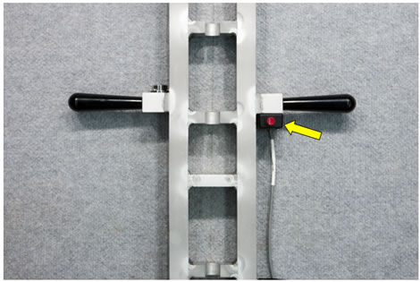
Figure 118. Photo. Calibration stand with handles, bubble level, and pushbutton.
Location of Accelerometer Box
On the geophone calibration stand, the accelerometer box is fastened to a shelf half way up the stand with two #10-24 x ½-inch (12.7-mm) knurled head thumbscrews (S11).
On the seismometer calibration stand, the accelerometer box sits in the middle of the third shelf up on the stand and is held on with two thumbscrews (S11). The accelerometer box needs to be attached before the seismometers to ensure ease of use.
Deflection Sensors
For the geophone calibration stand, there are four different types of geophones that can be calibrated: Carl Bro, Dynatest®, KUAB, and JILS.
The Carl Bro and the JILS geophones are fastened to the stand in similar manners, though they each require their own adapters. The geophone and its respective adapter (S06 and S07) screw together with a ¾-inch (19.05-mm) inside diameter washer (S08) placed between the adapter and shelf of the stand and a 3⁄8-inch (9.53-mm) inside diameter washer (S09) placed between the geophone and the shelf. Figure 119 shows a JILS geophone and adapter fastened to the stand. Carl Bro geophone adapters (S06) have different size threads and are painted red.
The Dynatest® geophones use a magnet to couple to the stand (see figure 120). To accomplish this, the JILS adapter (S07) is turned upside down and fastened to the stand with a 3⁄8-inch
(9.53-mm) to 24 x 5⁄8-inch (609.6 x 15.88-mm) hex head cap screw (S10) as shown in
Figure 121. The Dynatest® geophone then sits on top of the adapter.
The KUAB geophones use a collar (S12), magnet (S13), and modified knob (S14) to attach to the stand, as shown in figure 122 and figure 123. The knobs are painted gold. The modifications to the knob are to drill and tap for a #10-24 machine screw thru the length of the knob, and to
mill out a 1⁄8-inch (3.18 mm) deep by 1-inch (25.4-mm) diameter recess at the top of the shank to allow the magnet assembly to fit inside.
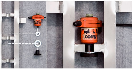
Figure 119. Photo. Attachment of a JILS or Carl Bro geophone to the stand.
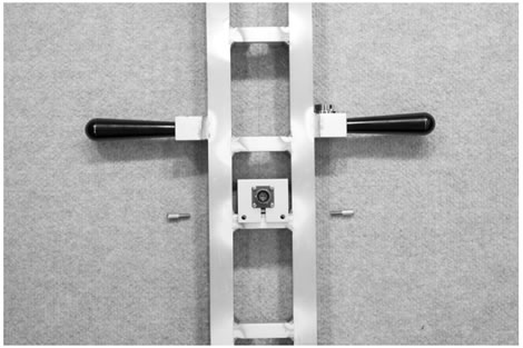
Figure 120. Photo. Placement of the accelerometer box on the geophone stand.
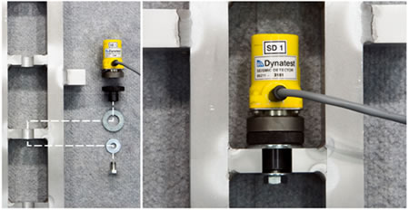
Figure 121. Photo. Attachment of a Dynatest® geophone to the stand.
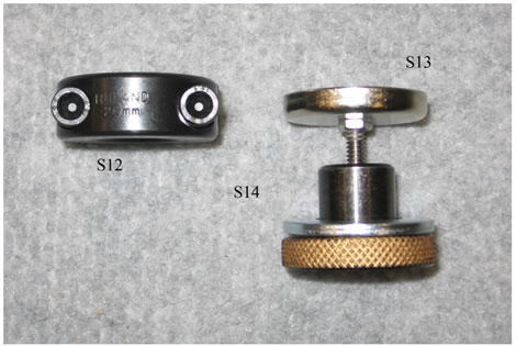
Figure 122. Photo. KUAB geophone adapter equipment.
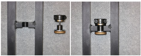
Figure 123. Photo. Attachment of a KUAB geophone adapter.
For the KUAB seismometer calibration stand, the seismometers are aligned in a two-column
configuration as shown in figure 124. Users should tighten the setscrew at the bottom of the
seismometer onto the standoffs on the stand.
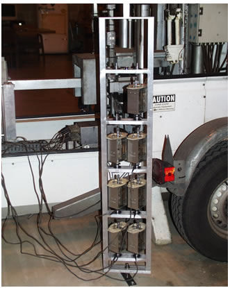
Figure 124. Photo. Seismometer stand with sensors attached.
Using the Stand
During deflection sensor calibration, the calibration stand should be set up in the following order:
- Attach the stand to the ball-joint anchor.
- Fasten the accelerometer box to the stand after the accelerometer has been calibrated.
- Place the deflection sensors in the correct configuration as shown on screen in the
WinFWDCal program.
- Use Velcro® to attach the pushbutton to the stand.
The following procedure is used when going from one trial to the next in relative and reference calibration:
- For Dynatest® geophones, remove the sensor by tilting its casing until the magnetic force is reduced enough to pull it out of the stand. Never pull on the sensor’s wiring to remove it.
- For the Carl Bro and JILS geophones, loosen the adapter by unscrewing it to a point where the adapter/sensor combination can be slid out of the stand as a unit.
- For KUAB geophones, remove the sensor and collar by tilting the casing until the magnetic force is reduced enough to pull it out of the stand. Never pull on the sensor’s wiring to remove it.
- For KUAB seismometers, do not move the sensors in the stand. Simply rotate the stand horizontally about the connecting pin 180 degrees.
To couple the stand to the ball-joint, use the following:
- For both calibration stands, the connector pin slides into the clamp as shown in
figure 125. The clamp is then tightened so that the stand cannot be removed.
- It is very important that the pin extending from the calibration stand is tightly fixed in the
stand. Use several drops of Loctite® on the threads to assure that the pin does not come
loose. Doing so will reduce the variability of the deflection data that is collected.
- The screws holding the pin in the clamp must be tightened firmly. The two bolts that hold
down the ball-joint anchor to the floor must also be tight. However, do not use Loctite®
on these connections.
- Finally, the two screws that adjust the ball-joint friction must be set so the calibration
stand will stay upright when it vertical and not held, but a small tap horizontally will
cause the stand to fall over easily to the rest stop.
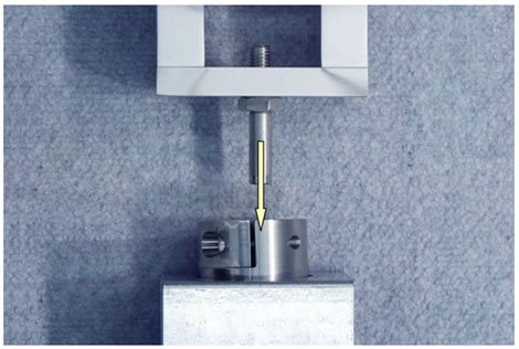
Figure 125. Photo. Coupling the calibration stand and ball-joint anchor.
DATA ACQUISITION SYSTEM
Parts and Tools
Table 46. Parts and equipment for data acquisition.
| No. |
Tool/Equipment |
Quantity |
Notes |
| USB |
Standard USB cable |
1 |
|
| D01 |
Vishay to KUSB DAQ cable |
1 |
Drawing CLRP-DAQ01 |
| D01A |
Vishay 2310B to KUSB DAQ
cable |
1 |
Drawing CLRP-DAQ01A |
| D01B |
Vishay 2310B to DAQ cable
(stock parts) |
1 |
Drawing CLRP-DAQ01B |
| D02 |
Vishay to load cell cable |
1 |
Drawing CLRP-DAQ02 |
| D03 |
Accelerometer signal cable |
1 |
Drawing CLRP-DAQ03 |
| D04 |
Pushbutton to KUSB DAQ
cable |
1 |
Drawing CLRP-DAQ04 |
| D05 |
Keithley KUSB-3108 16-bit
DAQ |
1 |
|
| D06 |
Vishay 2310 signal
conditioner |
1 |
|
Note: Blank cells indicate no notes area available. |
Cable Assembly
All cables should be fabricated according to their respective drawings. A full set of calibration cables includes an accelerometer signal cable (D05), a load cell signal cable (D04), a Vishay to KUSB DAQ cable (D03), and a pushbutton assembly (D06).
Connection Breakdown
Figure 126 illustrates FWD data acquisition system components and connections. The following list explains the connection breakdown:
- Calibration center personal computer to Keithley KUSB-3108 DAQ USB: Use a standard USB cable and plug into an available USB 2.0 port on the calibration computer.
- Vishay to KUSB DAQ cable (D01): Refer to drawing CLRP-DAQ01 for information on how to connect the signal cable to DAQ. The Molex® connector (serial number (s/n)
38331-5608) plugs into the output receptacle in the back of the signal conditioner.
- Vishay to load cell cable (D02): The Amphenol 15-pin plug (s/n PT06A-14-15P
<SR>
) end of the load cell signal cable (drawing CLRP-DAQ02) connects to the input receptacle on the back of signal conditioner. The Amphenol five-pin plug (s/n MS3106A 14S-5S) end of the cable connects into the receptacle on the load cell.
- Vishay to accelerometer cable (D03): The Amphenol 15-pin plug (s/n PT06A-14-15P
<SR>) end of the accelerometer signal cable (drawing CLRP-DAQ03) connects to the input receptacle on the back of signal conditioner. The Amphenol six-socket plug (s/n PT06A-10-6S <SR>) end of the cable connects into the receptacle on the accelerometer box.
- Pushbutton to KUSB DAQ cable (D04): Refer to drawing CLRP-DAQ04 for information on how to connect the pushbutton to DAQ.
Figure 126. Illustration. FWD data acquisition system components and connections.
Vishay 2310 Signal Conditioner Settings
Table 47. Settings for the Vishay 2310 signal conditioner.
| Vishay 2310 Setting |
Load Cell |
Accelerometer |
| Excitation |
10 V |
10 V |
| Filter |
1 kHz |
1 kHz |
| Gain |
Load cell dependant1 |
2.0 x 1 |
| Auto balance |
Procedure dependant2 |
Always off |
| AC in |
Fully extended |
Fully extended |
1Indicates that each calibration center is provided with the correct gain for its reference load cell from the annual calibration.
2Indicates that during the FWD load cell calibration, WinFWDCal provides instruction for when to use the auto balance switch on the Vishay signal conditioner.
|
COMPUTER
Table 48 presents the minimum requirements for a calibration computer. A laptop is recommended for portability.
Table 48. Minimum requirements for computer hardware.
| Item |
Requirement |
| Operating system |
Microsoft Windows XP® SP3 or
later (not including Windows 7®) |
| Physical memory (RAM) |
1 GB |
| Hard disk space |
At least 25 GB free space |
| Video adapter |
DVI/VGA |
| Display |
17-inch external color monitor
(15-inch liquid crystal display on laptop) |
| Optical drive |
CD-RW (DVD ±RW preferred) |
| Removable storage |
3.5-inch floppy disk drive and
256 MB USB flash drive |
| USB 2.0 ports |
At least four |
| Printer |
Inkjet or laser |
1 inch = 25.4 mm
Note: The USB flash drive, 3.5-inch floppy drive, and CD writer are used for transferring data between the FWD computer and the calibration computer. |

