Alternative Intersections/Interchanges: Informational Report (AIIR)
CHAPTER 5. QUADRANT ROADWAY INTERSECTION
5.1 INTRODUCTION
A QR intersection is a promising design for an intersection of two busy suburban or urban roadways. The primary objective of a QR intersection is to reduce delay at a severely congested intersection and to reduce overall travel time by removing left-turn movements. A QR intersection can provide other benefits as well, such as making it shorter and quicker for most pedestrians at the intersection. A QR intersection can be among the least costly of the alternative intersections to construct and maintain.
At a QR intersection, all four left-turn movements at a conventional four-legged intersection are rerouted to use a connector roadway in one quadrant. Figure 126 shows the connector road and how all four of the left-turning movements are rerouted to use it. Left turns from all approaches are prohibited at the main intersection, which consequently allows a simple two-phase signal operation at the main intersection. Each terminus of the connector road is typically signalized. These two secondary signal-controlled intersections usually require three phases.
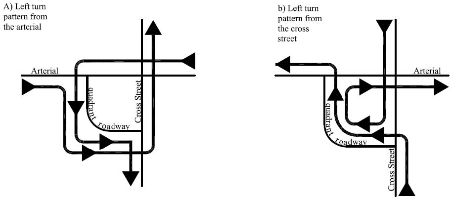
Figure 126. Illustration. Left-turn movements at a QR intersection.
Analyses have shown that a QR intersection is an efficient design at many levels of traffic demand but especially at an intersection with high through volumes and low to moderate left-turn volumes. The reason for this efficiency lies in the conversion of the signal at the main intersection from multiple to two phases. The QR intersection is also aided by the easy coordination that is possible between the main signal-controlled and the secondary signal-controlled intersections. Similar to other alternative designs covered in this report, most through drivers on the main and side roads do not have to stop at each set of traffic signals they encounter if the signals are operated in a coordinated system.
In the United States, there have been many intersections where left turns have been prohibited and redirected on connecting roads in existing signal-controlled street networks. The signs are typically installed to direct drivers who would normally turn left at the major intersection to turn left at a secondary intersection upstream from the major intersection. This form of traffic control treatment has been implemented to reduce congestion and increase capacity at the major intersection by removing at least one left-turn movement and the associated signal phase from the congested intersection. The primary difference between this type of treatment and the QR intersection in its pure form is that all left turns are removed from the major intersection of the QR intersection.
At the time that this report was prepared, the authors were unaware of any location in the United States that fully met the definition of a QR intersection with all four left turns using the connecting road, all left turns prohibited at the main intersection, and the three signals fully coordinated. The full QR intersection concept was first published by Jonathan Reid in 2000. (66) He explored the concept in a subsequent paper and in his paper on unconventional intersections. (61) Since then, the QR intersection concept has been explored by others (such as by FHWA in 2004). (49)
5.2 GEOMETRIC DESIGN CONSIDERATIONS
This section discusses the geometric design of the QR intersection, specifically choosing a quadrant in which to locate the connecting roadway, determining the number of connecting roadways, and designing the main intersection, the secondary intersections, horizontal alignment, and the cross section of the connecting road.
5.2.1 Quadrant Selection
QR intersection designs with one connecting roadway in one quadrant are likely the most common application, as these perform well operationally and minimize the construction and right-of-way costs compared to designs with more than one connector roadway. For one-connector designs, a critical question is which quadrant should have the connector roadway. In some cases, there is available right-of-way in just one quadrant, which makes the decision easy. In other cases, there may be an opportunity in one quadrant with the chance to integrate the connector roadway into the development, making the decision easy as well. As part of an improvement project to realign a skewed intersection, the opportunity may exist to construct connector roads in two of the quadrants.
The most difficult cases in which to make the decision on where to locate the connector road are with 90-degree intersections and with quadrants that do not have particular cost or development advantages. In these cases, the deciding factor may be the left-turn demands. One of the left-turning maneuvers (as shown in figure 126) has to make three right turns, travel through the main intersection twice, and travel the longest distance of any maneuver at the intersection. The connector roadway could be placed in these cases such that this maneuver is made by the left turn with the lowest demand. Conversely, one of the left-turning maneuvers does not have to travel through the main intersection at all and requires no greater travel distance than at a conventional intersection. The connector roadway could be placed such that the left turn with the highest demand is the one that receives the most direct path. It is important to recognize that conceptually a QR-like intersection could be created without the construction of a new roadway connector if there were existing streets to serve the function.
5.2.2 QR Intersections with Multiple Connector Roadways
Reid’s idea was for a single connecting roadway in one intersection quadrant. (66) Most of this chapter is devoted to the analysis of that idea. However, an extension to Reid’s idea worth noting is an intersection with connecting roadways in two or more quadrants. This subsection briefly explores those extensions.
A design with two connecting roadways could offer advantages over the single-quadrant design. The two connecting roadways would most likely be placed on diagonal quadrants as seen in figure 127 to avoid the need for a fourth signal phase at any of the secondary signal-controlled intersections. Two connecting roadways offer the chance for every left-turn maneuver to be initiated from the left side of the street. This avoids the violation of driver expectations inherent in the single-quadrant design wherein two of the left turns are initiated from the right side of the roadway. With the two-quadrant design, two of the left turns have to travel through the main intersection before turning, which could also violate some driver expectations. Two-quadrant designs should perform better operationally than single-quadrant designs carrying the same demands, assuming that good signal progression can be arranged through all five signals. Other drawbacks of the two-quadrant designs are the potential additional right-of-way required, the additional construction costs and maintenance costs, and the additional street crossings that pedestrians have to negotiate.
As noted earlier, the selection of multiple connector designs may be facilitated by the existence of streets in the network that could serve the function. In many urban street networks, connectors may exist in two or more quadrants. In these cases, it will be necessary to determine if the connecting streets have the capacity and sufficient design standards to accommodate the rerouted traffic.
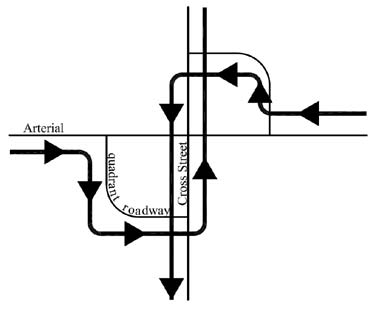
Figure 127. Illustration. Intersection with connector roadways in two quadrants.
Intersection designs with connecting roadways in three or four quadrants are also possible. The success of any three-or four-quadrant design would depend heavily upon the efficiency of the secondary signal operations. If the secondary signals require four phases or long signal phases, then the design’s advantages of minimizing the time and number of phases at the main intersection would be lost. Three-quadrant and four-quadrant designs require more right-of-way and have higher construction and maintenance costs than single-quadrant designs.
5.2.3 Main Intersection
At a QR intersection, the design of the main intersection would be similar to that of a conventional intersection with turn prohibitions. Appropriate pavement markings or median designs should be employed to convey the message to drivers that no left turns or U-turns are allowed. Right-turn lane criteria are the same for a QR intersection as a conventional intersection except for the right turns in the quadrant with the connecting roadway. Right-turn demands do not change at the main intersection in the other three quadrants. Through volumes at the main intersection are higher in all four directions than at a conventional intersection because of rerouted left-turning traffic. Pedestrian crosswalks would normally be provided across all four approaches at the main intersection.
5.2.4 Secondary Intersections
The distance from the main to the secondary intersections is critical to the success of a QR intersection design. The considerations and trade-offs are similar to those between the main intersection and U-turn crossovers for an MUT intersection (chapter 3) or a RCUT intersection (chapter 4). The distance needs to be sufficient to provide adequate vehicle storage and prevent spillback from one signal-controlled intersection to the next. There also needs to be enough spacing to provide room for adequate signing and to ensure that each set of signal control is visible. Longer distances mean higher costs for right-of-way, construction, and maintenance of the connecting road. Longer distances may restrict progression from one signal to the next on the main streets. More importantly, longer distances can translate into more vehicle-hours of travel.
There are additional factors to consider when deciding on the distance from the main to the secondary intersections. One factor is the economic viability of the parcel contained within the connecting roadway. If the parcel is small, then it may be too small for many commercial uses. Another factor to consider is the design speed of the connecting road. If the size of the parcel is too small, there may not be enough area to fit a horizontal curve with an adequate radius, and transitions for the speed that motorists would likely expect to travel on the connecting roadway.
Considering all of the above, a spacing of 500 ft from the center of the main intersection to the center of the secondary intersections appears adequate as a minimum for many situations. This spacing is in line with Reid’s recommendation and with the main intersection to crossover spacing recommended in chapters 3 and 4 for MUT intersections and RCUT intersections. (66) The chances of spillback should be minimal for that distance between signals and moderate cycle lengths. At 40 mi/h on the main street, the offset between signals spaced 500 ft apart is under 9 s, which should not adversely impact progression. With 500-ft spacing between the main and secondary intersections and 90-degree intersection angles, there is sufficient area to fit a curve radius to meet a reasonable 30 mi/h design speed on the connecting road. Assuming typical cross sections, the size of the parcel inside the connecting roadway would be about 3.5 to 4.0 acres, which is viable for a small commercial enterprise.
One critical point about the design of the secondary intersections is that the signal phase duration
required by the connecting road should be minimized to allow more green time for the main
street approaches. In practice, this would likely mean not allowing a fourth leg at the secondary
intersections. Driveways and side streets should not be installed directly opposite the connecting
roadway.
The design of the secondary intersections should include appropriate pavement markings.
Median designs should be employed to convey the message to drivers that U-turns are not
allowed and that left turns are not allowed for one approach. Right-turn lanes should be strongly
considered, as the demands would be boosted by the presence of rerouted left-turning vehicles.
Reid showed a connecting roadway with three lanes, allowing dual left-turn lanes from the
connecting roadway to the main streets at both ends to help keep those phases short. (66) Pedestrian crosswalks would normally be provided across all three approaches at th e
secondary intersections.
5.2.5 Horizontal Alignment
Alignment design for the connecting roadway may present a challenge. The designer will want to provide as gentle a curve as possible, while ending the curve and its transitions before the intersections at both ends. The designer will also want to provide good opportunities for driveway connections to the parcel inside the connecting roadway.
As mentioned above, a 500-ft spacing between the main and secondary intersections is associated positively to a design speed of 30 mi/h on the connecting roadway at a 90-degree intersection. Table 22 provides the relevant geometric design data from the AASHTO Green Book for a design speed of 30 mi/h. (7) The radii and runoff lengths are minimum values, and the radius should be applied to the inside edge of the roadway as recommended by AASHTO.
Table 22. Connecting roadway geometric data for 30 mi/h design speed.
| Superelevation (percent) |
Radius (ft) |
Runoff Length (ft) |
| -2 |
333 |
0 |
| 0 |
300 |
0 |
| 2 |
273 |
45 |
| 4 |
250 |
91 |
A 30 mi/h design speed on the connecting road should be appropriate in many circumstances. Higher design speeds may lead to more difficulties with sight distances to the intersections and the back of the queues.
5.2.6 Connecting Road Cross Section
As mentioned previously, Reid originally presented the QR intersection connecting road with a three-lane cross section. (66) This allowed dual left-turn lanes at each end and a two-way left-turn lane serving driveways in the middle. Three 12-ft-wide lanes with curbs, gutters, and sidewalks on both sides likely require approximately a 60-ft-wide right-of-way and leave an economically viable parcel inside the connecting roadway. This cross section allows only single left-turn lanes from each main street onto the connecting roadway. To further increase that capacity, designers could use a four-lane or five-lane cross section for the connecting roadway. Figure 128 shows a QR intersection with a four-lane connecting roadway. The right-of-way widths and costs grow proportionally for the wider connecting roadways, but the delay savings and other benefits may be worthwhile in some cases.
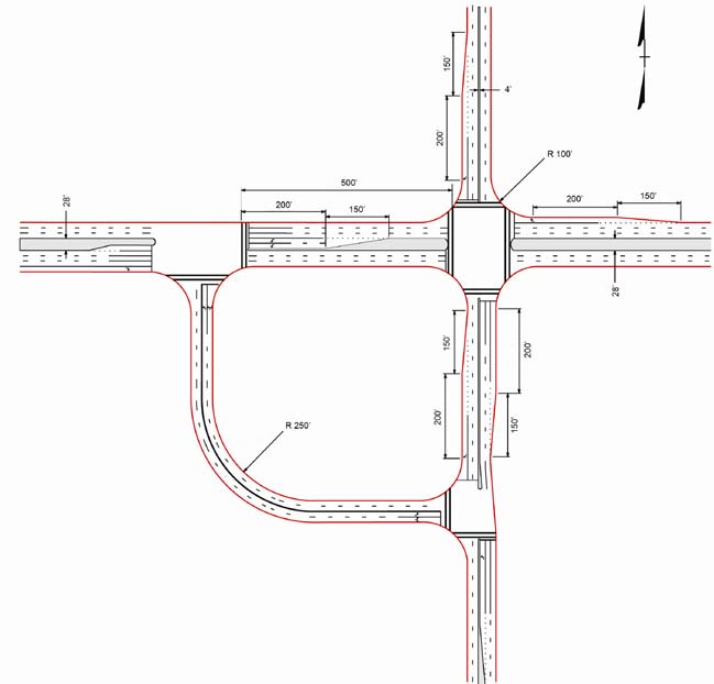
Figure 128. Illustration. QR intersection with four-lane connecting roadway.
5.3 ACCESS MANAGEMENT CONSIDERATIONS
Designers who are considering QR intersections have to be conscious of the impacts on access. As with conventional intersections, limiting access in the vicinity of the main intersection has positive benefits on capacity, quality of flow, and safety. If there are medians or raised median islands on the major road and crossroads at the major intersection, they should be retained when a QR intersection is implemented. If none exist before implementation, then they should be considered for installation as part of the design of the QR intersection.
The removal of the left-turn lanes at the major intersections allows for wider medians to be created within the immediate vicinity of the major intersection. Driveways that allow only right turns in and right turns out offer operational and safety benefits compared to full access driveways.
Access to local parcels is affected by the location and design of the connector, the spacing from the main intersection to the secondary intersections, and the size of the parcel created in the quadrant by the connector road, assuming the connector road is constructed as part of the QR intersection as opposed to utilizing existing streets. Conceivably, access to the parcel in the quadrant could be provided via driveways on the main road, the crossroad, and the connector road. All the driveways could be designed to be right in and right out. However, this may limit accessibility of the parcel from some directions. For example, consider a connector roadway in the southwest quadrant. If the connector roadway is designed with a raised median, then drivers approaching from the east will not have direct access to the site. Consequently, a break in the median on the connector road may be desirable to provide full access to parcel.
At a QR intersection, U-turns are not permitted at the main intersection. U-turn movements are possible from every direction at a QR intersection using the connecting roadway; however, the movements are not straightforward. Drivers would likely need signing or public information programs to learn the path for the U-turn. Thus, a QR intersection may be more applicable to intersections that experience low U-turning volumes.
5.4 TRAFFIC SIGNALIZATION TREATMENTS
A QR intersection has three signal-controlled intersections, including a two-phase signal-controlled main intersection and three-phase signalized intersections at the ends of the connecting road. These are shown in figure 129. While the design of the individual signals is straightforward, the main challenge in the signal design for a QR intersection is how traffic can be progressed through the signals most efficiently.
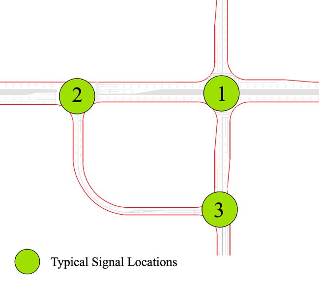
Figure 129. Illustration. Typical QR intersection signal locations.
5.4.1 Signal Design
Figure 130 shows the signal phasing scheme that Reid suggested to optimize progression. (66) In the three-phase scheme, the green phase for the main street (the east-west street in figure 129) at the main intersection extends through the first two phases. Reid’s scheme allows three of the four major street movements past the first signal that drivers encounter during one phase and past the second signal that they encounter during the next phase. Only the southbound movement in Reid’s scheme move through both signals in only one phase. Reid’s scheme produced positive operational results based on simulations comparing QR intersections to other designs. (66)
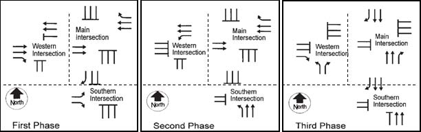
Figure 130. Illustration. Reid’s suggested QR intersection signal phasing scheme. (66)
Reid’s signal phasing scheme assumes that one of the intersecting streets has a higher demand and deserves more green time at the main intersection than the other intersecting street. If this is not the case such that the two major streets carry relatively equal travel volumes, then a slight modification to Reid’s scheme may be beneficial for signal phasing.
When geometry of the intersection is such that the quadrant intersections are so far away from the main intersection that using the same controller to operate signals at all three intersection is not practical or feasible, then the three signalized junctions could be operated by separate controllers. In such a situation, the phasing scheme would be as depicted in figure 131. Figure 132 shows the detector placements for this phasing scheme.
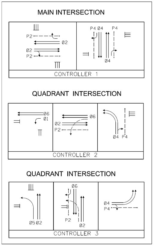
Figure 131. Illustration. QR intersection signal phasing scheme for separate controllers.
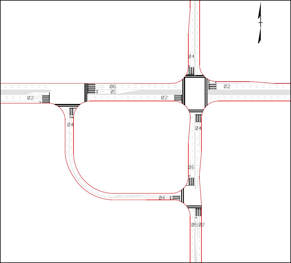
Figure 132. Illustration. Detector locations for QR intersection for signal phasing in figure 131.
A QR intersection gains its relatively good efficiency in large part from the ability to use shorter cycles than a conventional intersection. If analysis begins to suggest that longer cycles are needed for a QR intersection, designers should question whether a different intersection design might better serve the location. The three signalized junctions would require signal equipment including signal poles, mast arms, or span wire. Figure 133 shows one possible set of locations for mast arm signal poles and signal heads. In addition, locations with significant pedestrian volumes would require pedestrian signal heads and actuation.
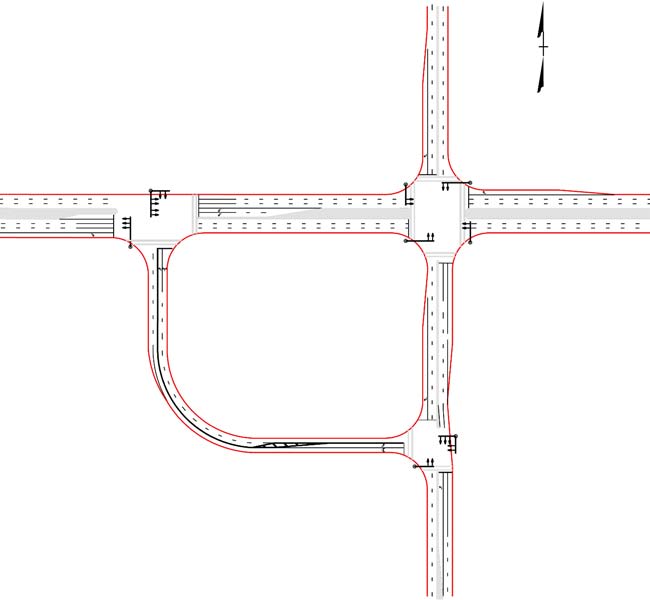
Figure 133. Illustration. Possible signal pole and mast arm locations for QR intersection.
5.4.2 Signing and Marking
The key signing issue at a QR intersection is to convey to drivers where they need to execute left-turning maneuvers. All four left turns are made in different locations compared to where they are made at traditional intersections. As figure 126 shows, two of the left turns at a QR intersection require a driver to first turn right. Advanced guide signing and guide signing at the secondary intersections are needed to lead unfamiliar motorists through a QR intersection.
Figure 134 shows a possible signing plan for a QR intersection. The plan combines features from the standard signing plans that the New Jersey Department of Transportation (NJDOT) uses for jughandle intersections where left turns are initiated from the right side of the road and from signing plans that MDOT uses for MUT intersections where left turns are initiated beyond the main intersection.
At QR intersections with high volumes, high speeds, cluttered roadsides, or other unusual conditions, designers should consider the need for overhead guide signing. Agencies employ overhead signs in some cases to reinforce the messages from standard ground-mounted signs. However, overhead signs add to project costs. The NJDOT and MDOT have found that they can provide adequate information to motorists via ground-mounted signs in a majority of their alternative intersections.
Additional traffic control devices needed at QR intersections include pavement markings, regulatory signs, and warning signs. Adequate pavement markings and regulatory signs complement median nose design and occasional enforcement to ensure that no left turns or U-turns are made at the main intersection. As mentioned previously, speed limit signs, curve warning signs with advisory speeds, and chevron signs can be deployed to convey messages about appropriate speeds. The “Signal Ahead” (W3-3) signs may also be appropriate on the connecting roadway since there may be limited visibility of the signal heads or the back of the queue. (8)
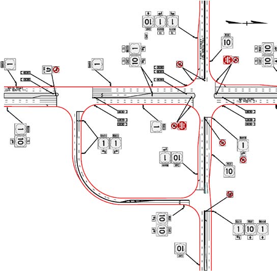
Figure 134. Illustration. Possible signing plan for QR intersection.
5.5 ACCOMMODATION OF PEDESTRIANS, BICYCLISTS, AND TRANSIT USERS
This section presents information on QR intersections with respect to pedestrians, bicyclists, and buses.
5.5.1 Pedestrians
At a QR intersection, some pedestrians have to cross an extra street to make a desired movement compared to a conventional intersection. At a QR intersection, only four movements have to cross an extra street (as compared to a conventional intersection) to reach their outbound sidewalk. As shown in figure 135, the extra crossings are for eastbound and westbound pedestrians at crossing F and for northbound and southbound pedestrians at crossing I.
Pedestrians may find it easier to cross a QR intersection than a comparable conventional intersection because a QR intersection has only two or three signal phases at the intersections. Shorter cycle lengths at QR intersections reduce pedestrian delay. Some pedestrians may have shorter walking distances due to the curved connecting roadway. The paths of pedestrians conflict with right-turning vehicle paths similar to the conflicts at a conventional intersection. Crosswalk lengths may be shorter than at comparable conventional intersections since there are no left-turn lanes at the main intersection.
Designers should be aware of a potential issue at QR intersections with timing signals for pedestrians crossing the main streets at the secondary intersections. Accommodation of pedestrian movements is desirable across all legs to encourage pedestrian mobility. The potential issue at QR intersections relates to the conflict between pedestrians crossing paths H and G and traffic turning left from the connector roadway as shown in figure 135. Signal designers should be concerned about providing appropriate signal displays that are in compliance with the MUTCD. (8) This conflict may reduce the saturation flow rate of the left-turn lane group from the connecting roadway. To accommodate concurrent pedestrian movement during the signal phase serving that left turn, a large portion of the cycle may be needed. Designers concerned with this potential should estimate the pedestrian crossing volume at the points shown in figure 135, perform highway capacity calculations to estimate the effects on LOS and signal timing, and decide whether to remove the pedestrian crosswalk at locations G and H or provide an exclusive pedestrian phase. It would likely take a crossing pedestrian volume of several hundred people per hour to justify an exclusive pedestrian phase.
The secondary signal-controlled intersections in a QR intersection are conventional. Consequently, the treatments are similar to conventional intersections for pedestrians with disabilities. The QR intersection characteristics that contribute to an easier crossing described previously will also assist pedestrians with visual or cognitive disabilities.
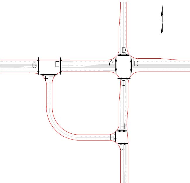
Figure 135. Illustration. Crosswalks at a QR intersection.
5.5.2 Bicyclists
Most bicyclists should find a QR intersection easier to negotiate than a conventional intersection. Through bicyclists on both intersecting streets should experience relatively longer green times and favorable progression. Three of the right-turning movements are unaffected as compared to a conventional intersection, while the fourth has a shorter travel distance using the curved connector roadway. Left-turning bicyclists have a choice of following the vehicular paths and making trips (for three of the four left turns) or following the crossing paths of pedestrians at the main intersection with no extra distance to travel.
5.5.3 Buses
Through and right-turning buses negotiating a QR intersection should experience some operational benefits. Left-turning buses have to travel longer distances and make extra turns, as compared to a conventional intersection, so their operations may suffer. A QR intersection should not affect bus stop placement except in the case of left-turning buses. Spacing the main and secondary intersections 500 ft apart would provide adequate room for a midblock bus stop between those two intersections. The preferred locations of bus stops on the connecting roadway would be on the tangent sections.
5.6 OPERATIONAL PERFORMANCE
The main reason to choose a QR intersection design is to gain operational performance that is better than other intersection designs. This section summarizes two simulation experiments reported in the literature that demonstrate the promise of the QR intersection. The section then presents the results related to QR intersection performance conducted for this study.
5.6.1 Review of Previous Research
Reid introduced the QR intersection concept in 2000 with a paper in the ITE Journal. (66) In the paper, he reported the results of an experiment carried out using the CORSIM ® microscopic simulation package to compare operations between a QR intersection and a conventional intersection. Key features of the QR intersection network used in the experiment were four-lane main streets, a three-lane connector roadway, and a 500-ft spacing between the main intersection and the secondary intersections. The conventional intersection network had dual left-turn lanes on the main street and single left-turn lanes on the cross street. All left turns had protected left-turn phases. Fixed signal timing for the QR intersection was optimized using Synchro ® , while the conventional intersection had a fully actuated signal. (21) Variables examined during the experiment at two levels included intersection type, total volume level, volume split between main and side streets, volume directional split on the arterial, and turn percentage.
Table 23 shows a summary of Reid’s results. (66) The results are averages over all the simulation runs. The most important result is the 15 percent reduction in overall system travel time for the QR intersection. Delays and maximum queue lengths were reduced markedly with the QR intersection, and left-turn travel times only increased marginally for the QR intersection. Analysis of the variable interactions showed that the QR intersection had larger reductions n travel time when the overall demands were highest at about LOS E for the conventional intersection and surprisingly when the left-turn volumes were higher.
Table 23. Simulation experiment results.
| Measure |
Conventional |
QR Intersection |
Percent Difference |
| Cycle length (s) |
142 |
90 |
-58 |
| System delay (veh-h) |
35.8 |
24.4 |
-46 |
| System travel time (veh-h) |
66.9 |
58.2 |
-15 |
| Stops/vehicle |
0.71 |
0.78 |
+9 |
| Speed (mi/h) |
23.4 |
27.2 |
+14 |
| Maximum queue (veh) |
23.4 |
12.4 |
-88 |
| Westbound left-turn travel time, (s/veh) |
120.9 |
125.6 |
+4 |
| Eastbound through travel time (s/veh) |
86.6 |
66.5 |
-30 |
| Main intersection delay (s/veh) |
41.2 |
13.5 |
-215 |
| Main intersection LOS |
E |
B |
Not relevant |
Reid and Hummer performed another CORSIM ® experiment examining the QR intersection and other designs. (61) They simulated seven actual intersections ranging from a four-lane street intersecting a two-lane street to an eight-lane street intersecting a four-lane street. For each intersection, they simulated three demand levels: off peak, peak, and peak plus 15 percent. The researchers optimized the fixed-time signal timings for each design. The results showed that in all cases but one (i.e., in 20 of the 21 cases simulated), the QR intersection produced lower system travel times than the conventional design. In the one case where the conventional was better (i.e., the off peak at the intersection of a six-lane highway and a four-lane highway), the difference was 1 veh-h (74 to 73 veh-h). In the 20 cases in which the QR intersection was superior, the difference was estimated to be as high as 50 veh-h. Reid and Hummer also reported percent stop results from their simulations. (61) The conventional intersection produced a lower percent stop than the QR intersection in 15 of the 21 cases simulated. The QR intersection had lower percent stops in five cases.
5.6.2 Analysis of Simulation Results
New analyses were conducted to demonstrate how the design of the QR intersection affects capacity. In this analysis, a CLV spreadsheet was used to compare the capacity of major and minor approaches for different configurations of a QR intersection.
Key features of the QR intersection used in the experiment were the number of through and left-turn lanes on the major and minor approaches, as well as the number of left-and right-turn lanes on the connector road. The distribution of the volume on the major road was varied between 50:50 and 75:25 for each of the scenarios. For all scenarios, it was assumed that a constant right-turn volume of 300 veh/h and a constant U-turn volume of 10 veh/h were used. A discussion of the simulation results for all of the geometric design cases is provided as follows. Besides all of the usual VISSIM ® defaults, the following constants were maintained throughout each experiment:
- Optimum fixed signal timing determined using Synchro ®. (21)
- Yellow times determined using ITE policy.
- All-red times determined using ITE policy.
- A total of 2 percent heavy vehicles on all legs.
- A total of 300-ft left-turn and right-turn bay lengths in the entire network.
- A 0.5-mi network size in each direction from the main intersection.
- Single right-turn bays on the mainline.
- Right-turn on red allowed at each signal, no left-turn on red allowed.
- A signal at each displaced left-turn crossover.
- A 40-ft median width on mainline.
- Undivided side street.
- A 45 mi/h desired speed on mainline.
- A 25 mi/h desired speed on side street.
- A 30 mi/h desired speed on connector roadway.
- No bus stops.
The four cases modeled included the following:
- Intersection of four-lane, two-way major road, two-lane, two-way minor road with one left-turn lane on the mainline, and a two-lane, two-way connector roadway.
- Intersection of four-lane major road, four-lane minor road with one left-turn lane on the mainline, and two-lane connector roadway.
- Intersection ofsix-lane major road, four-lane minor road with one left-turn lane on the mainline, and two-lane, two-way connector roadway.
- Intersection of six-lane major road, four-lane, two-way minor road with two left-turn lanes on the mainline, and four-lane, two way connector roadway.
These four cases are summarized below in table 24.
Table 24. Geometric design cases of quadrant intersection.
| Case |
Major Road Approaches |
Minor Road Approaches |
Connector Road Approaches |
| Through Lanes |
Left-Turn Lanes |
Through Lanes |
Left-Turn Lanes |
Left-Turn Lanes |
Right-Turn Lanes |
| A |
2 |
1 |
1 |
1 |
1 |
1 |
| B |
2 |
1 |
2 |
1 |
1 |
1 |
| C |
3 |
1 |
2 |
1 |
1 |
1 |
| D |
3 |
2 |
2 |
2 |
2 |
1 |
Figure 136 through figure 139 show the comparison of throughput and average intersection delay for the four geometric design cases (see table 24) of QR and conventional intersections.
For case A with two through lanes on the major road approach and a single through lane on the minor road approach, the conventional intersection performs slightly better compared to the QR intersection. For case B with two through lanes on the major and minor road approaches, the conventional intersection was similar in operational performance compared to the QR intersection. For case C with three through lanes on the major approaches, two through lanes on the minor road approach, and a single lane connector roadway approach, the QR intersection was similar in operational performance compared to the conventional intersection. For case D with three through lanes on the major approaches, two through lanes on the minor road approaches, and a two-lane connector roadway approach, the QR intersection was significantly better than the conventional intersection in operational performance.
Simulation results showed that the QR intersections performed comparably to the conventional intersections for moderate and balanced through volumes on the major road. However, the QR intersections had higher throughput and lower travel times compared to the conventional intersections for scenarios with heavy through and moderate left-turn volumes on the major road and heavy through and left-turn volumes on the minor road. For such scenarios, the increase in throughput ranged from 5 to 20 percent with a 50 to 200 percent savings in travel times.
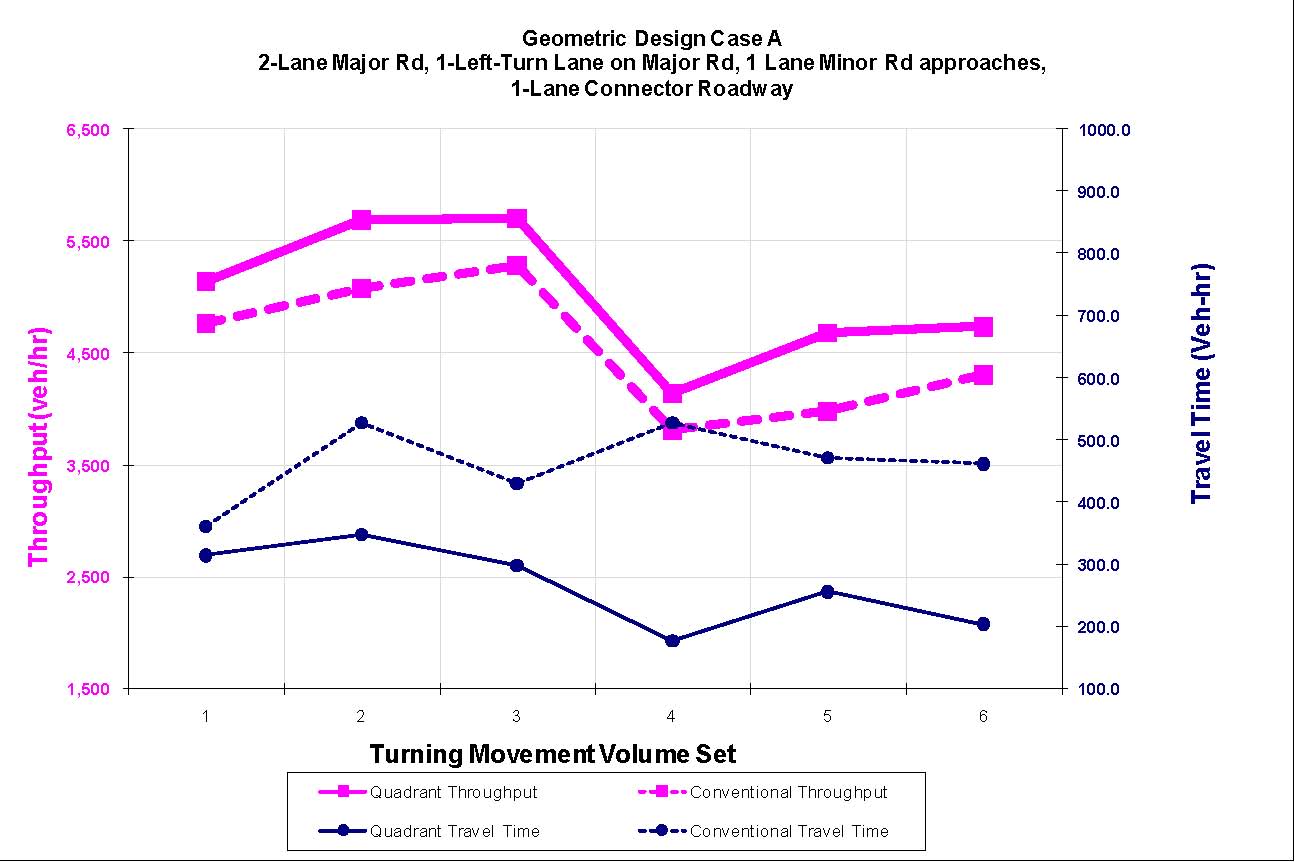
Figure 136. Graph. Throughput and travel time comparisons for geometric design case A.
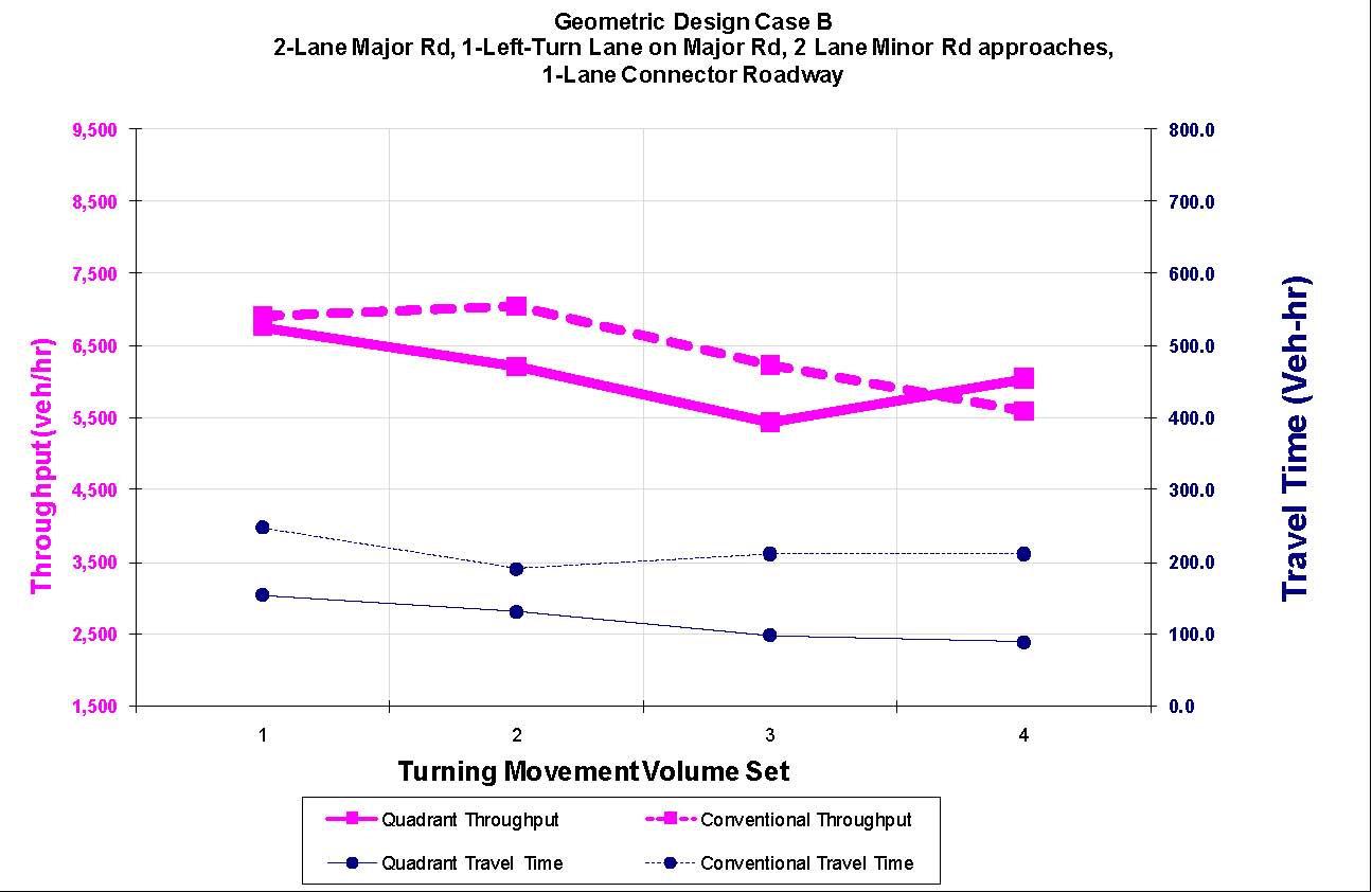
Figure 137. Graph. Throughput and travel time comparisons for geometric design case B.
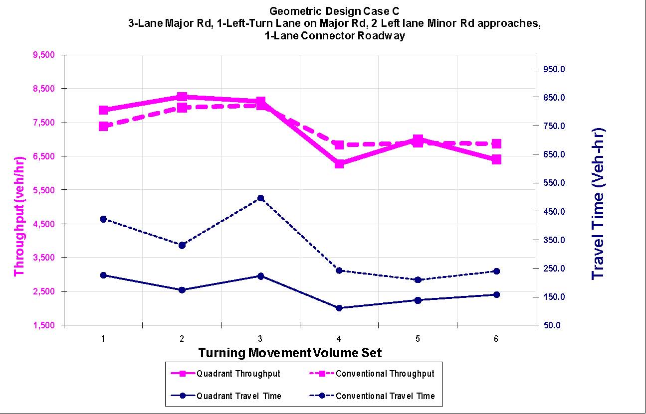
Figure 138. Graph. Throughput and travel time comparisons for geometric design case C.
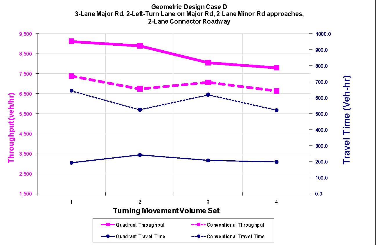
Figure 139. Graph. Throughput and travel time comparisons for geometric design case D.
Table 25 shows the geometric design cases with the turning volumes sets that were simulated in VISSIM ® for the high-volume scenarios.
Table 25. Volumes and QR intersection configurations for VISSIM
®
simulations.
| |
Geometric Cases |
Split |
Input Volumes |
| Major Road |
Minor Road |
Total Input |
| Left |
Thru |
Right |
Left |
Thru |
Right |
| A |
Quadrant |
Two thru and one left on major road, one thru on minor road, and one-lane connector roadway |
50:50 |
210 |
1,200 |
300 |
260 |
350 |
250 |
5,140 |
| 210 |
1,600 |
300 |
260 |
350 |
250 |
5,940 |
| 310 |
1,600 |
300 |
260 |
350 |
250 |
6,140 |
| 30:70 |
210 (90) |
1,200 (514) |
300 (129) |
260 |
350 |
250 |
4,163 |
| 210 (90) |
1,600 (685) |
300 (129) |
260 |
350 |
250 |
4,734 |
| 310 (133) |
1,600 (685) |
300 (129) |
260 |
350 |
250 |
4,877 |
| A |
Conventional |
50:50 |
210 |
1,200 |
300 |
260 |
350 |
250 |
5,140 |
| 210 |
1,600 |
300 |
260 |
350 |
250 |
5,940 |
| 310 |
1,600 |
300 |
260 |
350 |
250 |
6,140 |
| 30:70 |
210 |
1,200 |
300 |
260 |
350 |
250 |
4,163 |
| 210 |
1,600 |
300 |
260 |
350 |
250 |
4,734 |
| 310 |
160 |
300 |
260 |
350 |
250 |
4,877 |
| B |
Quadrant |
Two thru and one left on major road, two thru on minor road, and one-lane connector roadway |
50:50 |
310 |
1,600 |
300 |
210 |
1,100 |
300 |
7,640 |
| 160 |
1,600 |
300 |
210 |
1,100 |
300 |
7,340 |
| 30:70 |
310 |
1,600 |
300 |
210 |
1,100 |
300 |
6,377 |
| 160 |
1,600 |
300 |
210 |
1,100 |
300 |
6,163 |
| B |
Conventional |
50:50 |
310 |
1,600 |
300 |
210 |
1,100 |
300 |
7,640 |
| 160 |
1,600 |
300 |
210 |
1,100 |
300 |
7,340 |
| 30:70 |
310 |
1,600 |
300 |
210 |
1,100 |
300 |
6,377 |
| 160 |
1,600 |
300 |
210 |
1,100 |
300 |
6,163 |
| C |
Quadrant |
Three thru and one left on major road, two thru on minor road, and one-lane connector roadway |
50:50 |
310 |
2,200 |
300 |
210 |
1,100 |
300 |
8,840 |
| 210 |
2,200 |
300 |
210 |
1,100 |
300 |
8,640 |
| 210 |
2,400 |
300 |
210 |
1,100 |
300 |
9,040 |
| 30:70 |
310 |
2,200 |
300 |
210 |
1,100 |
300 |
7,234 |
| 210 |
2,200 |
300 |
210 |
1,100 |
300 |
7,091 |
| 210 |
2,400 |
300 |
210 |
1,100 |
300 |
7,377 |
| C |
Conventional |
50:50 |
310 |
2,200 |
300 |
210 |
1,100 |
300 |
8,840 |
| 210 |
2,200 |
300 |
210 |
1,100 |
300 |
8,640 |
| 210 |
2,400 |
300 |
210 |
1,100 |
300 |
9,040 |
| 30:70 |
310 |
2,200 |
300 |
210 |
1,100 |
300 |
7,234 |
| 210 |
2,200 |
300 |
210 |
1,100 |
300 |
7,091 |
| 210 |
2,400 |
300 |
210 |
1,100 |
300 |
7,377 |
| D |
Quadrant |
Three thru and two left on major road, two thru on minor road, and two lane connector roadway |
50:50 |
510 (210) |
2,400 |
300 |
510 |
1,100 |
300 |
9,940 |
| 510 (210) |
2,200 |
300 |
510 |
1,100 |
300 |
9,340 |
| 30:70 |
510 (219) |
2,400 (1,029) |
300 (128) |
510 |
1,100 |
300 |
8,406 |
| 510 (219) |
2,400 (1,029) |
300 (128) |
510 |
1,100 |
300 |
8,006 |
| D |
Conventional |
50:50 |
510 (210) |
2,400 |
300 |
510 |
1,100 |
300 |
9,940 |
| 510 (210) |
2,200 |
300 |
510 |
1,100 |
300 |
9,340 |
| 30:70 |
510 (219) |
2,400 (1029) |
300 (128) |
510 |
1,100 |
300 |
8,406 |
| 510 (219) |
2,400 (1,029) |
300 (128) |
510 |
1,100 |
300 |
8,006 |
Note: The figures in parentheses indicate the directional splits for the major road volumes.
5.7 SAFETY PERFORMANCE
Since a complete QR intersection has not been built as of the preparation of this report, there is no empirical basis on which to draw when making estimates on the expected safety of a QR intersection. Nonetheless, clues about conflicts and from collision models are helpful to make some inferences about QR intersection safety. The number of vehicle-vehicle conflict points is lower at a QR intersection than at a conventional intersection. As described previously in this report, there are 32 vehicle-vehicle conflict points at a conventional intersection, not including U-turns. Figure 140 shows that there are 28 vehicle-vehicle conflict points at a QR intersection. This reduction in conflict points may serve as an indicator of improved safety although research shows no definitive relationship to crash experience.
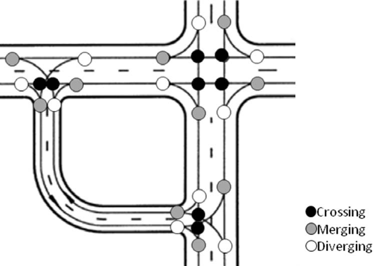
Figure 140. Illustration. Vehicle-vehicle conflict points at a QR intersection. (49)
5.8 CONSTRUCTION COSTS
This section presents a discussion of construction costs for a retrofit of a conventional intersection into a QR intersection with a new connector roadway. Due to the wide-ranging scale, meaningful costs for a QR intersection were not developed for the scenario where a new intersection would be constructed.
Construction costs are likely higher for a QR intersection than a conventional intersection due to the new connector roadway and additional traffic control. The cost of the connector roadway is the largest additional cost compared to a conventional intersection. The connector roadway is about 880 ft (centerline to centerline), or 0.167-mi long, with a 500-ft spacing between the main and secondary intersections. For a three-lane connector road with sidewalks on both sides, the required right-of-way is about 1.1 acres. On a corner in a developing area, that right-of-way could cost from several thousand dollars to over $1 million. The cost to construct the connector roadway varies widely with time, place, and circumstances such as the amount of grading and utilities needed to relocate. Using an order of magnitude cost of $3 million per 1 mi to construct a typical three-lane urban street, it is estimated that the construction cost would be about $500,000 for the connector roadway.
The smaller footprints of the main roads through a QR intersection would provide some construction cost savings relative to a conventional intersection. The smaller footprint would occur primarily because the main streets at a QR intersection need a left-turn lane on only one approach each. The savings from this reduced main street width is likely to be less than $100,000 altogether.
Signal costs are higher at a QR intersection than at a conventional intersection because there are three interconnected signals instead of one. Based on signal costs experienced in North Carolina at recent super street installations (which also may have volumes that warrant three interconnected signals at similar spacing), the additional signal costs at a QR intersection could be over $300,000.
To summarize, the construction costs are likely higher for a QR intersection than a conventional intersection. From the main components adding to the cost (i.e., connector roadway, extra signals, and extra overhead signs), the cost of the connector roadway is the greatest cost and could have a significant impact on the total project cost depending on availability and cost of additional right-of-way. While these higher costs are offset slightly by reduced widths on the main streets, there is an overall increase in project costs for the QR intersection design. The presence of an existing connector roadway on one of the quadrants of the main intersection could be used as the QR intersection connector roadway, resulting in substantial savings in land acquisition costs and complete signalization of the junctions.
5.9 SEQUENCING OF CONSTRUCTION
The complexity of maintenance of traffic during the construction of a QR intersection varies with the situation. An agency can construct the connecting roadway without affecting vehicular traffic on the major streets and can keep operating the main intersection in conventional style. Only the sidewalks crossing the connecting roadway would be affected during its construction, and pedestrian traffic on the sidewalks may have to be rerouted for brief periods. After the connecting roadways open, an agency can close the left-turn lanes at the main intersection and proceed with repaving, median reconstruction, and restriping of the main streets. Agencies need to ensure that all new signs and signals for the QR intersection are covered until the facility is opened so as not to distract or misdirect motorists.
5.10 OTHER CONSIDERATIONS
Agencies considering QR intersection installation should consider issues such as lighting, maintenance costs, enforcement needs, public relations, emergency vehicles, and school bus routing. Lighting is often associated with signalized intersections, particularly in urban and suburban areas. Given that the QR intersection design includes three signalized intersections compared to the single signalized intersection of a conventional design, there is the potential for increased lighting needs. There has been an added safety benefit associated with intersection lighting. These costs for lighting are higher for a QR intersection design compared to the conventional design because the overall junction is larger and made of three intersections. A common drawback to lighting is the expense of running electricity to the luminaries and control box. However, the QR intersection design is applicable mainly in urban and suburban areas where it is likely that the necessary utility lines already exist.
The maintenance costs for a QR intersection are likely higher than for a comparable conventional intersection. Higher costs are due in part to the two extra signals that must be powered and maintained. The connecting roadway also requires extra maintenance.
Enforcement needs at QR intersections may be higher shortly after their opening than at conventional intersections. In Michigan, the approach for opening a new MUT intersection is to allocate additional enforcement resources during the first few weeks of operation to reduce the number of illegal left turns at the main intersection. This may also be appropriate at new QR intersections. Once drivers become familiar with the operation of the intersection, the need for additional enforcement will likely subside, and normal vigilance in enforcing traffic laws on QR intersections should suffice.
To help drivers learn how to use the design, agencies should consider a public information campaign to coincide with the opening of a QR intersection. Press releases, flyers distributed to nearby businesses and residents, and material posted on the agency Web site could help. The information should discuss the need for left-turning motorists to follow the signs. It should also indicate that motorists will experience better intersection operations with the new design. Public information should also instruct pedestrians using the intersection, including discussing transit stop locations, especially if they are being relocated.
Emergency vehicles trying to make left turns at a QR intersection have longer travel times and possibly increased delays than at a conventional intersection. Agencies should therefore consider allowing direct left turns by emergency vehicles at the main intersection. Other than possibly a sharp median nose, there are no physical obstacles to prevent making a direct left turn. Another issue related to emergency vehicles is whether to give the connecting roadway its own street name and address numbers. This is necessary for efficient emergency vehicle response. However, a named connecting roadway complicates signing. It may be prudent to name the connecting roadway only if there are land parcels that are only accessible directly from the connector road.
Like all other intersection users, school buses should generally benefit from reduced travel times through a QR intersection. However, school bus routes that turn left at a QR intersection can generally be lengthened. As mentioned earlier in the report for transit bus stops, school bus stops on the curved portion of the connecting roadway may not be optimum due to driver sight lines to the bus and the back of the queue.
5.11 APPLICABILITY
The QR intersection is intended to reduce travel time through congested intersections in urban or suburban areas. It is a spot treatment at a particular intersection, like the DLT intersection, rather than a treatment that lends itself to application along a corridor, like the MUT and RCUT intersections. Particular conditions that planners and designers should associate with the possibility of a successful QR intersection installation include the following:
- Heavy through volumes: QR intersections are appropriate for intersections with heavy through volumes and low to moderate major road left-turn volumes. However, they have an additional signal for through traffic to pass through. Therefore, if conventional traffic management can provide an adequate peak period LOS, then there is little to be gained from making the extra investment in the QR intersection.
- One high left-turn volume: If only one of the four left-turn movements at the main intersection is heavy and if the connector can be constructed in the quadrant that allows direct left turns onto that connector, then the QR intersection has great promise.
- Moderate or low left-turn volume: A QR intersection is most appropriate for lower left-turn volumes since the intersection design increases travel distances for left-turning vehicles and increases the number of signals to pass through. At some point, the left-turn demands become too high, and the extra travel time for left-turning vehicles exceeds the savings for through vehicles.
- Empty or redeveloping quadrant: The ideal case for a QR intersection exists when a developer is willing to donate right-of-way and build the connector roadway in exchange for the favorable access that the connector roadway provides to adjacent parcels. The right-of-way costs for the connector roadway could be substantial and at some point could be cost prohibitive, forcing planners and designers to choose other intersection options.
- Nearby signals: A QR intersection works well by reducing the cycle length at the main intersection and providing an adequate amount of green time for the main streets. If there are nearby signals along the arterials, then the QR intersection signals should be fairly easy to integrate into a signal system. A single large intersection in the middle of a corridor with otherwise good progression potential might be a candidate for a QR intersection when compared to a conventional, multiphase signal-controlled intersection with a long cycle.
- Future plans for grade separation: QR intersections work well as an intermediate stage between a conventional intersection and interchange. Early in the development of an intersection, a highway agency could operate it as a conventional design while reserving right-of-way in a quadrant for a connector roadway. When demands are high enough to justify it, the agency could build the connector roadway and operate the intersection as a QR intersection. When demands begin to overwhelm the QR intersection, the agency can build a grade separation and either continue to use the connector roadway or integrate the connector roadway into a quadrant interchange, a partial cloverleaf interchange, or some other interchange form. In the intermediate stage, a QR intersection could provide the benefit of efficient operations without the expense of the bridge for the interchange.
- Skewed intersection: A skewed intersection lends itself to a QR intersection in several respects, as it allows a shorter connecting roadway, provides a gentler curve on the connector, and eliminates the need for any drivers to make turns over 90 degrees.
Agencies should not consider a QR intersection unless the through and left-turn demands justify it operationally and unless there is a chance for right-of-way for the connector road to be available at a reasonable cost. The other listed conditions would enhance the positive response to a QR intersection but are not absolutely necessary to its success. In other words, a QR intersection would likely work better relative to other designs in an area with moderate pedestrian demands, but it does not need moderate pedestrian demands to be justified.
In this report, there is an absence of crash experience because safety performance of a complete QR intersection is not known. A well-designed QR intersection may improve intersection safety because of lower conflict points that are more spatially separated in comparison to a conventional intersection.
5.12 SUMMARY
The main objective in employing a QR intersection is to increase operational efficiency through a heavily congested intersection. By moving the left turns away from the main intersection and allowing a two-phase signal, a QR intersection is one of the most efficient at-grade intersection designs discussed in this report. The QR intersection also accommodates pedestrians, allowing an easier crossing and penalizing only 4 of the possible 48 pedestrian movements with an extra street crossing.
The main drawbacks to the QR intersection design are the potential expectancy violations of left-turning drivers, the additional right-of-way needed in one quadrant, and the extra cost to build the connecting roadway. Good signing can help mitigate the violated expectancies of left-turning drivers, but no signing system will reach all drivers at all times. Other designs that require similar maneuvers of left-turning drivers, such as jughandles in New Jersey, function well. The extra right-of-way needed means that the QR intersection would likely be applied more often in developing areas. It is possible that developers would see the advantage of having the connecting roadway integrated into their developments and cooperate with highway agencies in building the connecting roadway. Moreover, the existing roadway network may lend itself to a QR intersection if an existing roadway can be converted to serve the role of a QR intersection’s new connector roadway. The added construction and maintenance costs of the QR intersection are in line with other nonconventional intersections and should always be considered in conjunction with all of the savings in time, energy, and emissions that they provide.
To summarize, the QR intersection can reduce traffic congestion at an intersection in a developing area. It could serve as a temporary solution until a grade-separated solution is funded and built. As QR intersections are built, a safety record can be established, and the questions regarding motorist understanding can be answered more definitively.
|


