Alternative Intersections/Interchanges: Informational Report (AIIR)
CHAPTER 9. OTHER INTERCHANGE CONFIGURATIONS
This chapter presents sketches and briefly describes other types of alternative interchanges.
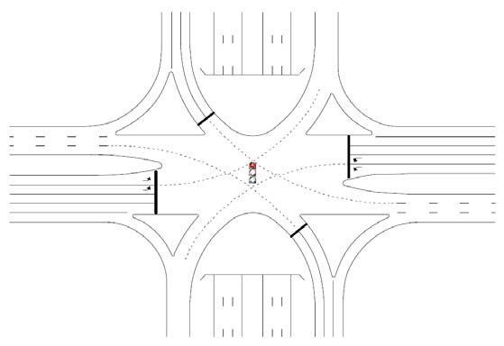
9.1 TIGHT URBAN DIAMOND INTERCHANGE
The TUDI, a type of compressed diamond interchange, is used in urban and suburban areas where right-of-way is a constraint. Figure 197 shows a TUDI, which has two closely spaced signalized intersections at the crossing of the ramp terminals and side street. Typical designs provide 200 to 400 ft of separation between the signal-controlled intersections.(90) Generally, the bridge design of a TUDI has spans between 140 and 180 ft depending on various geometrics of the crossing.(91)

Source: Transportation Research Board
Figure 197. Illustration. TUDI configuration.(92)
The key operational aspect of a TUDI is signal coordination to ensure efficient progression of traffic and minimum storage of vehicles between the terminals.(92) Other traffic flow parameters like saturation flow rate, clearance times, and turning speeds in a TUDI are the same as a conventional at-grade intersection. Typically, a TUDI requires a four-phase signal phasing with overlapping for both intersections.(91)
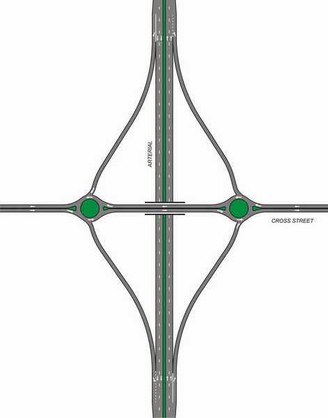
9.2 SINGLE POINT URBAN INTERCHANGE
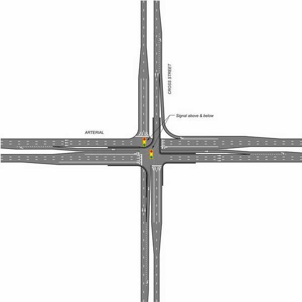
The SPUI, another variant of the compressed diamond interchange, was developed in 1970 to improve traffic capacity and operations while requiring less right-of-way than the diamond interchange.(93) The configuration of a typical SPUI is shown in figure 198. The turning movements of the major road ramps and all the movements of the minor road are executed in one central area that is either on the overpass or underpass.
Some of the key design characteristics that need to be considered when designing a SPUI are skew angle; number of through, left-, and right-turn lanes; median width; and islands.(93) Generally, the bridge of a SPUI has a span length from 160 to 280 ft depending on various geometrics of the crossing. The bridge structure of a SPUI has a large deck and is more expensive to construct in comparison to a TUDI, which is relatively easy to design and construct.(91)
Source: Transportation Research Board
Figure 198. Illustration. SPUI configuration.(92)
The actuated signal controller in a SPUI has the option of having concurrent signal phases to serve the crossroad left-turn movement with the adjacent through movement, as per vehicle detection.(94) Typically, SPUIs can operate on a three- or four-phase signal phasing. Most SPUIs use a single actuated signal controller. With an extremely wide intersection, the SPUI requires longer yellow and all-red clearance intervals compared to a conventional intersection.(94) Additionally, if frontage roads are present, a SPUI may need an additional phase to serve through movements on the ramp.(91)
Existing literature points out that SPUIs increase capacity and therefore accommodate more vehicles compared to conventional diamond interchanges. Since a SPUI has one signalized intersection, it allows for a simpler phasing sequence for signal control. This also makes it easy for a SPUI to be coordinated with upstream and downstream signals. Existing research does not reveal significant differences in the crash statistics between TUDIs and SPUIs of similar geometrics.(95) Since pedestrians normally cross the major road in a path that is parallel to the cross street, conventional and compressed diamond interchanges offer benefits in pedestrian accommodation compared to SPUIs.
9.3 OTHER ALTERNATIVE DIAMOND INTERCHANGES
Grade separation is considered at the intersections of major roadways to reduce congestion and increase capacity. Traditional interchanges including the cloverleaf, partial cloverleaf (Parclo), and the directional interchange require large right-of-ways and are costly and often difficult to construct in urban environments. In addition, urban environments have developments such as offices, retail businesses, and commercial and mixed uses that often abut the highway. Traditional interchanges also restrict driveway access.(96)
Some of these concerns are addressed with the help of designs like the TUDI and SPUI. Alternative interchanges endeavor to further reduce right-of-way requirements and to improve traffic operations and safety. Some of the primary elements of alternative interchange design are as follows:
- A smaller footprint with the help of tighter loop ramp radii, reduced lane widths, shorter weaving areas, and the signalization of nodes of the interchange. Smaller footprint areas usually result in smaller land acquisition costs, thereby minimizing construction costs.
- Use of signalization of the interchange to meter traffic for the downstream intersections on the arterial. This helps if the adjacent signalized intersection in the network cannot handle heavy volumes from traditional interchanges.(96)
- A design for lower speeds, ease of navigation, and increased safety by reduction of conflict points when compared to the TUDI and SPUI.
- Flexibility of design and ease of construction and maintenance.
- Access to existing roadside properties.(97)
9.3.1 Raindrop Interchange/Roundabout Interchange
The raindrop interchange, alternatively referred to as a roundabout interchange, uses the concept of roundabouts at the grade-separated interchange. In effect, the minor street through movements navigate through roundabouts. There can be two types of raindrop interchanges—double and single. The double roundabout version uses two roundabouts at the ramp terminals (as depicted in figure 199). The single roundabout type has a single large roundabout designed over the arterial and serves as the overpass for the turning movements. Figure 200 shows an application of the raindrop interchange where one of the ramp terminals is a roundabout. Figure 201 shows the existing single roundabout interchange on Loudon Road in Latham, NY.
Source: ATTAP Maryland State Highway Administration
Figure 199. Illustration. Double roundabout interchange.(4)
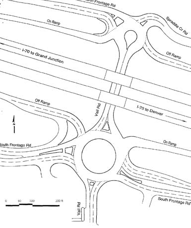
Source: National Cooperative Highway Research Program
Figure 200. Illustration. Raindrop interchange in Vail, CO.(98)
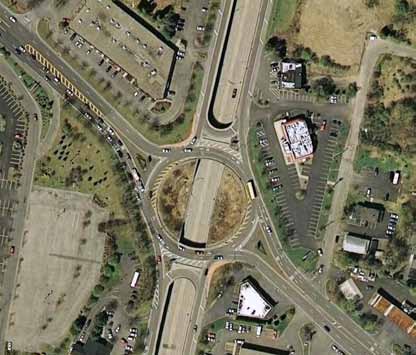
Source: Google™ Earth
Figure 201. Photo. Single roundabout interchange in Latham, NY.
There are several existing raindrop interchanges located in North Carolina, Colorado, Maryland, and Washington, DC.
9.3.2 MUT Interchange
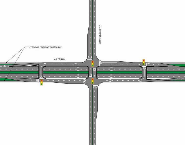
The MUT interchange, also known as the Michigan urban diamond interchange (MUDI), evolved in Michigan from the MUT intersection to be used on freeway facilities, as shown in figure 202.
The MUDI uses directional crossovers beyond the main intersection to handle all left-turn movements. The arterial turn movements are diverted onto separate frontage roads on either side of the grade-separated through lanes. Off-ramps are directed onto one-way frontage approximately 500 to 600 ft prior to the main intersection. At the main intersection, right turns are made. Left turns proceed to the directional crossover beyond the main intersection, and drivers must make a U-turn and then a right turn onto the cross street. The main intersection and the crossovers operate under a two-phase signal control and are coordinated to promote progression.(96)
Pedestrians cross the arterial with the help of a two-stage crossing. The MUDI is good from an access management point-of-view, and access to adjacent business development is possible along the parallel one-way frontage roads. This kind of interchange has been applied in Michigan along freeway corridors where right-of-way acquisition is an issue.
Source: ATTAP Maryland State Highway Administration
Figure 202. Illustration. MUT interchange configuration.(4)
Dorothy, et al. researched the operational aspects of the MUDI by performing computer traffic simulation runs using TRAF-NETSIM on geometrically similar MUDI and diamond interchanges models.(99) Simulation results indicated MUDI performed operationally better than the conventional diamond interchange for a majority of the cases.
9.3.3 Center Turn Overpass Interchange
The center turn overpass (CTO) interchange separates left-turn movements of all the approaches by relocating them to an elevated structure using narrow ramps within the median.(96) The arterial and cross street through and right-turn movements continue to use the roads at normal elevation. Both the elevated and at-grade intersections are controlled by a simple two-phase signal. The left-turn traffic descends from the elevated intersection and merges into through traffic lanes. The concept, which hase been conceived and patented, is shown in figure 203, and the typical movements are shown in figure 204. The elevated structure is usually on a retaining wall or a steel girder structure. In this kind of design, the traffic descending from the elevated structure requires a merging/deceleration lane to merge with the through traffic of the receiving approach. Alternatively, the signal on the elevated structure could be coordinated with the signal at the main intersection such that the descending traffic could merge when the through traffic in the same direction stopped.(96)
Source: ATTAP Maryland State Highway Administration
Figure 203. Illustration. CTO interchange configuration.(4)
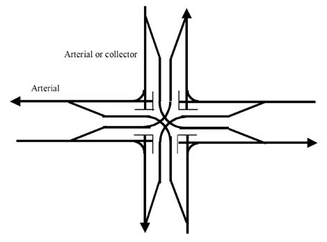
Figure 204. Illustration. Typical movements in a CTO interchange configuration.
Some of the advantages of a CTO interchange compared to a conventional at-grade intersection are as follows:(100)
- Higher capacity than at-grade intersections.
- Lower travel time than at-grade intersections.
- Enhanced progression for both streets.
- Metered traffic to help downstream signals.
- Direct pedestrian crossing.
- Roadside access to businesses similar to conventional intersection with medians.
Some of the disadvantages are as follows:
- High structure cost.
- Difficult design if streets are not perpendicular.
- Blocked visibility to businesses by structure.
- Costs for rights to design.
9.3.4 Echelon Interchange
For an echelon interchange, one approach on both the arterial and intersecting cross streets is structurally elevated as the cross streets intersect while the other approach halves on both the arterial and intersecting cross streets intersect at-grade as depicted in figure 205. Typical movements on an echelon interchange are shown in figure 206. The result is a symmetrical
but offset pair of two-phase intersections separated by grade, both operated by two-phase signals as in the meeting of two one-way streets. The elevation is provided with the help of retaining wall structures. With the elevation of two of the approaches, the intersections can be operated with two-phase signals. Figure 207 shows the only known application in Aventura, FL, at
U.S. Route 1 and NE 203 Street.(96)
Source: ATTAP Maryland State Highway Administration
Figure 205. Illustration. Typical echelon interchange configuration.(4)
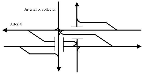
Figure 206. Illustration. Typical movements in an echelon interchange.(4)
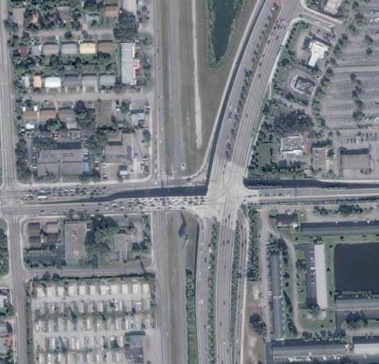
Source: Google™ Earth
Figure 207. Photo. Example of an echelon interchange in Aventura, FL.
Some of the advantages of an echelon interchange in comparison to a conventional intersection are as follows:(100)
- Higher capacity than at-grade intersections.
- Lower travel time than at-grade intersections.
- Enhanced progression for both streets.
- Metered traffic to help downstream signals.
Some of the disadvantages are as follows:(100)
- High structure cost.
- Impaired access to three quadrants.
- U-turn opportunities not available at or near interchange.
- Pedestrians cross grades or cross streets unprotected by signals.
Echelon interchanges are appropriate at high-volume urban or suburban intersections located within a signalized network where arterial and cross street volumes are similar.(96)
|


