Comprehensive Design Example for Prestressed Concrete (PSC) Girder Superstructure Bridge
Design Step 7 Design of Substructure
Design Step 7.1 - Integral Abutment Design
General considerations and common practices
Integral abutments are used to eliminate expansion joints at the end of a bridge. They often result in "Jointless Bridges" and serve to accomplish the following desirable objectives:
- Long-term serviceability of the structure
- Minimal maintenance requirements
- Economical construction
- Improved aesthetics and safety considerations
A jointless bridge concept is defined as any design procedure that attempts to achieve the goals listed above by eliminating as many expansion joints as possible. The ideal jointless bridge, for example, contains no expansion joints in the superstructure, substructure or deck.
Integral abutments are generally founded on one row of piles made of steel or concrete. The use of one row of piles reduces the stiffness of the abutment and allows the abutment to translate parallel to the longitudinal axis of the bridge. This permits the elimination of expansion joints and movable bearings. Because the earth pressure on the two end abutments is resisted by compression in the superstructure, the piles supporting the integral abutments, unlike the piles supporting conventional abutments, do not need to be designed to resist the earth loads on the abutments.
When expansion joints are completely eliminated from a bridge, thermal stresses must be relieved or accounted for in some manner. The integral abutment bridge concept is based on the assumption that due to the flexibility of the piles, thermal stresses are transferred to the substructure by way of a rigid connection, i.e. the uniform temperature change causes the abutment to translate without rotation. The concrete abutment contains sufficient bulk to be considered as a rigid mass. A positive connection to the girders is generally provided by encasing girder ends in the reinforced concrete backwall. This provides for full transfer of forces due to thermal movements and live load rotational displacement experienced by the abutment piles.
Design criteria
Neither the AASHTO-LRFD Specifications nor the AASHTO-Standard Specifications contain detailed design criteria for integral abutments. In the absence of universally-accepted design criteria, many states have developed their own design guidelines. These guidelines have evolved over time and rely heavily on past experience with integral abutments at a specific area. There are currently two distinctive approaches used to design integral abutments:
- One group of states design the piles of an integral abutment to resist only gravity loads applied to the abutment. No consideration is given to the effect of the horizontal displacement of the abutment on the pile loads and/or pile resistance. This approach is simple and has been used successfully. When the bridge is outside a certain range set by the state, e.g. long bridges, other considerations are taken into account in the design.
- The second approach accounts for effects of different loads, in additional to gravity loads, when calculating pile loads. It also takes into account the effect of the horizontal movements on the pile load resistance. One state that has detailed design procedures following this approach is Pennsylvania.
The following discussion does not follow the practices of a specific state; it provides a general overview of the current state-of-practice.
Bridge length limits
Most states set a limit on the bridge length of jointless bridges beyond which the bridge is not considered a "typical bridge" and more detailed analysis is taken into account. Typically, the bridge length is based on assuming that the total increase of the bridge length under uniform temperature change from the extreme low to the extreme high temperature is 4 inches. This means that the movement at the top of the pile at each end is 2 inches or, when the bridge is constructed at the median temperature, a 1 inch displacement in either direction. This results in a maximum bridge length of 600 ft. for concrete bridges and 400 ft. for steel bridges at locations where the climate is defined as "Moderate" in accordance to S3.12.2.1. The maximum length is shorter for regions defined as having a "cold" climate.
Soil conditions
The above length limits assume that the soil conditions at the bridge location and behind the abutment are such that the abutment may translate with relatively low soil resistance. Therefore, most jurisdictions specify select granular fill for use behind integral abutments. In addition, the fill within a few feet behind the integral abutment is typically lightly compacted using a vibratory plate compactor (jumping jack). When bedrock, stiff soil and/or boulders exist in the top layer of the soil (approximately the top 12 to 15 ft.), it is typically required that oversized holes be drilled to a depth of approximately 15 ft.; the piles are then installed in the oversized holes. Subsequently, the holes are filled with sand. This procedure is intended to allow the piles to translate with minimal resistance.
Skew angle
Earth pressure acts in a direction perpendicular to the abutments. For skewed bridges, the earth pressure forces on the two abutments produce a torque that causes the bridge to twist in plan. Limiting the skew angle reduces this effect. For skewed, continuous bridges, the twisting torque also results in additional forces acting on intermediate bents.
In addition, sharp skews are suspected to have caused cracking in some abutment backwalls due to rotation and thermal movements. This cracking may be reduced or eliminated by limiting the skew. Limiting the skew will also reduce or eliminate design uncertainties, backfill compaction difficulty and the additional design and details that would need to be worked out for the abutment U-wingwalls and approach slab.
Currently, there are no universally accepted limits on the degree of skew for integral abutment bridges.
Horizontal alignment and bridge plan geometry
With relatively few exceptions, integral abutments are typically used for straight bridges. For curved superstructures, the effect of the compression force resulting from the earth pressure on the abutment is a cause for concern. For bridges with variable width, the difference in the length of the abutments results in unbalanced earth pressure forces if the two abutments are to move the same distance. To maintain force equilibrium, it is expected that the shorter abutment will deflect more than the longer one. This difference should be considered when determining the actual expected movement of the two abutments as well as in the design of the piles and the expansion joints at the end of the approach slabs (if used).
Grade
Some jurisdictions impose a limit on the maximum vertical grade between abutments. These limits are intended to reduce the effect of the abutment earth pressure forces on the abutment vertical reactions.
Girder types, maximum depth and placement
Integral abutments have been used for bridges with steel I-beams, concrete I-beams, concrete bulb tees and concrete spread box beams.
Deeper abutments are subjected to larger earth pressure forces and, therefore, less flexible. Girder depth limits have been imposed by some jurisdictions based on past successful practices and are meant to ensure a reasonable level of abutment flexibility. Soil conditions and the length of the bridge should be considered when determining maximum depth limits. A maximum girder depth of 6 ft. has been used in the past. Deeper girders may be allowed when the soil conditions are favorable and the total length of the bridge is relatively short.
Type and orientation of piles
Integral abutments have been constructed using steel H-piles, concrete-filled steel pipe piles and reinforced and prestressed concrete piles. For H-piles, there is no commonly used orientation of the piles. In the past, H-piles have been placed both with their strong axis parallel to the girder's longitudinal axis and in the perpendicular direction. Both orientations provide satisfactory results.
Consideration of dynamic load allowance in pile design
Traditionally, dynamic load allowance is not considered in foundation design. However, for integral abutment piles, it may be argued that the dynamic load allowance should be considered in the design of the top portion of the pile. The rationale for this requirement is that the piles are almost attached to the superstructure, therefore, the top portions of the piles do no benefit from the damping effect of the soil.
Construction sequence
Typically, the connection between the girders and the integral abutment is made after the deck is poured. The end portion of the deck and the backwall of the abutment are usually poured at the same time. This sequence is intended to allow the dead load rotation of the girder ends to take place without transferring these rotations to the piles.
Two integral abutment construction sequences have been used in the past:
- One-stage construction:
In this construction sequence, two piles are placed adjacent to each girder, one pile on each side of the girder. A steel angle is connected to the two piles and the girder is seated on the steel angle. The abutment pier cap (the portion below the bottom of the beam) and the end diaphragm or backwall (the portion encasing the ends of the beams) are poured at the same time. The abutment is typically poured at the time the deck in the end span is poured.
- Two-stage construction:
Stage 1:
A pile cap supported on one row of vertical piles is constructed. The piles do not have to line up with the girders. The top of the pile cap reaches the bottom of the bearing pads under the girders. The top of the pile cap is required to be smooth in the area directly under the girders and a strip approximately 4 in. wide around this area. Other areas are typically roughened (i.e. rake finished).Stage 2:
After pouring the entire deck slab, except for the portions of the deck immediately adjacent to the integral abutment (approximately the end 4 ft. of the deck from the front face of the abutment) the end diaphragm (backwall) encasing the ends of the bridge girders is poured. The end portion of the deck is poured simultaneously with the end diaphragm.
Negative moment connection between the integral abutment and the superstructure
The rigid connection between the superstructure and the integral abutment results in the development of negative moments at this location. Some early integral abutments showed signs of deck cracking parallel to the integral abutments in the end section of the deck due to the lack of proper reinforcement to resist this moment. This cracking was prevented by specifying additional reinforcement connecting the deck to the back (fill) face of the abutment. This reinforcement may be designed to resist the maximum moment that may be transferred from the integral abutment to the superstructure. This moment is taken equal to the sum of the plastic moments of the integral abutment piles. The section depth used to design these bars may be taken equal to the girder depth plus the deck thickness. The length of the bars extending into the deck is typically specified by the bridge owner. This length is based on the length required for the superstructure dead load positive moment to overcome the connection negative moment.
Wingwalls
Typically, U-wingwalls (wingwalls parallel to the longitudinal axis of the bridge) are used in conjunction with integral abutments. A chamfer (typically 1 ft.) is used between the abutment and the wingwalls to minimize concrete shrinkage cracking caused by the abrupt change in thickness at the connection.
Approach slab
Bridges with integral abutments were constructed in the past with and without approach slabs. Typically, bridges without approach slabs are located on secondary roads that have asphalt pavements. Traffic and seasonal movements of the integral abutments cause the fill behind the abutment to shift and to self compact. This often caused settlement of the pavement directly adjacent to the abutment.
Providing a reinforced concrete approach slab tied to the bridge deck moves the expansion joint away from the end of the bridge. In addition, the approach slab bridges cover the area where the fill behind the abutment settles due to traffic compaction and movements of the abutment. It also prevents undermining of the abutments due to drainage at the bridge ends. Typically, approach slabs are cast on polyethylene sheets to minimize the friction under the approach slab when the abutment moves.
The approach slab typically rests on the abutment at one end and on a sleeper slab at the other. The approach slab differs from typical roadway pavement since the soil under the approach slab is more likely to settle unevenly resulting in the approach slab bridging a longer length than expected for roadway pavement. Typically, the soil support under the approach slab is ignored in the design and the approach slab is designed as a one-way slab bridging the length between the integral abutment and the sleeper slab. The required length of the approach slab depends on the total depth of the integral abutment. The sleeper slab should be placed outside the area where the soil is expected to be affected by the movement of the integral abutment. This distance is a function of the type of fill and the degree of compaction.
Due to the difference in stiffness between the superstructure and the approach slab, the interface between the integral abutment and the approach slab should preferably allow the approach slab to rotate freely at the end connected to the abutment. The reinforcement bars connecting the abutment to the approach slab should be placed such that the rotational restraint provided by these bars is minimized.
A contraction joint is placed at the interface between the approach slab and the integral abutment. The contraction joint at this location provides a controlled crack location rather than allowing a random crack pattern to develop.
Expansion joints
Typically, no expansion joints are provided at the interface between the approach slab and the roadway pavement when the bridge total length is relatively small and the roadway uses flexible pavement. For other cases, an expansion joint is typically used.
Bearing pads
Plain elastomeric bearing pads are placed under all girders when the integral abutment is constructed using the two-stage sequence described above. The bearing pads are intended to act as leveling pads and typically vary from ½ to ¾ in. thick. The pad length parallel to the girder's longitudinal axis varies depending on the bridge owner's specifications and the pad length in the perpendicular direction varies depending on the width of the girder bottom flange and the owner's specifications. It is recommended to block the area under the girders that is not in contact with the bearing pads using backer rods. Blocking this area is intended to prevent honeycombing of the surrounding concrete. Honeycombing will take place when the cement paste enters the gap between the bottom of girder and the top of the pile cap in the area under the girders not in contact with the bearing pads.
Design Step 7.1.1 - Gravity loads
Interior girder: unfactored loads
(See Table 5.3-3 for girder end shears)
Noncomposite: Girder = 61.6 k Slab and haunch = 62.2 k Exterior diaphragm = 2.5 k Total NC = 126.4 k
| Parapets | = 8.9 k |
| Future wearing surface | = 12.0 k |
Live load: Maximum truck per lane (without impact or distribution factors) = 64.42 k Minimum truck per lane (without impact or distribution factors) = -6.68 k Maximum lane per lane = 30.81 k Minimum lane per lane = -4.39 k
Exterior girder: unfactored loads
(See Table 5.3-7 for girder end shears)
Noncomposite: Girder = 61.6 k Slab and haunch = 55.1 k Exterior diaphragm = 1.3 k Total NC = 117.9 k
| Parapets | = 8.9 k |
| Future wearing surface | = 8.1 k |
| Maximum truck per lane (without impact or distribution factors) | = 64.42 k |
| Minimum truck per lane (without impact or distribution factors) | = -6.68 k |
| Maximum lane per lane | = 30.81 k |
| Minimum lane per lane | = -4.39 k |
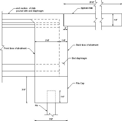
Figure 7.1-1 - General View of an Integral Abutment Showing Dimensions Used for the Example
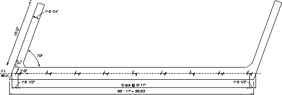
Figure 7.1-2 - Plan View of the Integral Abutment
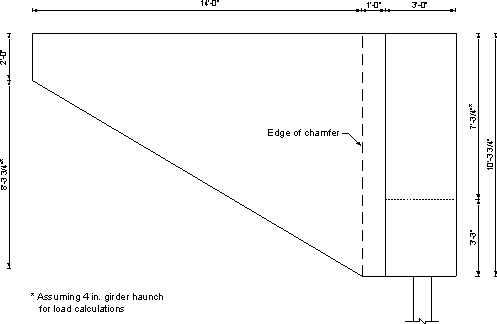
Figure 7.1-3 - Elevation View of Integral Abutment and Tapered Wingwall
In the next section, "w" and "P" denote the load per unit length and the total load, respectively. The subscripts denote the substructure component. Dimensions for each component are given in Figures 7.1-1 through 7.1-3.
Pile cap: unfactored loading
| Pile cap length along the skew | = 55.354/cos 20 = 58.93 ft. |
| wcap | = 3.25(3)(0.150) = 1.46 k/ft |
OR
| Pcap | = 1.46(58.93) = 86.0 k |
Concrete weight from the end diaphragm (approximate, girder volume not removed): unfactored loading
Assuming bearing pad thickness of ¾ in., girder height of 72 in., haunch thickness of 4 in., and deck thickness of 8 in.:
| wend dia | = 3[(0.75 + 72 + 4 + 8)/12](0.150) = 3.18 k/ft |
OR
| Pend dia | = 3.18(58.93) = 187.4 k |
Wingwall: unfactored load
| Awing | = (123.75/12)(15) - ½ (14)(99.75/12) = 96.5 ft2 |
| Wingwall thickness | = parapet thickness at the base = 20.25 in. (given in Section 4) |
| Wingwall weight | = 96.5(20.25/12)(0.150) = 24.43 k |
| Chamfer weight | = (123.75/12)(1.0)(1.0)(0.150)/2 = 0.77 k |
Notice that the chamfer weight is insignificant and is not equal for the two sides of the bridge due to the skew. For simplicity, it was calculated based on a right angle triangle and the same weight is used for both sides.
| Weight of two wingwalls plus chamfer | = 2(24.43 + 0.77) = 50.4 k |
| Parapet weight = 0.65 k/ft (given in Section 5.2) | |
| Parapet length on wingwall and abutment | = 15 + 3/ sin 70 = 18.19 ft. |
| Pparapet | = 2(0.650)(18.19) = 23.65 k total weight |
Approach slab load acting on the integral abutment: unfactored loading
Approach slab length = 25 ft.
| Approach slab width between parapets | = 58.93 - 2[(20.25/12)/sin 70] = 55.34 ft. |
Self weight of the approach slab:
| wapproach slab | = ½ (25)(1.5)(0.150) = 2.81 k/ft |
OR
| Papproach slab | = 2.81(55.34) = 155.5 k |
Future wearing surface acting on the approach slab (assuming 25 psf):
| wFWS | = ½ (0.025)(25) = 0.31 k/ft |
OR
| PFWS | = 0.31(55.34) = 17.2 k |
Live load on the approach slab, reaction on integral abutment:
| Plane load | = ½ (0.64)(25) (S3.6.1.2.4) = 8.0 k (one lane) |
Notice that one truck is allowed in each traffic lane and that the truck load is included in the girder reactions. Therefore, no trucks were assumed to exist on the approach slab and only the uniform load was considered.
Design Step 7.1.2 - Pile cap design
The girder reactions, interior and exterior, are required for the design of the abutment pile cap. Notice that neither the piles nor the abutment beam are infinitely rigid. Therefore, loads on the piles due to live loads are affected by the location of the live load across the width of the integral abutment. Moving the live load reaction across the integral abutment and trying to maximize the load on a specific pile by changing the number of loaded traffic lanes is not typically done when designing integral abutments. As a simplification, the live load is assumed to exist on all traffic lanes and is distributed equally to all girders in the bridge cross section. The sum of all dead and live loads on the abutment is then distributed equally to all piles supporting the abutment.
The maximum number of traffic lanes allowed on the bridge based on the available width (52 ft. between gutter lines) is:
| Nlanes | = 52 ft./12 ft. per lane = 4.33 say 4 lanes |
Factored dead load plus live load reactions for one interior girder, Strength I limit state controls (assume the abutment is poured in two stages as discussed earlier):
Maximum reaction Stage I:
| PSI(I) | = 1.25(girder + slab + haunch) = 1.25(126.4) = 158 k |
Notice that construction loads should be added to the above reaction if construction equipment is allowed on the bridge before pouring the backwall (Stage II).
Maximum reaction for Final Stage:
Including the dynamic load allowance (for design of the pile cap top portion of the piles):
PFNL(I) = 1.25(DC) + 1.50(DW) + 1.75(LL + IM)(Nlanes)/Ngirders
= 1.25(126.4 + 8.9) + 1.5(12.0) + 1.75[1.33(64.42) + 30.81](4)/6
= 323 kWithout the dynamic load allowance (for design of the lower portion of the piles):
PFNL(I) = 298.3 k
Factored dead load plus live load reactions for one exterior girder, Strength I limit state controls:
Maximum reaction Stage I:
| PSI(E) | = 1.25(117.9) = 147.4 k |
Notice that construction loads should be added to the above reaction.
Maximum reaction for Final Stage:
Including the dynamic load allowance:
PFNL(E) = 1.25(DC) + 1.50(DW) + 1.75(LL + IM)(Nlanes)/Ngirders
= 1.25(117.9 + 8.9) + 1.5(8.1) + 1.75[1.33(64.42) + 30.81](4)/6
= 306.6 kWithout the dynamic load allowance:
PFNL(E)= 281.8 k
Design Step 7.1.3 - Piles
Typically, integral abutments may be supported on end bearing piles or friction piles. Reinforced and prestressed concrete piles, concrete-filled steel pipe piles or steel H-piles may be used. Steel H-piles will be used in this example.
Typically, the minimum distance between the piles and the end of the abutment, measured along the skew, is taken as 1'-6" and the maximum distance is usually 2'-6". These distances may vary from one jurisdiction to another. The piles are assumed to be embedded 1'-6" into the abutment. Maximum pile spacing is assumed to be 10 ft. The minimum pile spacing requirements of S10.7.1.5 shall apply.
- From S10.7.1.5, the center-to-center pile spacing shall not be less than the greater of 30.0 in. or 2.5 pile diameters (or widths). The edge distance from the side of any pile to the nearest edge of the footing shall be greater than 9.0 in.
- According to S10.7.1.5, where a reinforced concrete beam is cast-in-place and used as a bent cap supported by piles, the concrete cover at the sides of the piles shall be greater than 6.0 in., plus an allowance for permissible pile misalignment, and the piles shall project at least 6.0 in. into the cap. This provision is specifically for bent caps, therefore, keep 1'-6" pile projection for integral abutment to allow the development of moments in the piles due to movements of the abutment without distressing the surrounding concrete.
From Figure 7.1-2, steel H-piles are shown to be driven with their weak axis perpendicular to the centerline of the beams. As discussed earlier, piles were also successfully driven with their strong axis perpendicular to the centerline of the beams in the past.
According to S10.7.4.1, the structural design of driven concrete, steel, and timber piles must be in accordance with the provisions of Sections S5, S6, and S8 respectively. Articles S5.7.4, S5.13.4, S6.15, S8.4.13, and S8.5.2.2 contain specific provisions for concrete, steel, and wood piles. Design of piles supporting axial load only requires an allowance for unintended eccentricity. For the steel H-piles used in this example, this has been accounted for by the resistance factors in S6.5.4.2 for steel piles.
General pile design
As indicated earlier, piles in this example are designed for gravity loads only.
Generally, the design of the piles is controlled by the minimum capacity as determined for the following cases:
- Case A - Capacity of the pile as a structural member according to the procedures outlined in S6.15. The design for combined moment and axial force will be based on an analysis that takes the effect of the soil into account.
- Case B - Capacity of the pile to transfer load to the ground.
- Case C - Capacity of the ground to support the load.
For piles on competent rock, only Case A needs to be investigated.
Design Step 7.1.3.1 - Pile compressive resistance (S6.15 and S6.9.2)
The factored resistance of components in compression, Pr, is taken as:
Pr = φPn (S6.9.2.1-1)
where:
Pn = nominal compressive resistance specified in S6.9.4 and S6.9.5 (kip) φc = resistance factor for axial compression, steel only as specified in S6.5.4.2
= 0.5 for H-piles assuming severe driving conditions
Check the width/thickness requirements per S6.9.4.2. Assume HP12x53 piles.
Slenderness of plates must satisfy:

where:
k = plate buckling coefficient as specified in Table S6.9.4.2-1 = 0.56 for flanges and projecting legs or plates b = width of plate equals one-half of flange width as specified in Table S6.9.4.2-1 (in.) = 12.045/2 = 6.02 in. t = flange thickness (in.) = 0.435 in.
= 13.8
= 15.9 > 13.8
Therefore, use S6.9.4.1 to calculate the compressive resistance.
(Notice that the b/t ratio for the webs of HP sections is always within the limits of Table S6.9.4.2-1 for webs and, therefore, need not be checked.)
For piles fully embedded in soil, the section is considered continuously braced and Eq. S6.9.4.1-1 is reduced to Pn = FyAs.
| Pn | = 36(15.5) = 558 k |
Therefore, the factored resistance of components in compression, Pr, is taken as:
| Pr | = φPn = 0.5(558) = 279 k |
The above capacity applies to the pile at its lower end where damage from driving may have taken place. At the top of the pile, higher resistance factors that do not account for damage may be used. For piles designed for gravity loads only, as in this example, the resistance at the lower end will always control due to the lower resistance factor regardless if the dynamic load allowance is considered in determining the load at the top of the pile or not (notice that the dynamic load allowance is not considered in determining the load at the bottom of the pile).
Design Step 7.1.3.2 - Determine the number of piles required
Maximum total girder reactions for Stage I (detailed calculations of girder reactions shown earlier):
| PSI (Total) | = 2(147.4) + 4(158) = 926.8 k |
Maximum total girder reaction for final stage not including the dynamic load allowance (detailed calculations of girder reactions shown earlier):
| PFNL(Total) | = 2(281.8) + 4(298.3) = 1,756.8 k |
Maximum factored DL + LL on the abutment, Strength I limit state controls:
| PStr. I | = PFNL(Total) + 1.25(DC) + 1.50(DW) + 1.75(LLmax)(Nlanes) = 1,756.8 + 1.25(86.0 + 187.4 + 50.4 + 23.65 + 155.5) + 1.5(17.2) + 1.75(8.0)(4) = 1,756.8 + 710.5 = 2,467 k |
where:
"PFNL(Total) " is the total factored DL + LL reaction of the bridge girders on the abutment.
"DC " includes the weight of the pile cap, diaphragm, wingwalls, approach slab and parapet on the wingwalls.
"DW " includes the weight of the future wearing surface on the approach slab.
"LLmax " is the live load reaction from the approach slab transferred to the abutment (per lane)
"Nlanes " is the maximum number of traffic lanes that fit on the approach slab, 4 lanes.
Therefore, the number of piles required to resist the applied dead and live loads is:
| Npiles | = PStr. I/Pr = 2,467/279 = 8.84 piles, say 9 piles |
Design Step 7.1.3.3 - Pile spacing
Total length of the pile cap = 58.93 ft.
Assume pile spacing is 6'-11 " (6.917 ft.) which provides more than the recommended edge distance of 1'-6 " for the piles.
Pile end distance = [58.93 -8(6.917)]/2
= 1.80 ft. (1'-9 ½ ")
Design Step 7.1.4 - Backwall design
The thickness of the abutment backwall is taken to be 3 ft.
Design of the pier cap for gravity loads
For an integral abutment constructed in two stages, the abutment is designed to resist gravity loads as follows:
- Case A - The first stage of the abutment, i.e., the part of the abutment below the bearing pads, is designed to resist the self weight of the abutment, including the diaphragm, plus the reaction of the girders due to the self weight of the girder plus the deck slab and haunch.
- Case B - The entire abutment beam, including the diaphragm, is designed under the effect of the full loads on the abutment.
Instead of analyzing the abutment beam as a continuous beam supported on rigid supports at pile locations, the following simplification is common in conducting these calculations and is used in this example:
- Calculate moments assuming the abutment beam acting as a simple span between piles and then taking 80% of the simple span moment to account for the continuity. The location of the girder reaction is often assumed at the midspan for moment calculations and near the end for shear calculations. This assumed position of the girders is meant to produce maximum possible load effects. Due to the relatively large dimensions of the pile cap, the required reinforcement is typically light even with this conservative simplification.
Required information:
Concrete compressive strength, f′c = 3 ksi
Reinforcing steel yield strength, Fy = 60 ksi
Pile spacing = 6.917 ft.
Case A
The maximum factored load due to the girders and slab (from the interior girder):
| Pu | = 1.5(126.4) = 189.6 k |
Factored load due to the self weight of the pile cap and diaphragm:
| wu | = 1.5(1.46 + 3.18) = 6.96 k/ft |
Notice that only dead loads exist at this stage. The 1.5 load factor in the above equations is for Strength III limit state, which does not include live loads.
Flexural design for Case A
The maximum positive moment, Mu, assuming a simple span girder, is at midspan between piles. The simple span moments are reduced by 20% to account for continuity:
| Mu | = Pul/4 + wul2/8 = 0.8[189.6(6.917)/4 + 6.96(6.917)2/8] = 295.6 k-ft |
Determine the required reinforcing at the bottom of the pile cap.
Mr = φMn (S5.7.3.2.1-1)
The nominal flexural resistance, Mn, is calculated using Eq. (S5.7.3.2.2-1).
Mn = Asfy(ds -a/2) (S5.7.3.2.2-1)where:
As = area of nonpresstressed tension reinforcement (in2), notice that available room will only allow four bars, two on either side of the piles. Use 4 #8 bars.
= 4(0.79)
= 3.16 in2fy = specified yield strength of reinforcing bars (ksi)
= 60 ksids = distance from the extreme compression fiber to the centroid of the nonprestressed tensile reinforcement (in.)
= depth of pile cap -bottom cover -½ diameter bar
= 3.25(12) -3 -½(1.0)
= 35.5 in.a = cβ1, depth of the equivalent stress block (in.) (S5.7.3.1.1-4)
= Asfy/0.85f′cb
= 3.16(60)/[0.85(3)(3.0)(12)]
= 2.07 in.
Mn = 3.16(60)(35.5 -2.07/2)/12
= 544.5 k-ft
Therefore,
| Mr | = 0.9(544.5) = 490 k-ft > Mu = 295.6 k-ft OK |
Negative moment over the piles is taken equal to the positive moment. Use the same reinforcement at the top of the pile cap as determined for the bottom (4 #8 bars).
By inspection:
- Mr > 4/3(Mu). This means the minimum reinforcement requirements of S5.7.3.3.2 are satisfied.
- The depth of the compression block is small relative to the section effective depth. This means that the maximum reinforcement requirements of S5.7.3.3.1 are satisfied.
Shear design for Case A
The maximum factored shear due to the construction loads assuming the simple span condition and girder reaction at the end of the span:
| Vu | = Pu + wul/2 = 189.6 + 6.96(6.917)/2 = 213.7 k |
The factored shear resistance, Vr, is calculated as:
Vr = φVn (S5.8.2.1-2)
The nominal shear resistance, Vn, is calculated according to S5.8.3.3 and is the lesser of:
Vn = Vc + Vs (S5.8.3.3-1)
OR
Vn = 0.25f′cbvdv (S5.8.3.3-2)where:
Vc β = factor indicating ability of diagonally cracked concrete to transmit tension as specified in S5.8.3.4
= 2.0f′c = specified compressive strength of the concrete (ksi)
= 3.0 ksibv = effective shear width taken as the minimum web width within the depth dv as determined in S5.8.2.9 (in.) dv = effective shear depth as determined in S5.8.2.9 (in.)
= 36 in.S5.8.2.9 states that dv is not to be taken less than the greater of 0.9de or 0.72h
dv = de -a/2
= 35.5-(2.07/2)
= 34.47 in.0.9de = 0.9(35.5)
= 31.95 in.0.72h = 0.72[3.25(12)]
= 28.08 in.
Therefore, dv should be taken as 34.47 in.
| Vc | = 135.8 k |
Assuming shear reinforcement is #5 @ 10 in. spacing perpendicular to the pier cap longitudinal axis.
Vs = Avfydv/s (S5.8.3.3-4)where:
Av = area of shear reinforcement within a distance "s " (in2)
= 2 legs(0.31)
= 0.62 in2s = spacing of stirrups (in.)
= 10 in.
Vs = 0.62(60)(34.47)/10
= 128.2 k
The nominal shear resistance, Vn, is taken as the smaller of:
Vn = 135.8 + 128.2= 264 k
OR
Vn = 0.25(3)(36)(34.47) = 930.7 k
Therefore, use the shear resistance due to the concrete and transverse steel reinforcement.
| Vr | = φVn = 0.9(264) = 237.6 k > Vu = 213.7 k OK |
Case B
The maximum factored load due to all applied dead and live loads which include the approach slab, live load on approach slab, etc. The load due to the wingwalls is not included since its load minimally affects the responses at the locations where girder reactions are applied.
Point load:
| PStr -I | = maximum factored girder reaction calculated earlier = 323 k |
Notice that the 323 k assumes that the live load is distributed equally to all girders. This approximation is acceptable since this load is assumed to be applied at the critical location for moment and shear. Alternately, the maximum reaction from the tables in Section 5.3 may be used.
Distributed load:
| wStr -I | = 1.25(cap self wt. + end diaph. + approach slab) + 1.5(approach FWS) + 1.75(approach slab lane load)(Nlanes)/Labutment = 1.25(1.46 + 3.18 + 2.81) + 1.5(0.31) + 1.75(8.0)(4)/58.93 = 10.73 k/ft |
Flexural design for Case B
The maximum positive moment is calculated assuming the girder reaction is applied at the midspan between piles and taking 80% of the simple span moment.
| Mu | = 0.8[323(6.917)/4 + 10.73(6.917)2/8] = 498.2 k-ft |
Determine the required reinforcing at the bottom of the pile cap.
Mr = φMn (S5.7.3.2.1-1)
and
Mn = Asfy(ds -a/2) (S5.7.3.2.2-1)
where:
As = use 4 #8 bars
= 4(0.79)
= 3.16 in2fy = 60 ksi ds = total depth of int. abut. (no haunch) -bottom cover -½ bar diameter
= 119.75 -3 -½(1.0)
= 116.25 in.a = Asfy/0.85f′cb (S5.7.3.1.1-4)
= 3.16(60)/[0.85(3)(3.0)(12)]
= 2.07 in.Mn = 3.16(60)(116.25 -2.07/2)/12
= 1,820 k-ft
Therefore,
| Mr | = 0.9(1,820) = 1,638 k-ft > Mu = 498.2 k-ft OK |
Negative moment over the piles is taken equal to the positive moment. Use the same reinforcement at the top of the abutment beam as determined for the bottom (4 #8 bars).
By inspection:
- Mr > 4/3(Mu).
- The depth of the compression block is small relative to the section effective depth.
Shear design for Case B
Assume the girder reaction is adjacent to the pile.
The maximum factored shear due to all applied loading:
| Vu | = Pu + wul/2 = 323 + 10.73(6.917)/2 = 360.1 k |
The factored shear resistance, Vr, is calculated as:
Vr = φVn (S5.8.2.1-2)
The nominal shear resistance, Vn, is calculated according to S5.8.3.3 and is the lesser of:
Vn = Vc + Vs (S5.8.3.3-1)
OR
Vn = 0.25f′cbvdv (S5.8.3.3-2)where:
Vc β = 2.0 f′c = 3.0 ksi bv = 36 in. dv = de -a/2 de = 116.25 in. (calculated earlier) dv = 116.25 -(2.07/2)
= 115.2 in.0.9de = 0.9(116.25)
= 104.6 in.0.72h = 0.72(119.75)
= 86.22 in.
Therefore, dv should be taken as 115.2 in.
The nominal shear resistance, Vn, is taken as the lesser of:
| Vc | = = 454.0 k |
Notice that Vc is large enough, relative to the applied load, that the contribution of the transverse shear reinforcement, Vs, is not needed.
OR
| Vn | = 0.25(3)(36)(115.2) = 3,110.4 k |
Therefore, use the shear resistance due to the concrete, Vc
| Vr | = φVn = 0.9(454.0) = 408.6 k > Vu = 360.1 k OK |
Typical reinforcement details of the abutment beam are shown in Figures 7.1-4 through 7.1-7. Notice that bar shapes vary depending on the presence of girders and/or piles at the section.
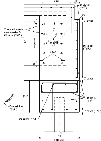
Figure 7.1-4 -Integral Abutment Reinforcement, Girder and Pile Exist at the Same Section
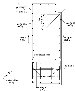
Figure 7.1-5 -Integral Abutment Reinforcement, No Girder and No Pile at the Section
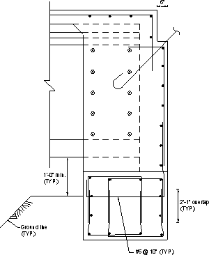
Figure 7.1-6 -Integral Abutment Reinforcement, Girder, No Pile at the Section
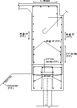
Figure 7.1-7 -Integral Abutment Reinforcement, Pile Without Girder
Design Step 7.1.4.1 - Design the backwall as a horizontal beam resisting passive earth pressure
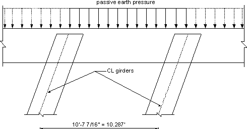
Figure 7.1-8 -Passive Earth Pressure Applied to Backwall
Calculate the adequacy of the backwall to resist passive pressure due to the abutment backfill material.
Passive earth pressure coefficient, kp = (1 + sin Φ)/(1 -sin Φ)
(Notice that kp may also be obtained from Figure S3.11.5.4-1)
wp = ½ γz2kp (S3.11.5.1-1)
where:
wp = passive earth pressure per unit length of backwall (k/ft) γ = unit weight of soil bearing on the backwall (kcf)
= 0.130 kcfz = height of the backwall from the bottom of the approach slab to the bottom of the pile cap (ft.)
= slab + haunch + girder depth + bearing pad thickness + pile cap depth -approach slab thickness
= (8/12) + (4/12) + 6 + (0.75/12) + 3.25 -1.5
= 8.81 ft.Φ = internal friction of backfill soil assumed to be 30°
wp = ½ (0.130)(8.81)2[(1 + sin 30)/(1 -sin 30)]
= 15.1 k/ft of wall
Notice that developing full passive earth pressure requires relatively large displacement of the structure (0.01 to 0.04 of the height of the structure for cohesionless fill). The expected displacement of the abutment is typically less than that required to develop full passive pressure. However, these calculations are typically not critical since using full passive pressure is not expected to place high demand on the structure or cause congestion of reinforcement.
No load factor for passive earth pressure is specified in the LRFD specifications. Assume the load factor is equal to that of the active earth pressure (φ = 1.5).
| wu | = φEHwp = 1.5(15.1) = 22.65 k/ft of wall |
The backwall acts as a continuous horizontal beam supported on the girders, i.e., with spans equal to the girder spacing along the skew.
| Mu | ≈ wul2/8 = 22.65(9.667/cos 20)2/8 = 300 k-ft/ft |
Calculate the nominal flexural resistance, Mr, of the backwall.
Mr = φMn (S5.7.3.2.1-1)
and
Mn = Asfy(ds -a/2) (S5.7.3.2.2-1)where:
As = area of the longitudinal reinforcement bars at front face (tension side) of the abutment (9 #6 bars)
= 9(0.44)
= 3.96 in2fy = 60 ksi ds = width of backwall -concrete cover -vertical bar dia. -½ bar dia.
= 3.0(12) -3 -0.625 -½ (0.75)
= 32.0 in.a = Asfy/0.85f′cb (S5.7.3.1.1-4)
where "b " is the height of the component
= 3.96(60)/[0.85(3)(119.75)]
= 0.78 in.
Mn = 3.96(60)(32.0 -0.78/2)/12
= 626 k-ft/ft
Therefore, the factored flexural resistance, where φ = 0.9 for flexure (S5.5.4.2.1), is taken as:
| Mr | = 0.9(626) = 563 k-ft/ft > Mu = 300 k-ft/ft OK |
By inspection:
Mr > 4/3(Mu).
The depth of the compression block is small relative to the depth.
Check shear for the section of backwall between girders:
| Vu | = Pul/2 = 22.65(9.667/sin 20)/2 = 116.5 k/ft |
The factored shear resistance, Vr, is calculated as:
Vr = φVn (S5.8.2.1-2)
The nominal shear resistance, Vn, is calculated according to S5.8.3.3 and is the lesser of:
Vn = Vc + Vs (S5.8.3.3-1)
OR
Vn = 0.25f′cbvdv (S5.8.3.3-2)where:
Vc β = 2.0 f′c = 3.0 ksi bv = effective horizontal beam width taken as the abutment depth (in.)
= 119.75 in.dv = de -a/2
= 32.0 -(0.78/2)
= 31.61 in.0.9de = 0.9(32.0)
= 28.8 in.0.72h = 0.72(36)
= 25.92 in.
Therefore, dv should be taken as 31.61 in.
Ignore the contribution of the transverse reinforcement to the shear resistance (i.e., Vs = 0), Vn is taken as the smaller of:
| Vc | = = 414.4 k/ft |
OR
| Vn | = 0.25(3)(119.75)(31.61) = 2,839 k/ft |
Therefore, use the shear resistance due to the concrete, Vc
| Vr | = φVn = 0.9(414.4) = 373.0 k/ft > Vu = 116.5 k/ft OK |
Design Step 7.1.5 - Wingwall design
There is no widely accepted method of determining design loads for the wingwalls of integral abutments. The following design procedure will result in a conservative design as it takes into account maximum possible loads.
Two load cases are considered:
Load Case 1:The wingwall is subjected to passive earth pressure. This case accounts for the possibility of the bridge moving laterally and pushing the wingwall against the fill. It is not likely that the displacement will be sufficient to develop full passive pressure. However, there is no available method to determine the expected pressure with certainty. This load case is considered under strength limit state.
Load Case 2:
The wingwall is subjected to active pressure and collision load on the parapet. Active pressure was considered instead of passive to account for the low probability that a collision load and passive pressure will exist simultaneously. This load case is considered at the extreme event limit state, i.e. φ = 1.0 (Table S3.4.1-1)
Required information:
| Angle of internal friction of fill, Φ | = 30 degrees |
| Coefficient of active earth pressure, ka | = (1 -sin Φ)/(1 + sin Φ) = 0.333 |
| Coefficient of passive earth pressure, kp | = (1 + sin Φ)/(1 -sin Φ) = 3 |
| ka/kp | = 0.333/3 = 0.111 |
Load Case 1
From Figure 7.1-9 and utilizing properties of a right angle pyramid [volume = 1/3(base area)(height) and the center of gravity (applied at a distance measured from the vertical leg of the right angle pyramid) = ¼ base length].
Moment at the critical section for moment under passive pressure:
| Mp | = 0.2(14)(0.5)(14/2) + 0.2[14(8.31/2)](14/3) + (1/3)[3.24(8.31)(14/2)](14/4) = 284 k-ft |
Minimum required factored flexural resistance, Mr = 284 k-ft.
Mr = φMn (S5.7.3.2.1-1)where:
Mn = nominal resistance (k-ft)
= Mpφ = 0.9 for flexure at the strength limit state (S5.5.4.2)
Min. required Mn = 284/0.9
= 316 k-ft
Load Case 2
Moment on the critical section for moment under active pressure:
| Ma | = 0.111(284) = 31.5 k-ft |
Moment from collision load on the parapet:
From SA13.2 for Test Level 5, the crash load on the parapet is equal to 124 kips and is applied over a length of 8 ft.
Maximum collision moment on the critical section:
| M | = 124(14 -8/2) = 1,240 k-ft |
| Total moment for Load Case 2, Mtotal | = 1,240 + 31.5 = 1,271.5 k-ft |
The minimum required factored flexural resistance, Mr = 1,271.5 k-ft
Mr = φMn (S5.7.3.2.1-1)where:
φ = 1.0 for flexure at the extreme event limit state Min. required Mn = 1,271.5/1.0
= 1,271.5 k-ft
From the two cases of loading:
Mn required = 1,271.5 k-ft
Develop a section that provides the minimum nominal flexural resistance
Required information:
Assuming reinforcement of #8 @ 6 in.
Number of bars within the 10.3125 ft. height of the wing wall = 22 bars
| Section thickness | = parapet thickness at base = 20.25 in. |
Concrete cover = 3 in.
The nominal flexural resistance, Mn, is taken as:
Mn = Asfy(ds -a/2) (S5.7.3.2.2-1)where:
ds = section thickness -cover -½ bar diameter
= 20.25 -3 -½(1.0)
= 16.75 in.As = 22(0.79)
= 17.38 in2a = Asfy/0.85f′cb (S5.7.3.1.1-4)
= 17.38(60)/[0.85(3)(123.75)]
= 3.30 in.
Mn = Asfy(ds -a/2)
= 17.38(60)(16.75 -3.30/2)/12
= 1,312 k-ft > 1,271.5 k-ft required OK
Secondary reinforcement of the wingwall is not by design, it is only meant for shrinkage. Use #6 @ 12 in. spacing as shown in Figure 7.1-10.
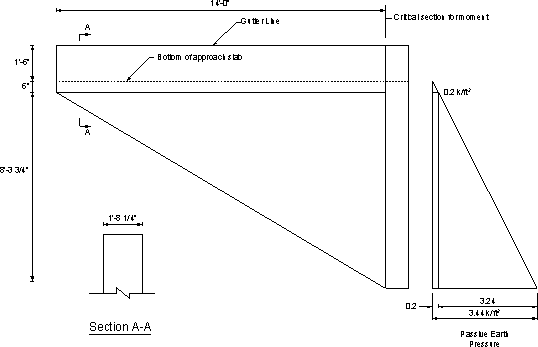
Figure 7.1-9 -Wingwall Dimensions
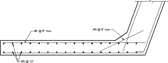
Figure 7.1-10 -Wingwall Reinforcement
Design Step 7.1.6 - Design of approach slab
Approach slab loading for a 1 ft. wide strip:
wself = 0.15(1.5) = 0.225 k/ft
wFWS = 0.025 k/ft
Factored distributed dead loading:
wStr I = 1.25(0.225) + 1.50(0.025) = 0.32 k/ft
Live load distribution width (S4.6.2.3)
The equivalent strip width of longitudinal strips per lane for both shear and moment is calculated according to the provisions of S4.6.2.3.
- For single lane loaded

- For multiple lanes loaded

where:
E = equivalent width (in.)
L1 = modified span length taken equal to the lesser of the actual span or 60.0 ft. (ft.)
W1 = modified edge-to-edge width of bridge taken to be equal to the lesser of the actual width or 60.0 ft. for multilane lading, or 30.0 ft. for single-lane loading (ft.)
W = physical edge-to-edge width of bridge (ft.)
NL = number of design lanes as specified in S3.6.1.1.1
Therefore, the equivalent strip width is:
E = 137.6 in.
Live load maximum moment:
Lane load: max moment = 0.64(25)2/8 = 50 k-ft
Truck load: max moment = 207.4 k-ft (from live load analysis output for a 25 ft. simple span)
Total LL + IM = 50 + 1.33(207.4) = 325.8 k-ft
Total LL + IM moment per unit width of slab = 325.8/(137.6/12) = 28.4 k-ft/ft
Maximum factored positive moment per unit width of slab due to dead load plus live load:
Mu = wl2/8 + 1.75(LL + IM moment) = 0.32(25)2/8 + 1.75(28.4) = 74.7 k-ft
The factored flexural resistance, Mr, is taken as:
| Mr | = φMn (S5.7.3.2.1-1) |
and
| Mn | = Asfy(d -a/2) (S5.7.3.2.2-1) |
||||||||
where:
| |||||||||
| Mn | = 1.33(60)(14.4 -2.61/2)/12 = 87.1 k-ft | ||||||||
Therefore,
| Mr | = 0.9(87.1) = 78.4 k-ft > Mu = 74.7 k-ft OK |
Design Step 7.1.6.1 - Bottom distribution reinforcement (S9.7.3.2)
For main reinforcement parallel to traffic, the minimum distribution reinforcement is taken as a percentage of the main reinforcement:
where:
S = the effective span length taken as equal to the effective length specified in S9.7.2.3 (ft.)
Assuming "S" is equal to the approach slab length,
Main reinforcement: #9 @ 9 in. = 1.0(12/9) = 1.33 in2/ft
Required distribution reinforcement = 0.2(1.33) = 0.27 in2/ft
Use #6 @ 12 in. = 0.44 in2/ft > required reinforcement OK
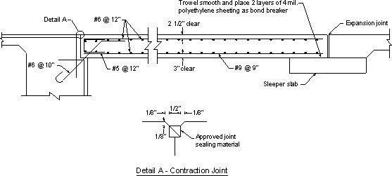
Figure 7.1-11 -Typical Approach Slab Reinforcement Details
Design Step 7.1.7 - Sleeper slab
No design provisions are available for sleeper slabs. The reinforcement is typically shown as a standard detail. If desired, moment in the sleeper slab may be determined assuming the wheel load is applied at the midpoint of a length assumed to bridge over settled fill, say a 5 ft. span length.
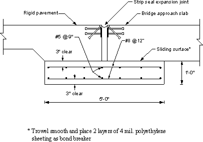
Figure 7.1-12 -Sleeper Slab Details Used by the Pennsylvania Department of Transportation

