

Appendix C - Calculations of Creep and Shrinkage Effects
See Design Step 5.3 for the basic information about creep and shrinkage effects. Design Step 5.3 also contains the table of fixed end moments used in this appendix.
Design Step C1.1 - Analysis of creep effects on the example bridge
Calculations are shown for Span 1 for a deck slab cast 450 days after the beams are made. Span 2 calculations are similar. See the tables at the end of this appendix for the final results for a case of the slab and continuity connection cast 30 days after the beams are cast. All calculations are made following the procedures outlined in the publication entitled "Design of Continuous Highway Bridges with Precast, Prestressed Concrete Girders" published by the Portland Cement Association (PCA) in August 1969.
The distance from the composite neutral axis to the bottom of the beam is 51.54 in. from Section 2. Therefore, the prestressing force eccentricity at midspan is:
ec = NAbottom-CGS = 51.54-5.0 = 46.54 in.
Design Step C1.2 Calculate the creep coefficient, ψ(t, ti), for the beam at infinite time according to S5.4.2.3.2.
Calculate the concrete strength factor, kf
kf = 1/[0.67 + (f′c/9)] = 1/[0.67 + (6.0/9)] = 0.748 (S5.4.2.3.2-2)
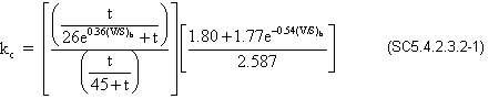
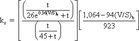
Calculate the volume to surface area factor, kc
where:
t = maturity of concrete = infinite days
e = natural log base (approx. 2.71828)
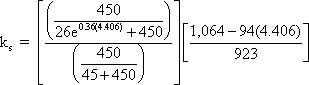
(V/S)b = volume to surface ratio for the beam = beam surface area is 2,955.38 in2/ft (see Figure 2-3 for beam dimensions) and the volume is 13,020 in3/ft = (13,020/2,955.38) = 4.406 in.
kc = 0.759
The creep coefficient is the ratio between creep strain and the strain due to permanent stress (SC5.4.2.3.2)
Calculate creep coefficient according to Eq. S5.4.2.3.2-1.
ψ(∞,1) = 3.5kckf(1.58-H/120)ti-0.118[(t-ti)0.6/(10.0 + (t-ti)0.6]
where:
kc = 0.759 (see above)
kf = 0.748 (see above)
H = relative humidity = 70%
ti = age of concrete when load is initially applied = 1 day
t = infinite daysψ(∞,1) = 3.5(0.759)(0.748)(1.58-70/120)(1)(-0.118)[1] = 1.98
Design Step C1.3 Calculate the creep coefficient, ψ(t,ti), in the beam at the time the slab is cast according to S5.4.2.3.2.
t = 450 days (maximum time)
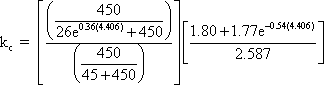
Calculate the volume to surface area factor, kc
where:
t = 450 days
e = natural log base (approx. 2.71828)
(V/S)b= 4.406 in.
kc = 0.651
Calculate the creep coefficient, ψ(t,ti), according to Eq. S5.4.2.3.2-1.
ψ(450,1) = 3.5kckf(1.58-H/120)ti-0.118[(t-ti)0.6/[10.0 + (t-ti)0.6]]
where:
kc = 0.651 (see above)
kf = 0.748 (see above)
H = 70%
ti = 1 day
t = 450 daysψ(450,1) = 3.5(0.651)(0.748)(1.58-70/120)(1)(-0.118)[(450-1)0.6/[10 + (450-1)0.6]] = 1.35
Calculate the restrained creep coefficient in the beam, Φ, as the creep coefficient for creep that takes place after the continuity connection has been established.
Φ = ψ∞- ψ450(from PCA publication referenced in Step 5.3.2.2) = 1.98-1.35 = 0.63
Design Step C1.4 - Calculate the prestressed end slope, θ.
For straight strands (debonding neglected). Calculate the end slope, θ, for a simple beam under constant moment.
Moment = Pec
θ = PecLspan/2EcIc
where:
P = initial prestressing force after all losses (kips) = 1,096 kips (see Design Step 5.4 for detailed calculations of the prestressing force)
ec = 46.54 in. (calculated above)
Lspan = 110.5 ft. (1,326 in.) (taken equal to the continuous beam span length)
Ec= the modulus of elasticity of the beam at final condition (ksi)
Ec = 4,696 ksi
Ic = moment of inertia of composite beam (in4) = 1,384,254 in4θ = [1,096(46.54)(1,326)]/[2(4,696)(1,384,254)] = 0.0052 rads
Design Step C1.5 - Calculate the prestressed creep fixed end action for Span 1
The equation is taken from Table 5.3-9 for prestressed creep FEA, left end span, right moment.
FEMcr = 3EcIcθ/Lspan
FEMcr = [3(4,696)(1,384,254)(0.0052)]/1,326
FEMcr = 76,476/12
FEMcr = 6,373 k-ft
End forces due to prestress creep in Span 1:
Left reaction = R1PScr
Left reaction = FEMcr/Lspan
Left reaction = (6,373)/110.5
Left reaction = 57.7 kRight reaction = R2PScr
Right reaction = -R1PScr
Right reaction = -57.7 kLeft moment = M1PScr
Left moment = 0.0 k-ftRight moment = M2PScr
Right moment = FEMcr
Right moment = 6,373 k-ft
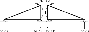
Figure C1-Presstress Creep Restraint Moment
Design Step C1.6 - Calculate dead load creep fixed end actions
Calculate the total dead load moment at the midspan
Noncomposite DL moment = MDN
Noncomposite DL moment = 42,144 k-in (3,512 k-ft) (see Section 5.3)Composite DL moment = MDC
Composite DL moment = 4,644 k-in (387 k-ft) (see Section 5.3)Total DL moment = MDL
Total DL moment = MDNC + MDC
Total DL moment = 42,144 + 4,644
Total DL moment = 46,788/12
Total DL moment = 3,899 k-ft
End forces due to dead load creep in Span 1:
Left reaction = R1DLcr
Left reaction = -MDL/Lspan
Left reaction = -3,899/110.5
Left reaction = -35.3 kRight reaction = R2DLcr
Right reaction = -R1DLcr
Right reaction = 35.3 kLeft moment = M1DLcr
Left moment = 0.0 k-ftRight moment = M2DLcr
Right moment = -MDL
Right moment = -3,899 k-ft
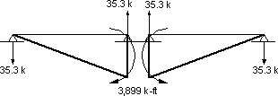
Figure C2-Dead Load Creep Restraint Moment
Calculate the creep correction factor, Ccr
Ccr = 1-e-Φ (from PCA publication referenced in Step 5.3.2.2) = 1-e-0.63= 0.467
Calculate the total creep (prestress + dead load) fixed end actions for 450 days.
Left reaction = R1cr
Left reaction = Ccr(R1PScr + R2DLcr)
Left reaction = 0.467(57.7 - 35.4)
Left reaction = 10.41 kRight reaction = R2cr
Right reaction = -R1cr
Right reaction = -10.41 kLeft moment = M1cr
Left moment = 0.0 k-ftRight moment = M2cr
Right moment = Ccr(M2PScr + M2DLcr)
Right moment = 0.467[6,373 + (-3,899)]
Right moment = 1,155 k-ft
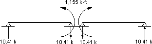
Figure C3-Total Creep Fixed End Actions
Design Step C1.7 - Creep final effects
The fixed end moments shown in Figure C3 are applied to the continuous beam. The beam is analyzed to determine the final creep effects. Due to the symmetry of the two spans of the bridge, the final moments at the middle support are the same as the applied fixed end moments. For a bridge with more than two spans or a bridge with two unequal spans, the magnitude of the final moments would be different from the fixed end moments.
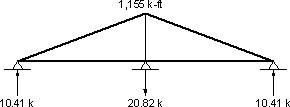
Figure C4-Creep Final Effects for a Deck and Continuity Connection Cast 450 Days After the Beams were Cast
Design Step C2.1 - Analysis of shrinkage effects on the example bridge
Calculate shrinkage strain in beam at infinite time according to S5.4.2.3.3
Calculate the size factor, ks.
where:
t = drying time = infinite days
e = natural log base (approx. 2.71828)
(V/S)b = 4.406 in.
![]()
ks = 0.704
Calculate the humidity factor, kh
Use Table S5.4.2.3.3-1 to determine kh for 70% humidity, kh = 1.0.
Assume the beam will be steam cured and devoid of shrinkage-prone aggregates, therefore, the shrinkage strain in the beam at infinite time is calculated as:
εsh,b,∞ = -kskh[t/(55.0 + t)](0.56 x 10-3) (S5.4.2.3.3-2)
where:
ks = 0.704
kh = 1.0 for 70% humidity (Table S5.4.2.3.3-1)
t = infinite daysεsh,b,∞ = -(0.704)(1.0)[1](0.56 x 10-3) = -3.94 x 10⁻⁴
Design Step C2.2 - Calculate shrinkage strain in the beam at the time the slab is cast (S5.4.2.3.3)
t = time the slab is cast = 450 days (maximum value)
Calculate the size factor, ks.
Ks =
where:
t = 450 days
e = natural log base (approx. 2.71828)
(V/S)b = 4.406 in.
ks = 0.604

Assume the beam will be steam cured and devoid of shrinkage-prone aggregates, therefore, the shrinkage strain in the beam at infinite time is calculated as:
εsh,b,450 = -kskh[t/(55.0 + t)](0.56 x 10-3) (S5.4.2.3.3-2)
where:
ks = 0.604
kh = 1.0 for 70% humidity (Table S5.4.2.3.3-1)
t = 450 daysεsh,b,450 = -(0.604)(1.0)[450/(55.0 + 450)](0.56 x 10-3) = -3.01 x 10⁻⁴
Design Step C2.3 - Calculate the shrinkage strain in the slab at infinite time (S5.4.2.3.3)
Calculate the size factor, ks
where:
t = infinite days
e = natural log base (2.71828)
Compute the volume to surface area ratio for the slab.
(V/S)s = (bslab)(tslab)/(2bslab-wtf)
where:
bslab = slab width taken equal to girder spacing (in.)
tslab = slab structural thickness (in.)
wtf = beam top flange width (in.)
(V/S)s = 116(7.5)/[2(116)-42] = 4.58 in.
ks = 0.686
The slab willnot be steam cured, therefore, use
εsh,s,∞ = -kskh[t/(35.0 + t)](0.51 x 10-3) (S5.4.2.3.3-1)
where:
ks = 0.686
kh = 1.0 for 70% humidity (Table S5.4.2.3.3-1)
t = infinite daysεsh,s,∞ = -(0.686)(1.0)[1.0](0.51 x 10-3) = -3.50 x 10⁻⁴
Design Step C2.4
Calculate the differential shrinkage strain as the difference between the deck total shrinkage strain and the shrinkage strain of the beam due to shrinkage that takes place after the continuity connection is cast.
Δεsh = εsh,s,∞ - (εsh,b,∞ - εsh,b,450)
Δεsh = -3.50 x 10⁻⁴-[-3.94 x 10⁻⁴-(-3.01 x 10⁻⁴)]
Δεsh = -2.57 x 10⁻⁴
Design Step C2.5 - Calculate the shrinkage driving end moment, Ms
Ms = ΔεshEcsAslabe′ (from PCA publication referenced in Design Step 5.3.2.2)
where:
Δεsh= differential shrinkage strain
Ecs = elastic modulus for the deck slab concrete (ksi)
Aslab = cross-sectional area of the deck slab (in2)
e′ = the distance from the centroid of the slab to the centroid of the composite section (in.)
e′ = dbeam + tslab/2-NAbeam bottom
e′ = 72 + 7.5/2-51.54 = 24.21 in.Ms = (-2.57 x 10⁻⁴)(3,834)(116)(7.5)(24.21)
Ms = 20,754/12
Ms = 1,730 k-ft (see notation in Table 5.3-9 for sign convention)
![]()
Figure C5-Shrinkage Driving Moment
For beams under constant moment along their full length, the restraint moment may be calculated as shown above for the case of creep due to prestressing force or according to Table 5.3-9.
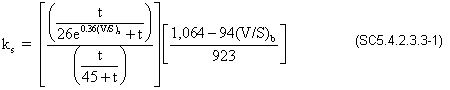
Shrinkage fixed end actions = -1.5Ms
Shrinkage fixed end actions = -1.5(1,730)
Shrinkage fixed end actions = -2,595 k-ft
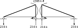
Figure C6-Shrinkage Fixed End Actions
Design Step C2.6 - Analyze the beam for the fixed end actions
Due to symmetry of the spans, the moments under the fixed end moments shown in Figure C6 are the same as the final moments (shown in Fig. C7). For bridges with three or more spans and for bridges with two unequal spans, the continuity moments will be different from the fixed end moments.
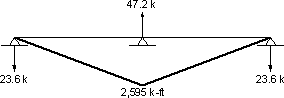
Figure C7-Shrinkage Continuity Moments
Design Step C2.7 Calculate the correction factor for shrinkage.
Csh = (1-e-Φ)/Φ (from PCA publication referenced in Step 5.3.2.2)
Csh = [1-e-0.63]/0.63
Csh = 0.742
Design Step C2.8
Calculate the shrinkage final moments by applying the correction factor for shrinkage to the sum of the shrinkage driving moments (Figure C5) and the shrinkage continuity moment (Figure C7) fixed end actions.
End moments, Span 1:
Left end moment = M1sh
Left end moment = Csh(Msh,dr + shrinkage continuity moment)
Left end moment = 0.742(1,730 + 0)
Left end moment = 1,284 k-ftRight end moment = M2sh
Right end moment = Csh(Msh,dr + shrinkage continuity moment)
Right end moment = 0.742(1,730-2,595)
Right end moment = -642 k-ft
Figure C8-Final Total Shrinkage Effect
Tables C1 and C2 provide a summary of the final moments for the case of the deck poured 30 days after the beams were cast.
Table C1 - 30 Day Creep Final Moments
| Span | M1 (k-ft) |
M2 (k-ft) |
R1 (k) |
R2 (k) |
|---|---|---|---|---|
| 1 | 0 | 1,962 | 17.7 | -17.7 |
| 2 | 1,962 | 0 | -17.7 | 17.7 |
Table C2 - 30 Day Shrinkage Final Moments
| Span | M1 (k-ft) |
M2 (k-ft) |
R1 (k) |
R2 (k) |
|---|---|---|---|---|
| 1 | 75.9 | -37.9 | -1.035 | 1.035 |
| 2 | -37.9 | 75.9 | 1.035 | -1.035 |
When a limit state calls for inclusion of the creep and shrinkage effects and/or the design procedures approved by the bridge owner calls for their inclusion, the final creep and shrinkage effects should be added to other load effect at all sections. The positive moment connection at the bottom of the beams at the intermediate support is designed to account for the creep and shrinkage effects since these effects are the major source of these moments.
Notice that when combining creep and shrinkage effects, both effects have to be calculated using the same age of beam at the time the continuity connection is established.