

U.S. Department of Transportation Federal Highway Administration |
MEMORANDUM |
| Subject: | ACTION: Hoan Bridge Investigation | Date: | July 10, 2001 |
| From: | /s/ Original signed by: James D. Cooper Director, Bridge Technology |
Reply to Attn. of: | HIBT-10 |
| To: | Directors of Field Services Division Administrators Federal Lands Highway Division Engineers |
||
This memorandum presents the latest findings from the forensic investigation into the cause of failure of the Hoan Bridge in Milwaukee, Wisconsin. In a memorandum dated February 1, I requested a review of the bridge inventory to identify structures that have design features similar to the Hoan. Responses indicate that at least 41 States and the District of Columbia have bridges with similar design characteristics as the Hoan. It is now encouraged that you work with your States to evaluate these bridges that have been identified as having similar details to the Hoan Bridge given the new information provided in the attachments. These structures should be assessed in further detail on a case-by-case basis to determine if the similar details might be subject to the same vulnerability as the Hoan.
The primary failure investigation was performed jointly between FHWA's Office of Infrastructure R&D, Lehigh University, and Lichtenstein Consulting Engineers, with the full cooperation and assistance of the Wisconsin DOT. Northwestern University and the University of Michigan also assisted in parts of the investigation. A final report on this investigation has been submitted to the Wisconsin DOT and copies will be forwarded to each Division Office for distribution to the States and to each Resource Center and Federal Lands Highway Office. Attached is a brief summary of the findings and the conclusions of the investigation team (Attachment A).
The team concluded that the primary cause of failure of the Hoan Bridge is the joint detail used to connect the lateral bracing system to the main girder webs. Some specific details of the joint created a condition that reduced the fracture resistance and made it vulnerable to premature failure. Research is indicating that this vulnerability is not an inherent problem with this class of joint but that it is related to the specific details used in the Hoan Bridge.
Attachment B gives some preliminary guidance on how to assess the vulnerability of other bridges. The specific conditions to look for can only be identified by close visual inspection and/or review of inspection reports and shop drawings for a given structure.
As part of follow-up actions and for your information, the forensic team, led by the FHWA, will be hosting a 2-day workshop in late August or early September this year in Milwaukee, Wisconsin. It is encouraged that those States that have identified bridges with similar details to the Hoan Bridge attend this workshop. It will be limited to 120 people on a first-come, first-serve basis, and more information will soon be available. The purpose of the workshop is to:
- Disseminate technical information on the analysis of the Hoan Bridge girder failure.
- Discuss responses to the emergency situation.
- Discuss retrofitting measures on the Hoan Bridge.
- Define potential solutions for other bridges with similar details.
If you have further questions, please contact Bill Wright (202) 493-3053 or Benjamin Tang (202) 366-4592.
Attachment A
Summary Conclusions of the Forensic Investigation For the Hoan Bridge
This is a brief summary of the conclusions reached by the forensic investigation team. The primary investigation was performed jointly by the Federal Highway Administration, (FHWA) Lehigh University, and Lichtenstein Engineers, with assistance of the Wisconsin DOT. The final report of the failure analysis is in the final stage of preparation. This attachment provides a brief summary of the conclusions of the investigation.
Background
On December 13, 2000, fractures were discovered in all three girders of one of the southern approach spans to the Hoan Bridge carrying Northbound 1-794 over the Milwaukee River. Figure 1 shows an underside view of the fractures. The interior and east exterior girders were fractured full depth, and the web had several 3 ft. fractures in the west exterior girder.
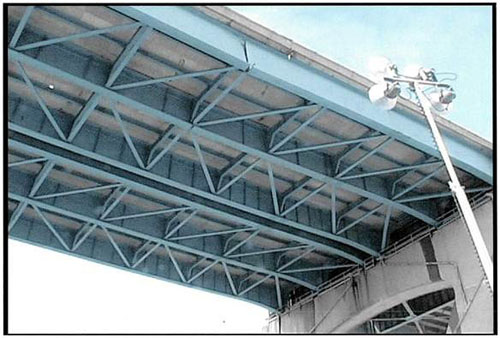
Figure 1 Underside of the South Approach Span Showing the Fractured Girders
The failure analysis effort began with a brief close-up visual inspection of the fractures. After the span was removed by explosive demolition, sections of the cracked girders were dismantled and sent to the FHWA Turner-Fairbank Highway Research Center (TFHRC) and Lehigh University for evaluation. Material properties were thoroughly evaluated and fractographic and metalographic studies were performed. The investigation also included detailed structural analysis, local stress analysis, fracture mechanics analysis and some live load testing of other sections of the structure.
Significant Finding from the Investigation
The crack surfaces were examined under high magnification using a scanning electron microscope. The failure mode was positively identified as brittle, cleavage fracture. The fractures occurred suddenly and propagated through the girders at an explosive rate.
The fractures initiated in the web plate, most likely the interior girder, at the joint where the lower lateral bracing system framed into the web. The initiation site was located in the gap between the gusset (shelf) plate and the transverse connection/stiffener plate. Figure 2 shows a view of the joint assembly where the fracture initiated.
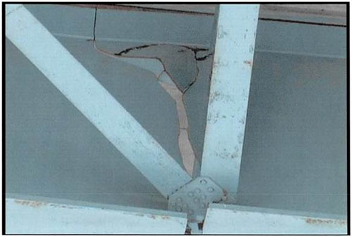
Figure 2 Joint assembly where the lateral brace system frames into the girder web.
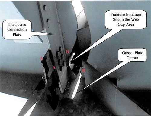
Figure 3 Fracture initiation site in the web gap Area.
There was no evidence of fatigue cracking prior to fracture initiation. This indicates that there was no observable damage prior to the sudden fracture. Even the most rigorous fracture critical inspection would not have provided warning of the impending fracture.
The web material properties met modem standards for A36 steel. Toughness met the 2001 AASHTO requirements for zone 2, fracture critical use.
The flange material properties met modem properties for A588 steel. Toughness met the 2001 AASHTO requirements for zone 2, non-fracture critical use.
Subsequent weigh-in-motion testing on a detour route indicated that the average truck weight was approximately 80 kips with a (±)20 kip variation. Structural analysis and field-testing showed that type of live load applied to the Hoan Bridge would have produced a relatively low live load stress range. The stress due to the sum of all loads (DL+LL+WL+Thermal) was probably within acceptable design limits for the bridge.
A narrow gap between the gusset plate and the transverse connection/stiffener plate created a local triaxial constraint condition and increased the stiffness in the web gap region at the fracture initiation site. This constraint prevented yielding and redistribution of the local stress concentrations occurring in this region. As a result, the local stress state in the web gap was forced well beyond the yield strength of the material. Under triaxial constraint, the apparent fracture toughness of the material is reduced and brittle fracture can occur under service conditions where ductile behavior is normally expected.
The first fracture probably initiated in the interior girder in the narrow web gap formed by the detail. The dynamic toughness of the interior girder flange was insufficient to arrest a high rate fracture initiating in the web. The web fracture continued to propagate through both girder flanges and completely severed the girder. This set off a chain reaction that causes fractures to initiate in the web gaps of the two exterior girders. The fracture continued through the flanges in the east exterior girder, but arrested in the flanges of the west exterior girder. The dynamic fracture toughness of the exterior girder flanges is high enough that crack arrest is possible depending on the load level. The reason arrest occurred in only one of the exterior girders can be explained by unequal re-distribution of loads during the failure sequence.
Inspection reports indicate that web cracks were found in other locations of the bridge as early as 1995. The cracks were thought to be fatigue cracks and retrofit actions were taken based on this assumption. The forensic investigation has determined that these prior cracks were fractures similar to the ones resulting in failure. However, all prior web cracks arrested at the flange and didn't trigger the chain reaction failure.
Significance of Factors Involved in the Failure
The joint connecting the lower lateral bracing to the web is clearly the initiation site of failure in the Hoan. There are many known cases of fatigue cracking from this type of detail, but this is the first known case of brittle fracture. The Hoan bridge case is unique in that there was no evidence of fatigue prior to failure. The forensic investigation has studied all of the factors present at the time of failure and a relative assessment can be made regarding their significance in the failure process. It took a combination of factors to add up and cause the chain reaction failure, but some are more significant than others in the process.
Joint Details
The primary cause of fracture initiation was determined to be the geometry and fabrication tolerance of the joint where the lateral bracing frames into the web. The joint was detailed with a narrow web gap that caused a local high constraint, increased stiffness, and reduced the apparent fracture resistance. As ideally detailed, the joint has only l/8 in. separating the welds on the two plates. The fabrication tolerance resulted in reduced gaps as well as intersecting welds in many locations throughout the structure. Stress analysis showed that the intersecting welds increased the rigidity of the joint and made the constraint problem worse. This non-ductile behavior in the joint caused by a triaxial constraint and state of stress has never been documented before as being a potential problem in bridge detailing. This is the first time this problem is being reported.
Additionally, the "K" pattern in the lower lateral brace system introduces an axial force in the girder to satisfy equilibrium in the joint area. A stress analysis showed that this increased the live load stress range at the outside ends of the shelf plate, but that there was little effect in the gap area.
Retrofit Hole
An asymmetric hole was drilled in one side of the shelf plate at the joint where failure initiated. This hole caused a further increase in stress concentration at the point where the failure initiated. Because fractures were also found to have initiated in joints without the hole, the presence of the hole is relatively insignificant.
Effect of Truck Loading
Weigh in motion results indicate that overloaded trucks were probably common along the bridge route. However, the live load stress ranges in the gap area would have been relatively small compared to the dead load stress. This is consistent with the fact that no fatigue cracking was observed at the failure sites. Analysis shows the stress at the failure location was probably within design limits. Therefore, any overloaded trucks on the bridge at the time of girder failure probably had a minor role in the failure.
Effect of Temperature
Without high constraint, the web plate toughness is sufficient to prevent fracture initiation down to the lowest anticipated service temperature of -30°F. The constraint in the joint assembly causes a reduction in fracture initiation resistance that is relatively insensitive to temperature. Therefore, low temperature probably had a minor effect on the fracture initiation, but it significantly reduced the ability of the structure to arrest dynamic cracks. The failure sequence where multiple fractures caused the structure to unzip would have become less likely at higher temperatures.
This is supported by the fact that the dynamic fracture resistance of the flange plates was shown to decrease rapidly as a function of temperature. Therefore, temperature had a significant effect on the ability of the flanges to arrest cracks. At higher temperatures, the probability of crack arrest increases significantly. The low temperature at the time of failure was the significant factor that allowed the web fracture to progress to a chain reaction failure of the structure. It is noted, however, that the toughness specification used for bridge steels is based on preventing fracture initiation, not crack arrest.
Attachment B
Assessment of Other Structures
The connection where the lower lateral brace system framed into the girder web was identified as the fracture initiation site in the Hoan Bridge. Although this general type of connection is used in many bridges, this is the first known case where fracture occurred without pre-existing fatigue cracks. This suggests that the Hoan Bridge is a relatively unique case. Assessment of the vulnerability of other structures is complicated because of the wide variation in the geometric details and fabrication quality between structures. Research is underway to develop guidelines for assessment. However, two factors have been identified from the Hoan Bridge that can be used to screen other structures. This document should be considered preliminary guidance until more information is available.
1) Intersecting Welds Betweed Transverse and Longitudinal Attachments in Tensions Areas
Figure 1 shows a top view of the connection details used in the Hoan Bridge. The gusset plates have a 1-1/2 in. slot cut to clear the % in. transverse connection/stiffener plate. The resulting web gap is 3/8 in. on each side of the connection/stiffener plate if the gusset plate is perfectly centered during fabrication.
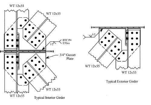
Figure 1 Lateral brace connection for the exterior and interior girders of the Hoan Bridge.
The gusset plate causes a large stress concentration in the web gap area. On the short side of the gusset plate, the transverse WT12x55 lateral brace is bolted both to the gusset plate and the transverse connection/stiffener plate. This creates a positive attachment between the two plates and minimizes any added stress due to out-of-plane distortion.
Finite element analysis has shown that minor changes in web gap size have a very large effect on constraint. Figure 2 shows two web gap conditions that were observed in the Hoan Bridge. Case A shows a perfectly centered gusset plate resulting ideally in a small gap between the fillet weld toe on the transverse connection/stiffener plate and the partial penetration weld on the gusset plate. In case B, the gusset plate was offset, allowing the gusset plate weld to touch the toe of the fillet weld on the connection plate. When a gap exists between the two welds, this results in the normal condition of biaxial constraint where the web is free to yield under high stress concentrations. When the gap is reduced to zero, this creates a triaxial constraint condition and increases the stiffness in that localized region. The difference in gap has little effect on the stress concentration determined from linear elastic analysis. However, non-linear plastic analysis revealed that there is a large difference in the plastic constraint. In case A, the elastic stress concentration is relieved by local yielding of the web in the gap area. In case B, triaxial constraint prevents yielding and the stress level increases to levels several times the yield strength of the web. This explains the explosive rate of the fracture as the energy is released from the constraint once fracture is initiated.
The size of the weld connecting the gusset plate to the web is also expected to have a significant effect on constraint level. The Hoan Bridge has a 1/2 in. partial penetration weld connecting the gusset plate to the web. Fillet welds connecting the gusset plate to the web should result in a less severe constraint condition. This effect is being studied through on-going research.
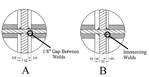
Figure 2 Small changes in web gap has a large effect on constraint.
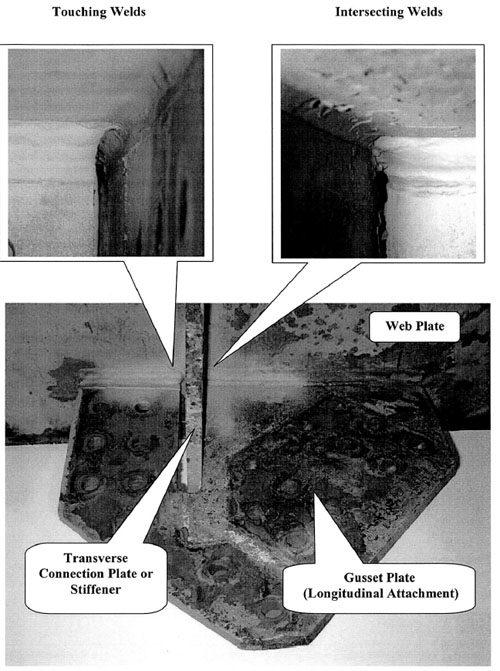
Figure 3 Examples of contact between longitudinal and transverse welds.
The results indicate that the case where the welds touch or intersect has a much higher constraint level than the case where there is a small gap between welds. This indicates that touching or intersecting welds in the web gap area should be considered an indicator of possible constraint problems. Intersecting welds also increase the likelihood that weld defects will be present in the web gap area. Even a small gap appears to be sufficient to relieve constraint and reduce the vulnerability to fracture.
Figure 3 shows a typical gusset plate detail from the Hoan Bridge with the lateral bracing removed. Typical examples of touching and intersecting welds are shown in the insets. In addition to gusset plates, any detail where longitudinal web attachments come close to transverse attachments should also be considered vulnerable to constraint problems. At the present time, any details where longitudinal and transverse plates terminate close together in should be examined for intersecting and touching welds. This only applies to sections of the structure where there is a net tensile stress due to the combination of all loads. Details in areas of compressive stress will not be vulnerable to fracture.
The case where the gusset plate is positively attached to the transverse plate (i.e. welded all around) should be considered differently than the case where no positive connection exists between the two plates. This type of connection will be less vulnerable to brittle fracture, but intersecting and overlapping welds may lead to fatigue cracking. This type of connection is currently being studied through FHWA research.
2) Rapid Observed Crack Growth
Most cracks found during inspection of structures are caused by fatigue. Under normal conditions, fatigue cracks initiate from microscopic flaws and slowly grow larger under the effects of live load. The rate of growth is proportional to the stress range and frequency of loading on the structure. Geometry also has an effect on crack growth rate. Cracks located near details that cause stress concentration grow faster than those out in undisturbed areas of a steel plate. These conditions vary between structures and it is difficult to estimate a generic crack growth rate for all cases. However, the conditions present in bridge structures almost always result in slow, stable crack growth rates.
Crack extension by brittle fracture is different. The cracks immediately "pop" into the structure and crack growth occurs instantly in an unstable, dynamic fashion. In some cases, brittle fractures arrest in the structure; in other cases they result in full fracture of a structural member. In cases where crack arrest occurs, the resulting crack cannot be distinguished from a fatigue crack based on visual inspection of the surface of the structure. In some cases, an arrested fracture will become a fatigue crack and continue to slowly extend in a stable manner.
Brittle fractures occurring any place in a structure is a very serious safety concern. These can cause immediate loss of part or all of the capacity of the structure and in the worst case will cause collapse. The Hoan Bridge is a rare example of the worst-case scenario.
Fatigue cracks are still a cause for concern because they will continue to grow and eventually reach a size where brittle fracture will occur. However, the fracture control plan in the AASHTO specifications and the bridge inspection program work together to insure that fatigue cracks can be found and repaired before they become critical.
Large amounts of crack growth in a given inspection interval should be considered a warning sign that cracks may be the result of brittle fracture, not fatigue. It is difficult to define what constitutes large amounts of crack growth since it depends on a number of conditions that vary between structures. Research is underway to provide better guidance in this area. Lacking other information, any crack growing more than 6 inches in any given inspection cycle should be considered cause for more detailed evaluation. The experience of bridge inspectors should also be considered if they are reporting abnormally large crack growth compared to their experience with similar conditions. This should also apply to new cracks that are observed to be more than 6 in. long at the time they are discovered. It is possible that cracks could have existed for some time and that they were not detected in earlier inspections. However, this should not be assumed, particularly if the cracks are located in a narrow web gap area.
Recommended Actions
Structures that are known to have narrow web gaps in tension zones should be inspected closely with a hands-on visual inspection. This can be accomplished by review of inspection reports as long as there is sufficient photographic documentation to assess the gap area. If intersecting or touching welds are identified or suspected, steps should be taken to further evaluate the connection and consider possible retrofit options. In cases where there is a clear gap between the two welds, the susceptibility to constraint-induced fracture is lower. Retrofits are probably not required unless inspection reveals fatigue cracking in the gap area.
Retrofit options can include hole drilling and/or grinding to separate the welds and eliminate the weld intersection. This option needs to be performed with caution, since widening the web gap can make the connection more flexible and vulnerable to distortion-induced fatigue.
Other options include complete removal of the lateral brace system and gusset plates similar to the retrofit being performed on the Hoan Bridge. This requires a detailed engineering analysis to determine if the lateral system is needed for performance of the structure. Relocation of the lateral system attachment to the bottom flange can also be considered in cases where analysis shows the lateral system is required.
The urgency of the need to retrofit intersecting welds should be considered on a case-bycase basis. Structures with years of service and no observed problems are less critical than those where there is a history of cracking. Any structures with evidence of rapid crack growth from intersecting welds should be considered urgent for further evaluation.
If rapid crack growth is observed, it should not be assumed that the cracks are caused by fatigue. At a minimum, a core sample should be removed from the structure that contains a portion of the crack. The sample should be evaluated by a testing laboratory that has experience in failure analysis of metallic structures. If the cores are taken at the tip of the crack, the resulting hole can serve to prevent further crack growth. It will also be desirable to take a core sample several inches back from the crack tip. This can identify cases where brittle fractures arrest and continue to extend under fatigue. If brittle fracture is identified from the core samples, this should be considered cause to perform an immediate safety evaluation of the structure. The urgency of this evaluation increases at times when the structure may experience cold service with temperatures.