

Design Guide for Precast UHPC Waffle Deck Panel System, including Connections
CHAPTER 5. FABRICATION/PRODUCTION, CONSTRUCTION, AND INSTALLATION
Prefabrication
All UHPC waffle panels should be prefabricated at a precast plant that has prior training in UHPC mixing and casting from the UHPC material provider. The panel fabrication involves several steps related to assembly of formwork to create the necessary void patterns or rib spacing, placement of transverse and longitudinal reinforcement, placement of dowel bars at the transverse and longitudinal joint locations, creating voids for shear pockets, batching and casting of UHPC, and steam curing of the final product. A panel fabrication process is shown in figure 73.
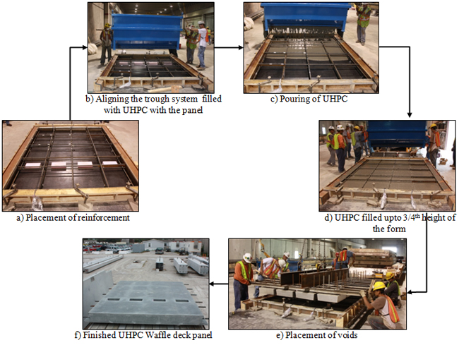
Figure 73. Photos. Construction of a UHPC panel.
Formwork
A specially designed, displacement-type formwork made of steel sections with adjustable rib spacing is recommended for the UHPC waffle deck panel fabrication, which is different from the formwork used typically for full-depth solid precast deck panels made of normal concrete.
The steel formwork is necessary to maintain the desired tight tolerances because of the thin UHPC sections in the waffle deck panels. In addition, the adjustable steel forms facilitate multiple waffle configurations, decreasing the production cost of the panels. It is suggested that panels be cast upside down using a formwork consisting of two parts, as shown in figure 74.
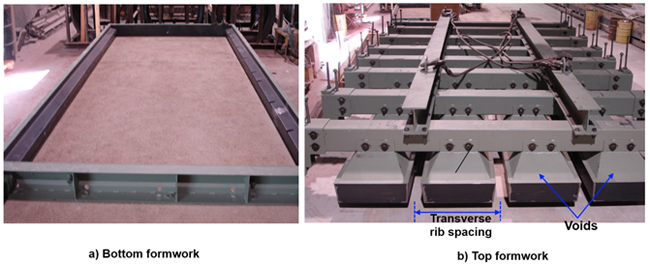
Figure 74. Photos. Formwork used for waffle deck panel construction.
The top formwork consists of blocks used to create the waffle voids, which can be adjusted to create the required rib spacing in both panel directions. The bottom formwork is a basic open-top design.
Reinforcement
The longitudinal and transverse reinforcement is placed in the bottom form, before it is filled with UHPC. The high bond strength and excellent durability properties of UHPC eliminate the need for using standard hooks and epoxy-coated special reinforcement.
While placing the transverse and longitudinal reinforcement, as well as dowel bars along the joint edges, tight tolerances should be exercised due to the cover requirements and the presence of thin rib sections in the waffle deck panel. The use of corrosion-resistant reinforcement may help in relaxing the tolerance limits for the longitudinal and transverse reinforcement without affecting the overall durability of the deck panel.
Batching UHPC
UHPC may be batched using a variety of different types of mixers. However, it is recommended to seek advice from the UHPC manufacturer regarding the energy demand on the mixer and any modifications required to mix large amounts of UHPC. Due to the properties of UHPC, it requires relatively high energy for mixing, thus subjecting the mixer to higher torque demands than normal. Precast producers must obtain training from the UHPC manufacturer prior to producing UHPC elements regarding batching of UHPC. The UHPC material batched according to the manufacturer specifications typically achieves a minimum dynamic flow of 8 to 9 inches (using the flow table described in ASTM C230).
Casting of the UHPC Panel
It is important to utilize the self-consolidating and self-leveling nature of UHPC. It can be placed with little to no vibration (depending on the flow), and the direction of casting/hopper configuration will dictate the fiber orientation. It is recommended to cast the waffle deck upside down (driving surface down) to facilitate a flat, uniform riding surface as well as allowing for the displacement casting of the waffle voids. Displacement casting of the voids is crucial to ensure a crack-free, durable waffle panel.
Using this casting technique, the bottom form is filled with UHPC to a depth of 4.5 inches (for an 8-inch-deep waffle panel), and the top formwork is then pushed into the UHPC, causing it to displace and form the ribs. The bottom formwork should be a basic open-top form and be fastened adequately to the casting bed, to prevent lifting of the bottom form due to pressure developed in the displacement process. The voids should be removed once the UHPC initial set is achieved (typically 12 to 14 hours after pouring). This will allow for the shrinkage to take place without any restraint, thereby preventing crack development in the deck panel.
In addition, the UHPC panels should be covered with plastic sheeting to prevent dehydration of the exposed surface. If the designer chooses to integrate a riding surface into the waffle deck panel instead of using an overlay wearing surface, adequate attention should be given to create the necessary riding surface using standard form liners or other suitable materials placed in the bottom form.
Curing of the Waffle Panel
Similar to conventional concrete, the strength gain of UHPC is influenced by the curing temperature. For handling the UHPC panels in the precast yard, a minimum compressive strength of 14,000 psi is typically recommended. To reduce the curing time needed to achieve this strength, the panels can be tented after casting and cured at 90 °F. On the Wapello County, Iowa, project, this additional step decreased the required curing time from 4 days to 2 days.
Once the UHPC reaches 14,000 psi, the panels should be moved to a curing area and subjected to a controlled steam cure at 195 °F with 95 percent relative humidity for 48 hours, as recommended by the UHPC material manufacturer. This steam cure will enhance the UHPC to its ultimate strength and durability characteristics, surpassing a minimum design compressive strength of 24 ksi.
Fabrication of Shear Pocket
A few recommendations are presented for consideration when specifying the fabrication of shear pockets. As noted previously, either full- or partial-height shear pockets can be used, where partial-height pockets do not extend through the top surface of the precast deck. Examples of both partial- and full-height shear pockets are shown in figure 75.
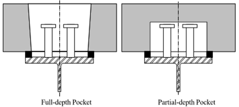
Figure 75. Diagrams. Full- and partial-depth shear pockets.
If no overlay is intended to be provided, partial-height shear pockets are recommended for protection from water leakage at the shear pocket/grout interface and for aesthetic reasons. When partial-depth pockets are used, the following criteria are recommended to be satisfied for precast decks: minimum 1/2-inch clearance between the highest point of the shear connector and the pocket and 2-inch minimum distance between the highest point of the shear connector and the top surface of the panel. In addition, injection ports and vents should be provided in partial-height pockets.(50) Furthermore, to avoid stress concentrations at the corners of the shear pockets, which could initiate cracking, the corners of the shear pockets can be rounded.(56)
Although identified previously as a preferred option, oval pockets often are more expensive to fabricate, but the additional cost is usually insignificant. When UHPC waffle deck panels are used in conjunction with in situ UHPC infill, it has been shown that rectangular pockets can be used reliably. Furthermore, both full- and partial-height shear pockets may be used.
If partial-height pockets are preferred, it must be ensured that there is sufficient dimension for the access hole to get UHPC in and fill the joint in a reasonable amount of time. In addition, the length of shear studs and extension of reinforcement into the pocket can be reduced due to the high compressive and bond strength of UHPC.
Overlay
Often, a thin epoxy polymer or modified concrete overlay is applied over precast deck panels after deck installation or replacement procedures have been completed. By providing an overlay, the panels, joints, and connections between precast elements are further protected from water and deicing chemicals, which, when used in harsh winter climates, can contribute to the deterioration of concrete and corrosion of reinforcing steel. UHPC shows promising durability characteristics suggesting that chemical corrosion may not be a major issue; however, specifying an overlay provides an additional measure of protection against potential durability issues.
In addition, due to the necessary transverse connections between deck panels, the riding surface on precast deck panel bridges may not meet specific requirements for rideability; an asphalt or concrete overlay can mitigate this issue and provide a smooth, comfortable riding surface for motorists.
Some of the suggested recommendations from the Utah DOT for the application of a thin polymer overlay on precast concrete deck panels can be utilized for UHPC waffle deck panels. These recommendations include selecting a minimum thickness of overlay of at least 1/2 inch, applying the overlay in at least two coats to obtain minimum thickness, and providing overlay joints that are not coincident with deck panel connections.(61)
With the UHPC panels, as observed in the Wapello County project, the overlay can be eliminated completely by grinding off any excess of the in situ UHPC poured in the joints to make a smooth transition between the panels and connections, thus providing an acceptable riding surface.
The suitability of different riding surfaces was investigated as part of this HfL project. The rideability and surface characterization of six different waffle deck surface finishes were investigated by measuring the skid resistance values (SRVs) and surface texture depth. Five of the textured surfaces were characterized using the standard sand patch test. The details of the textures investigated are presented in table 22 along with average values of measured sand patch diameter and texture classification.
| Sample No. | Texture / (Brand) | Sand patch diameter (in.) | Average sand patch diameter (in.) (d) | Texture depth (in.)* = x 103 |
|---|---|---|---|---|
| 1 | 2/61 Thames / (Rekli) | 9.44, 8.66, 8.46, 8.86 | 8.86 | 0.0496 |
| 2 | Broom finish / ( Architectural Polymers) | 10.03, 9.25, 9.64, 9.05 | 9.50 | 0.0429 |
| 3 | 2/102 Parana / (Rekli) | 7.87, 7.68, 7.87, 8.07 | 7.87 | 0.0626 |
| 4 | Heavy Broom finish / ( Architectural Polymers) |
6.3, 6.3, 6.1, 5.91 | 6.15 | 0.1027 |
| 5 | Anti Skid / (Fitzgerald Form liners) | 8.66, 8.86, 9.05, 9.05 | 8.91 | 0.0488 |
SRVs for different surface finishes were measured with the British pendulum tester using the ASTM E303 standard method for measuring the surface friction properties. The skid-resistant test was performed on all six different texture surfaces with four tests per sample. In all tests, a minimum 12-inch by 12-inch sample size was used. The details of the test setup are shown in figure 76.
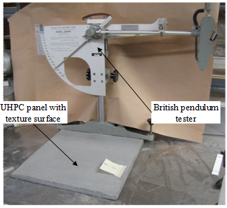
Figure 76. Photo. Test setup for characterization of skid resistance of textures using the British pendulum tester.
The details of the different textures tested and their mean SRV values are provided in table 23.
| Sample No. |
Texture / (Brand) | Texture | Skid Resistance Values (BPN) | Average SRV | ||
|---|---|---|---|---|---|---|
| 1 | 2/61 Thames / (Reckli) | 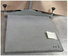 |
87,88,88,88 | 87.75 | ||
| 2 | Broom finish / (Architectural Polymers) | 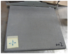 |
72,70,70,70 | 70.5 | ||
| 3 | 2/102 Parana / (Reckli) | 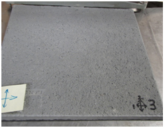 |
Direction-1 |
96,96,96,96 | 96 | |
Direction-2 |
90,90,90,90 | 90 | ||||
| 4 | Heavy Broom finish / (Architectural Polymers) | 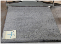 |
Direction-1 |
72,75,75,75 | 74.25 | |
Direction-2 |
80,81,80,81 | 80.5 | ||||
| 5 | Anti Skid / (Fitzgerald Form liners) | 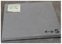 |
80,80,80,81 | 80.25 | ||
| 6 | Carpet / (Fitzgerald Form liners) | 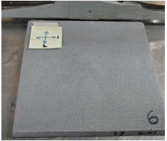 |
Direction-1 |
62,65,65,65 | 64.25 | |
Direction-2 |
76,75,78,80 |
76.625 |
||||
Based on the suggested minimum values of skid resistance by the Transport and Road Research Laboratory, all of the tested texture surfaces surpass the minimum required SRV value of 65, satisfying the rideability criteria.(62)
Figure 77 shows a close-up view of the bridge deck surface from the bridge in Wapello County, Iowa. It depicts the smooth transition between the connections and prefabricated waffle panels. Of the different riding surfaces summarized in table 23, 2/102 Parana texture was selected for implementation in the Wapello County project.
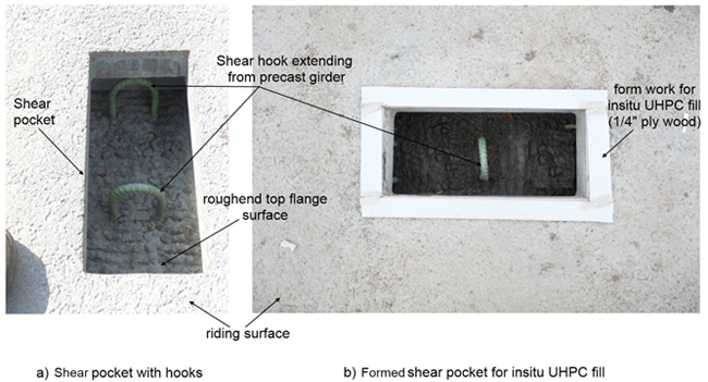
Figure 77. Photo. Close-up of shear pockets and shear hooks at Wapello County, Iowa, waffle deck bridge.
Field Installation
This section describes the steps for installing the UHPC waffle deck panels in the field, which are primarily based on the experience gained in Wapello County.
The precast deck panels were designed to be fully composite with the precast prestressed concrete girders. This was accomplished by providing shear hooks in the precast girder at the shear pocket locations, which were subsequently filled with UHPC (see figure 77).
Following installation of the girders, the half-width precast deck panels are set to grade, spanning between the concrete girders and leveled to the needed elevation by placing shims. At the panel bearings on the beams, an Evazote foam strip is installed to provide a good contact and watertight seal between the precast panels and prestressed concrete girder (see figure 78). Quick-setting spray foam is used to create the watertight seal between panels and girders.
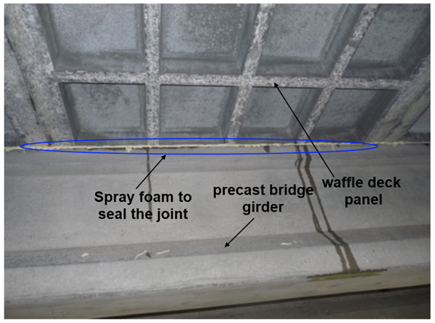
Figure 78. Photo. Watertight seal at panel-to-girder connection using quick setting spray.
Once all panels are installed and tested for moderate water tightness, the connection regions are prepared for field casting of UHPC fill material. Figure 79 shows the installed waffle panels at the Wapello County bridge.
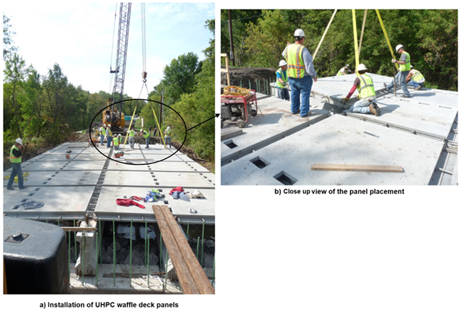
Figure 79. Photos. Placement of waffle deck panels.
The faces of the precast panels were sandblasted at the precast plant to create a roughened surface to enhance the bond between the precast panel and the joint fill, leading to water tightness of the transverse joint (panel-to-panel joint). In addition, the surface of each precast panel was soaked to saturate surface-dry (SSD) prior to casting the joint fill. Figure 80 provides a close-up view of the transverse and longitudinal connections in the Wapello County bridge.
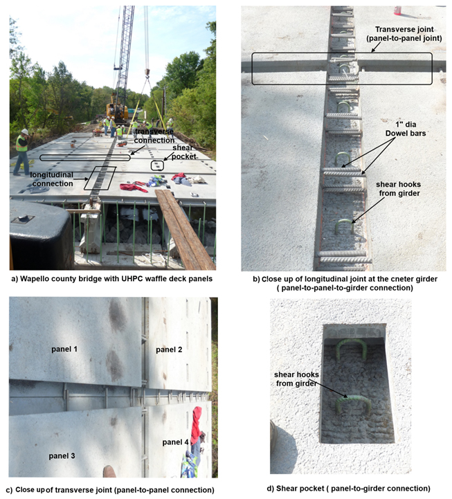
Figure 80. Photos. Transverse and longitudinal connections.
The UHPC joint fill materials were delivered to the site by the material supplier and set up for batching (see figure 81). A pair of IMER Mortarman 750 mixers was used to batch the in situ joint fill UHPC material. Each mixer was capable of producing 5.12 cubic ft of UHPC per batch, with an average mixing time of 20 minutes. The mixers were run in parallel just off the end of the bridge, providing a continuous supply of UHPC material and maintaining direct access to the bridge deck. The number and size of mixers needed on a bridge site is determined by the daily joint fill volume requirements of the contractor.
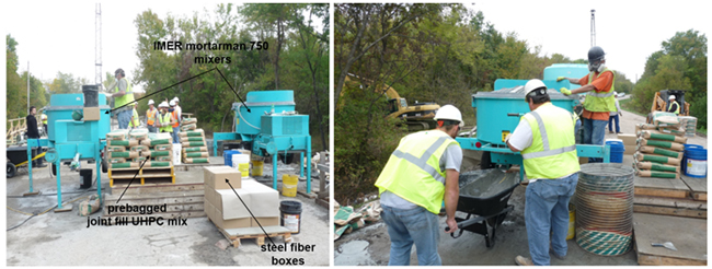
Figure 81. Photos. Batching of UHPC joint fill using IMER Mortarman 750 mixers in field.
The UHPC joint material can be transported to the joints by a power buggy or a wheelbarrow and then placed directly into the joints and shear pockets (see figure 82a). UHPC joint material flows along the longitudinal and transverse joints due to its self-consolidating and self-leveling behavior (see figure 82b). The UHPC should not be vibrated, as that would potentially disrupt the random orientation of the fibers. The completed panel-to-girder shear pocket connections are shown in figure 82c, while figure 82d shows the partially filled longitudinal panel-to-girder connection at the centerline of the bridge.
The white colored strips that can be seen in figure 82 are made from a rigid, waterproof material and have multiple purposes. They provide a 1/4-inch overfill of the UHPC in the joint. As the air entrapped during mixing and placing escapes, the grout settles closer to the top surface of the bridge deck, minimizing further addition of UHPC. Escaped air forms bubbles on the top surface of the connections. The overfill provides a surface slightly above precast panels such that it can be ground completely flush with the deck surface to remove any imperfections.
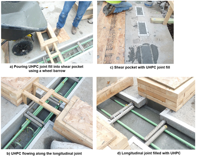
Figure 82. Photos. Filling of connection regions with in situ UHPC and completed connections.
The joints are covered with form-grade plywood strips to prevent any moisture loss during initial setting (see figure 83) and then allowed to cure until reaching 15,000 psi before opening to traffic. The time needed to reach that compressive strength for the joint fill UHPC material varies depending on the ambient temperature. Typically, at ambient temperatures around 68 °F, a minimum of 4days is needed to reach the desired strength. This time can be reduced by using accelerators or providing external heating sources (such as propane heaters or glycol heating lines).
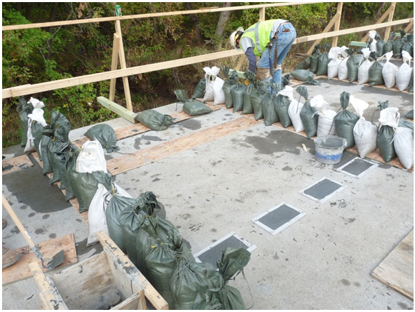
Figure 83. Photo. Finished transverse connections (panel-to-panel connection) covered with plywood.
During the field curing process, the UHPC material should be ground smooth to remove any high spots and/or overfill. It is critical to grind the connection regions while they are relatively soft (around 5,000 psi); otherwise, the UHPC will be hard on grinding equipment. This early grinding can only be conducted using hand-operated equipment. If the grinding equipment is mounted to a truck, the UHPC must possess vehicular loading strength prior to grinding. Figure 84 shows the surface aspect after grinding. Freckling of the surface may appear where any fibers are exposed to weather due to grinding; this does not have an impact on the overall performance of the joint.
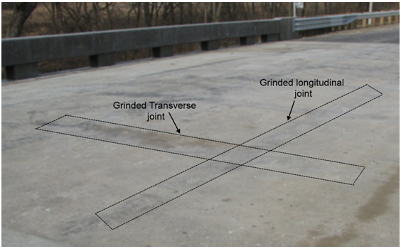
Figure 84. Photo. Close-up of the waffle panel deck after grinding along the transverse and longitudinal deck connections.