The Implementation of Full Depth UHCP Waffle Bridge Deck Panels
PHASE I FINAL REPORT
April 2, 2010
Prepared by
Coreslab Structures, (Omaha), Inc.
Sponsored by
Federal Highway Administration, Highways for LIFE
Technology Partnerships Program
Table of Contents
- Introduction
- Work Completed in Phase One
- Work Scheduled for Phase Two
- References
- Appendix A: Structural Characterization of UHPC Waffle Bridge Deck Panels and Connections
- Appendix A: Waffle Deck Panel Fabrication
- Appendix A: Experimental Investigation
- Appendix A: Summary and Conclusions
| 1. Report No. | 2. Government Accession No. | 3. Recipient's Catalog No. | |
| 4. Title and Subtitle The Implementation of Full Depth UHPC Waffle Bridge Deck Panels Phase 1 Report |
5. Report Date March 30, 2010 |
||
| 6. Performing Organization Code | |||
| 7. Author(s) John Heimann & George Schuler |
8. Performing Organization Report No. | ||
| 9. Performing Organization Name and Address Coreslab Structures (Omaha) Inc. 802 Allied Rd. Bellevue, NE 68123 |
10. Work Unit No.(TRAIS) | ||
| 11. Contract or Grant No. DTFH61-09-G-00006 |
|||
| 12. Sponsoring Agency Name and Address Federal Highway Administration Highways for LIFE Technology Partnerships Program |
13. Type of Report and Period Covered Dates Covered: 6/15/2009 – 3/31/2010 |
||
| 14. Sponsoring Agency Code | |||
| 15. Supplementary Notes Technical aspects of this report regarding testing and performance of the system can be found in the University of Iowa State InTrans Report IHRB TR-614. |
|||
| 16. Abstract In the U.S. today, there are over 160,000 bridges that are structurally deficient or obsolete with more than 3,000 new bridges added each year. Federal, State and municipal bridge engineers are seeking new ways to build better bridges, reduce travel times, and improve repair techniques; thereby reducing maintenance. Additionally, owners are challenged with replacing critical bridge components, particularly bridge decks, during limited or overnight road closure periods. The use of Full Depth UHPC Waffle Deck Panels is currently gaining significant interest amongst numerous State DOT's and the Federal Highway Administration as a possible solution to these challenges. The first implementation of this system on a U.S. roadway will be made possible by this grant's funding. The objective of this research is to confirm that this system is a viable solution to the problems encountered by design engineers. It is hoped that the Full Depth UHPC Bridge Deck System will revolutionize the way bridges are designed in North America. The implementation of this system is broken up into two phases within the overall scope of this project. Phase 1 includes the design and testing of a mock-up bridge section for verification of design assumptions, as well as, evaluating the feasibility of manufacturing and installing the deck elements. Phase 2 will consist of a full scale two-lane bridge on a secondary road in Wapello County, Iowa constructed of prestressed concrete girders and 14 UHPC deck panels. |
|||
| 17. Key Words UHPC, Waffle Slab, Bridge Deck, Highways for LIFE |
18. Distribution Statement No restrictions. |
||
| 19. Security Classif. (of this page) Unclassified |
20. No. of Pages 72 |
21. Price | NA |
Introduction
In the U.S. today, there are over 160,000 bridges that are structurally deficient or obsolete with more than 3,000 new bridges added each year.(1) Federal, State and municipal bridge engineers are seeking new ways to build better bridges, reduce travel times, and improve repair techniques; thereby reducing maintenance. Additionally, owners are challenged with replacing critical bridge components, particularly bridge decks, during limited or overnight road closure periods.
In response to these challenges, researchers at the FHWA Turner Fairbanks research facility began investigating potential solutions in the year 2000. Prototype designs of full depth Ultra High Performance Concrete (UHPC) waffle deck panel systems have been in development over the past three years in both Europe and the United States.
The use of UHPC provides superior durability against chlorides, freeze-thaw effects, salt scaling, abrasion, accidental impact, fatigue, and overload, thereby extending the useful life of the bridge deck. Combining these positive attributes of UHPC and the efficiency of the waffle panel design provides an extremely durable option that enables faster construction and longer girder spans through the efficient use of materials and reduced weight. In addition to these benefits, the UHPC Waffle bridge deck system is applicable to both new construction and the rehabilitation of existing deteriorated bridge decks. The use of this solution for existing bridge rehabilitation not only restores the deck, but also provides opportunities for upgrading the load capacity of existing bridges, through the improved strength and reduced deck dead load.
The use of Full Depth UHPC Waffle Deck Panels is currently gaining significant interest amongst numerous State DOT's and the Federal Highway Administration (FHWA). By demonstrating this system is a viable solution to the problems encountered by design engineers it is hoped that the Full Depth UHPC Bridge Deck System will revolutionize the way bridges are designed in North America.
The implementation of the system in this project is broken up into two phases. Phase 1 includes the design and testing of a mock-up bridge section for verification of design assumptions, as well as, feasibility of manufacturing and installation of the deck elements. Phase 2 will consist of a full scale two-lane bridge on a secondary road in Wapello County, Iowa constructed of prestressed concrete girders and 14 UHPC deck panels. The following sections describe the results of Phase 1 and the upcoming events and schedule of Phase 2.
Work Completed in Phase One
The following sections summarize the progress that was made throughout Phase 1 of the project. As mentioned previously, the objectives of Phase 1 were to prototype and model the demonstration bridge planned for Phase 2. These objectives were met by producing two prototype UHPC waffle deck panels based on preliminary design work completed by the Iowa Department of Transportation (IDOT), modeling the section of the demonstration bridge that would undergo testing in Phase 1 using a Finite Element Analysis (FEA) to predict the response of the system and, load testing the prototype waffle slabs to confirm the design assumptions and FEA validity.
Waffle Panel Design and Fabrication
The design of the waffle slab was completed by the IDOT in late August of 2009, and shop drawings for use by Coreslab Structures (Omaha) Inc. production staff were complete by early September. Coreslab Structures and Lafarge North America consulted on the fabrication and aspects of the design relating to ease of production and requirements for UHPC joint fill respectively. The prototype panels were 8'-0" wide by 9'-9" long, with a number six bar in the top and a number 7 bar in the bottom of each rib (See Figure 1 below). One girder to girder span along the length of the bridge was modeled by the prototype panel. It was determined that two slabs would be necessary to test the transverse panel to panel joint.
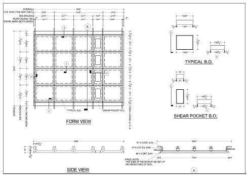
Figure 1: Prototype Panel Shop Drawing
The two prototype panels were produced in mid September 2009 at the Coreslab Structures plant in LaPlatte, NE, with the assistance of Lafarge North America's technical representative. The panels were cast using a displacement technique where the form was filled with fluid UHPC. The voids which make the ribs of the panel were forced downward into the UHPC to displace the material creating the shape of the panel. This technique was used to allow for the removal of the voids once the UHPC reached initial set, which is necessary to allow for unrestrained shrinkage and also to maintain the random orientation and consistent meshing of the fiber reinforcement. An additional benefit of casting the panels in an inverted orientation is that the final driving surface will be cast into the panels through the use of a form liner. By eliminating the application of a wearing surface placed in the field, the cost of the system is further reduced. Figures 2 through 6 depict the casting and production sequence.
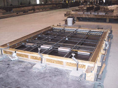
Figure 2: Final Form Setup
Figure 2 shows the reinforcing layout of the first casting. Uncoated reinforcing was used due to the fact the UHPC is effectively impermeable, eliminating the need for epoxy coated, galvanized, or stainless steel reinforcing to resist corrosion. The prototype panel formwork was made of wood in order to provide an inexpensive and temporary form. This strategy was employed due to the fact the design was preliminary and changes to the rib size, spacing, and joint profiles were possible between the prototype and demonstration panels. The final formwork will be made of steel and adjustable to fit different rib spacings for various panel configurations. In addition to the standard reinforcing, several monitoring instruments were also cast into the panels to monitor the internal responses of the UHPC and reinforcing.
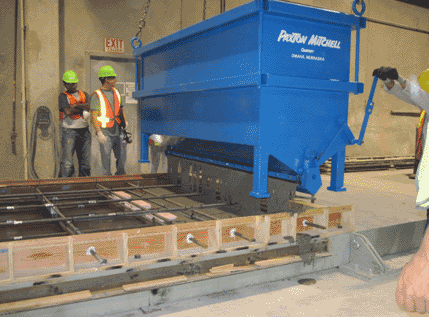
Figure 3: Casting
Figure 3 shows the placing of the UHPC into the form. The UHPC was placed with a specially designed bucket that is as wide as the form, which aligns the steel fibers in the UHPC in the longest direction of the panel. This alignment helps to increase the flexural strength of the panels. The bucket was moved along the length of the form and kept behind the leading edge of the flow to eliminate any discontinuity in the fiber orientation. The form was filled to a predetermined level and then the voids were set as an assembly (See Figure 4 page 3). Each of the prototype panels required approximately one cubic yard of UHPC.
By placing the voids as an assembly, the panels can be cast substantially faster and with less chance of error. The UHPC is displaced by the voids as they are lowered into position to create the final shape off the piece. Placing the voids prior to the casting would create a cold joint effect at the corners of the voids. This is due to the fact that as the UHPC flows into itself around the corners of the voids the fibers will not cross the two flows of UHPC.
As mentioned previously this casting method also allows the voids to be removed after the initial set off the UHPC, which allows the UHPC to shrink without inducing internal stresses. This is very important because the UHPC will reach initial set within 12-14 hours, but will not reach release strength for approximately 40 hours after casting. Damage from shrinkage can occur during this time if the appropriate precautions are not taken.
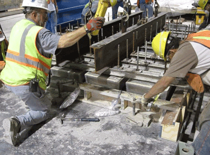
Figure 4: Placing the Voids
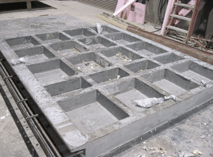
Figure 5: Formwork Removed
Figure 5 on page 5 shows the panel after the side forms and voids were removed. After the panels reached the required 14,000 psi release strength, they were moved from the casting area to the curing area. The panels were lifted into the vertical position, rotated 180 degrees and lowered back to the horizontal position in the proper orientation by the casting bed. This technique was used to reduce the handling stresses on the panels. Even though the concrete strength is very high at release, the sections where the panels are rotated from are very thin, limiting the amount of stress that can be taken without cracking. The critical section is at the very thin area where the toe of the transverse joint edge and the longitudinal rib intersect. By rotating the piece with the casting bed the issue of handling stresses is eliminated.
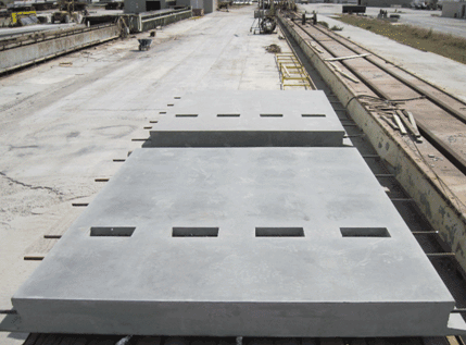
Figure 6: Completed Panels
After the pieces were cast, they were cured for 48 hours at 195 ?F as required by Lafarge for maximum strength and durability. Before the pieces were steam cured they measured approximately 15,000 psi compressive strength. A test cylinder was broken before the steam was turned off to verify that the panels had cured correctly, and the compressive strength of the UHPC at that time was 29,800 psi, exceeding the required design strength of 24,000 psi. After curing was complete, the panels were loaded on a truck and transported to ISU to be load tested.
Testing Equipment and Plant Modifications
Special equipment is required to produce the waffle slabs and to cast, cure, and test the UHPC. Products were purchased with the use of grant funds including formwork, quality control testing equipment, and UHPC placing and curing equipment. The equipment necessary to produce the UHPC waffle slabs is described in the sections below.
Formwork
No existing formwork matched the profiles of the waffle design or the edge conditions needed for the panel to panel joints. New formwork was designed to cast the slabs. At the time of the prototype casting, the final design was unknown because testing would be required to validate the design. By researching the typical bridge designs in the Iowa Highway system, it was determined that the maximum length would be 25 feet long. The slab design was far enough along at the time of prototype casting to determine that the width would be 8 feet. The casting bed was fabricated using this information and was utilized to rotate the prototype waffle slabs manufactured in Phase 1. The remaining form work for the demonstration project will be purchased once the panel design is completed.
Casting and Curing Equipment
Special equipment is necessary to mix, place, and cure UHPC. A concrete placing bucket built to match the width of the form was purchased in Phase 1. As mentioned previously, the bucket was needed to create the alignment of the steel fibers. The pieces were cured using propane heaters for the initial curing and a manually monitored steam curing setup was used to reach the final cured state. An automated electric bed heat system and steam curing system will be purchased in Phase 2.
Quality Control Equipment
Testing equipment is required to perform physical testing of fresh UHPC. This equipment was purchased before the prototype panel casting in September and included a flow table, vibrating table, molds for prisms and cylinders, and scales. Coreslab Structures personnel were trained on the equipment and related procedures.
Laboratory Load Testing
The prototype waffle slabs were shipped to the structures lab at ISU. A testing proposal was created by ISU, and it included testing the panels and the transverse joint in service, fatigue, and ultimate loading scenarios. Figure 7 below shows the test protocols. In order to more closely represent the field conditions of the Phase 2 bridge, it was determined that a prestressed concrete beam would need to be used as the support structure of the test setup. Fortunately one was available and donated by Coreslab Structures and shipped with the panels to ISU.
An UHPC joint casting was required and completed in the ISU structures lab with the help of Lafarge's technical representative. The transverse joint between the panels and the longitudinal area along the length of the support beams were cast with Ductal UHPC in the ISU Structures lab in late November 2009.
An FEA model of the completed test setup was created by ISU and several runs were made to locate the worst case loading scenarios before the physical testing began. This helped limit the amount of physical testing required as well as decrease the amount of time required for the testing phase of the project. The model closely represented the results of the physical tests, and will enable future projects incorporating UHPC to be designed and investigated more efficiently and with less physical testing.
| Test Number | Test Description | Location | Maximum Load |
|---|---|---|---|
| 1 | Service load test panel–2 | Center of the panel | 1.33a x 16kips = 21.3 kips |
| 2 | Service load test on transverse joint | Center of the joint | 1.75b x 16 kips = 28 kips |
| 3 | Fatigue test on the transverse Joint | Center of the joint | 28 kips ( 1 million cycles) |
| 4 | Ultimate load test of transverse joint | Center of the joint | 48 kips |
| 5 | Fatigue test on the panel-1 | Center of the panel | 21.3 kips ( 1 million cycles) |
| 6 | Ultimate load test of the panel | Center of the panel | 40 kips |
The results of the testing were promising. In summary, the 21.3 kip load placed on the panel caused two hairline cracks in the rib below the loading location, and the 28 kip load applied to the joint, caused a barely visible crack to form on the bottom of the joint as predicted by the FEA model. Fatigue loading applied for the specified 1,000,000 cycles, did not have any noticeable effect on the strength or durability of the panels.
Skid resistance of the driving surface was also tested. Seven commercially available form liners were ordered and samples of UHPC textures were cast and tested according to ASTM E303 standard method of testing skid resistance.
Additional information regarding the technical aspects of the testing and results is included in Appendix A. In general the panels performed very well and appear to be more than capable of holding up to the rigors of use on a public highway. Phase 1 was viewed as a success by all team members involved.
Work Scheduled for Phase Two
The work scheduled for Phase 2 of the project includes construction of the full scale demonstration bridge in Wapello County, a life cycle cost analysis, and a final detailed report concluding all the findings from both Phase 1 and Phase 2.
Demonstration Project
The demonstration bridge in Wapello County will be 33'-2" wide by 60'-0" long consisting of 14 UHPC slabs on conventional prestressed concrete girders. The slabs will be supported on 5 "B" Beam girders spaced at 7'-4" with 1'-11" overhangs. The panels will be jointed at the crown longitudinally with UHPC. UHPC will be also be used to fill the transverse joints. A preliminary bridge cross section is shown in Figure 8 below.
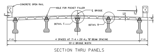
Figure 8: Cross Section of Demonstration Bridge
Wapello County will finalize the design of the demonstration bridge approaches and layout, and Iowa DOT will finalize the design of the demonstration bridge and deck panels in early April 2010. The letting is tentatively scheduled for early July 2010, with construction starting shortly after. Panel production should begin in June and will be completed in time to meet the proposed construction schedule.
Plant Modifications
Plant modifications to accommodate the casting of the demonstration project waffle slabs will take place during the months of April through June 2010. These modifications include the installation of a fiber addition system to the mixer, the purchase of the remaining formwork necessary to cast the panels, installation of a bed heat system to efficiently cure the fresh UHPC, construction and installation of a steam curing system and chamber, and the purchase of equipment that eliminates the need for handling devices in the wearing surface of the bridge.
In-Situ Testing and Evaluation
A specific instrumentation plan will be developed to evaluate the structural performance of the bridge and specifically the waffle slab component, using strain, deflection and acceleration sensors. It is anticipated that the instrumentation plan will enable the evaluation of at least the following structural characteristics:
- Deck strain / stress levels and load distribution
- Overall superstructure live load transverse distribution and strain / stress levels
- Overall bridge superstructure deflections
- Bridge end member restraint
- Edge stiffening
- Dynamic amplification factor
After the bridge construction is completed, the instrumentation plan noted above will be used during the performance of a live load test to evaluate the structural performance of the bridge. This testing will provide insight into the validity of the bridge design assumptions and identify any potential undesirable serviceability behavior. A second similar load test will be performed after the bridge has been in service for approximately three months to determine any potential changes in service behavior. A visual inspection will also be performed prior to each load test.
The testing will be conducted with controlled live loads at service level using a typically loaded standard truck. A series of different transverse static load positions will be used to create worst case loading conditions in the waffle slab and the bridge. A series of dynamic tests will also be conducted to provide some quantification of bridge dynamic performance.
A final report will be completed detailing the Phase 2 production processes and the findings from the in-situ testing. In addition to the Phase 2 report, a detailed life cycle cost analysis (LCCA) will be created to display the cost savings and feasibility of the full depth UHPC waffle deck system for use in future projects. Included in the LCCA will be a discussion of the costs of first deployments of the technology where fabrication facility construction costs will be included and repeat project costs where the fabrication facility costs will be removed. Also, design recommendations and production standards will be outlined in a separate document.
The Phase 2 report, design standards, and LCCA will help make the full depth UHPC bridge deck system a marketable and widely used construction system. This will provide the FHWA and departments of transportation a solution that will help extend the useful life of North America's bridges and highway system.
References
- U.S. Department of Transportation- NTIS Accession No. PB2007-112112 (2007). "Analysis of an Ultra-High Performance Concrete Two–Way Ribbed Bridge Deck Slab"
- Toutlemonde, F, Lauvin, L, and Renaud, J. (2007). "Fatigue Performance of an UHPFRC Ribbed Slab Applied as a Road Bridge Deck Verified According to the Eurocodes"
- Toutlemonde, F, Lauvin, L, Renaud, J.-C, Brisard, S, and Resplendino, J. "Local Bending Tests & Punching Failure of a Ribbed UHPFRC Bridge Deck"
- Perry, V. (2007). "Innovative Field Cast UHPC Joints for Precast Deck Panel Bridge Superstructures – CN Overhead Bridge at Rainy Lake, Ontario"

