The Implementation of Full Depth UHCP Waffle Bridge Deck Panels
APPENDIX A: WAFFLE DECK PANEL FABRICATION
Prototype Bridge
A full–scale single–span, two–lane, prototype, full–depth bridge system was designed as a replacement of an existing bridge in Wapello County, Iowa, and the details of this structure are shown in Figure 1. The prototype bridge is 33 ft wide and 60 ft long and it consisted of prefabricated, full–depth, precast concrete panels installed on five standard Iowa "B" girders placed at a center–to–center distance of 7ft 4 inches.
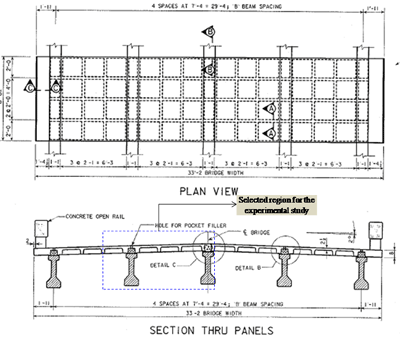
Figure 1: Plan and cross section details of the proposed UHPC Waffle Deck Bridge in Wapello County.
The waffle deck is expected to be made fully composite with girders using the following connections:
- Shear pocket connection: This connection is formed between the girder and the waffle deck using shear pockets. In this connection, the shear pockets in the waffle deck are filled with UHPC and a shear hook extended from the girder is embedded into the UHPC fill (see Figure 2). This will cause the girders and the waffle deck to act in a composite manner.
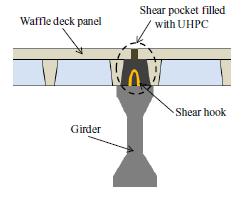
Figure 2: Shear pocket connection details between girder and the waffle deck
- Waffle panel to girder longitudinal connection: This connection is formed between the central girder and the waffle deck. In this connection, the dowel bars from the panels and the shear hook from the girder are tied together with additional reinforcement along the girder length and the gap between the panels is filled with UHPC (see Figure 3). This connection will provide a positive moment connection between the girder and the panels.
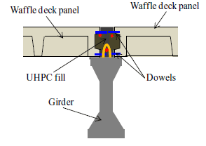
Figure 3: Connection details between the central girder and the waffle deck
The bridge consisted of waffle deck panels which were 16 ft wide (full width) and 8 in. thick. They are connected across the length of the bridge using a transverse joint connection shown in Figure 4. In this connection, the dowel bars from the panels are tied together with additional transverse reinforcement and the gap between the panels is filled with UHPC (see Figure 4). This connection will provide continuity between the panels and facilitate load transfer between the panels.
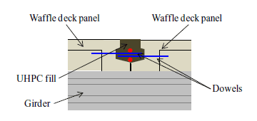
Figure 4: Connection details between the waffle deck panels
Panel Details and Prefabrication
The UHPC waffle panels were designed with conventional mild steel reinforcement primarily to resist the transverse flexural moments (i.e., for moments induced about the bridge longitudinal axis) in accordance with the current AASHTO slab deck design provisions (AASHTO, 2007). This resulted in Grade 60 No. 7 (db = 0.875 in, where db is diameter of the bar) and No.6 (db = 0.75 in.) mild steel reinforcement located at 1¼ inches from the bottom surface and at 1 5/8 inches from the top surface of the panel, respectively. In the longitudinal direction, the panels were detailed with Grade 60, No. 7 and No.6 mild steel reinforcement at 2 1/8 inches from the bottom surface and at 2 3/8 inches from the top surface, respectively. All the reinforcement was provided along panel ribs in both directions. Figure 5 shows the cross–section and reinforcement details of a typical waffle deck panel designed for the prototype bridge.
For the experimental investigation, a waffle deck region between two adjacent girders as identified in Figure 1 was chosen. Accordingly, two waffle deck panels with dimensions of 8 ft (length) by 9 ft 9 in. (width) were fabricated by Coreslab Structures (Omaha) Inc. in September 2009. Commercially available standard Ductal® mix was used as the UHPC mix design.
The UHPC waffle panels were designed with conventional mild steel reinforcement primarily to resist the transverse flexural moments (i.e., for moments induced about the bridge longitudinal axis) in accordance with the current AASHTO slab deck design provisions (AASHTO, 2007). This resulted in Grade 60 No. 7 (db = 0.875 in, where db is diameter of the bar) and No.6 (db = 0.75 in.) mild steel reinforcement located at 1¼ inches from the bottom surface and at 1 5/8 inches from the top surface of the panel, respectively. In the longitudinal direction, the panels were detailed with Grade 60, No. 7 and No.6 mild steel reinforcement at 2 1/8 inches from the bottom surface and at 2 3/8 inches from the top surface, respectively. All the reinforcement was provided along panel ribs in both directions. Figure 5 shows the cross–section and reinforcement details of a typical waffle deck panel designed for the prototype bridge. For the experimental investigation, a waffle deck region between two adjacent girders as identified in Figure 1 was chosen. Accordingly, two waffle deck panels with dimensions of 8 ft (length) by 9 ft 9 in. (width) were fabricated by Coreslab Structures (Omaha) Inc. in September 2009. Commercially available standard Ductal® mix was used as the UHPC mix design.
| Traffic Occurring During Total Roadway Closure Hours | Traffic Normally Occurring During Those Hours | ||
|---|---|---|---|
| Time (hours) | Strength (psi) | Time (hours) | Strength (psi) |
| 22 | 1800 | 20 | 850 |
| 24 | 4500 | 26 | 5000 |
| 26 | 6250 | 44 | 10650 |
| 44 | 11650 | 52 | 13800 |
| 52 | 13400 | – | – |
| 28 days (post–steam cure strength) | 21843 | 28 days | 22120 |
After curing, the panels were transported to the Iowa State University's (ISU) Structures Laboratory. Both the deck panels exhibited a very smooth surface on all sides that were in contact with the formwork. Other surfaces, especially the underside of the panels appeared somewhat rough.
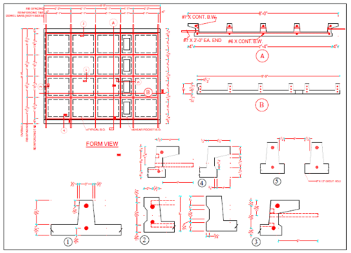
Figure 5: Reinforcement details of the UHPC waffle deck test panels
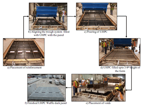
Figure 6: Construction sequence of the UHPC Waffle deck panel at the precast plant.

