U.S. Department of Transportation
Federal Highway Administration
1200 New Jersey Avenue, SE
Washington, DC 20590
202-366-4000
Federal Highway Administration Research and Technology
Coordinating, Developing, and Delivering Highway Transportation Innovations
 |
| This report is an archived publication and may contain dated technical, contact, and link information |
|
Publication Number:
FHWA-HRT-04-107
|
Previous | Table of Contents | Next
Piles are mainly used to support structures under lateral and vertical loads. Vertical load-bearing capacity of piles depends mainly on site conditions, soil properties, pile material properties, pile dimensions, and method of pile installation. Pile types can be divided into two categories, according to their method of installation.(3) The first category consists of driven piles, which displace and disturb the soil, and the second category consists of piles that are installed without soil displacement. Steel, precast concrete, wood, and fiber-reinforced polymer piles belong to the first category. In the second category, soil is removed by drilling, and concrete is cast in the borehole to form the pile.
Analytical methods(4) and several design codes(5,6,7) can be used to evaluate the axial pile capacity, end bearing, and shaft friction along the pile. Dynamic methods, based on pile driving measurements, can be used to predict the axial static capacity of driven piles and assess the drivability and durability of piles during installation.(8) However, before dynamic testing is conducted, several material properties and data must be determined; these include the pile length, cross-sectional area, specific weight, wave speed, and dynamic elastic modulus. The evaluation of the dynamic methods for predicting the load-set response and the ultimate static capacity of piles must be obtained by comparing the dynamic method analysis results and static load test (SLT) results. Considering the engineering use of fiber-reinforced composite piles, it is essential to perform the above-mentioned engineering testing procedure to evaluate the behavior of these piles under axial loads and to develop reliable design methods to assess the short- and long-term behavior of fiber reinforced polymer (FRP) composite piles.
In 1998, a waterfront rehabilitation project known as the Hudson River Park began. One goal was the replacement of up to 100,000 bearing piles for lightweight structures. The corrosion of steel, deterioration of concrete, and vulnerability of timber piles to the marine environment led the developer to consider composite materials with high degradation resistance, such as FRPs, as a replacement for pilings made of timber, concrete, or steel.
Concurrently, in 1998, the Federal Highway Administration (FHWA), with a long-term interest in the application of polymers in infrastructure, initiated a research project on the use of FRP pilings,
The main purpose of this current research was to address the need for a feasibility assessment of FRP composite bearing piles for highway and related facilities substructures, replacing traditional materials such as timber, concrete, or steel, specifically in the construction of waterfront structures in hostile marine environments. The engineering application of FRP may present competitive alternatives to conventional pile materials, due to the accelerated degradation of these conventional materials in aggressive environments (figures 1 and 2). Further, chemical treatment of wood pilings has become more difficult, due to the toxic nature of typical chemical treatments. State departments of transportation (DOT) facing major rehabilitation projects also have become interested in assessing the feasibility of using FRP composite bearing piles for infrastructure applications. To assess the feasibility of using FRP composite piles as vertical load-bearing piles, laboratory tests and a full-scale experiment, including dynamic and static load tests on FRP piles were conducted.
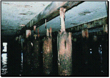
Figure 1. Photo. Marine borers (Limnoria) attacking untreated timber piles that support many of New York's highways and harbor piers.(9)
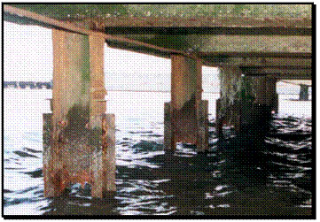
Figure 2. Photo. Complete corrosion of steel H piles supporting a harbor pier
(recently installed retrofit channels are already corroding).(9)
Research on the engineering behavior of FRP piles has primarily been focused on these piles' performance under lateral loading as fender piles. In general, current research and applications of FRP piles have addressed:
The research conducted thus far has involved primarily laboratory tests on the mechanical behavior, flexural behavior, and buckling resistance of FRP pile materials.
Laboratory tests were performed on the Plastic Piling, Inc. (PPI), pile to determine the lateral flexural stiffness. The tested pile had a 38.7-centimeter (cm)- (15.25-inch-) diameter, and the steel reinforcement consisted of 16 25.4-millimeter (mm)- (1-inch-) diameter bars connected with a spiral. The free span between the two supports at both pile ends was 5.8 meters (m) (19 feet (ft)). During the testing, the load was applied cyclically at the middle of the free span. The test results show that loads exceeding 222 kilonewtons (kN) (50 kips) caused permanent deflections in the pile. At these loads, yielding of the steel bars was initiated, inducing slippage in the recycled plastic. The ultimate lateral load-bearing capacity was 311 kN (70 kips), at which point the pile underwent fully plastic behavior. Further, the pile's response was ductile up to this load, and the recycled plastic did not appear to crack during loading.
Two axial laboratory tests were performed to obtain the buckling loads of Lancaster Composite, Inc., piles.(10) The pile samples had diameters of 25.4 and 30.5 cm (10 and 12 inches) and lengths of 9 and 11 m (29.52 and 36.08 ft), respectively. Two loading cycles were applied to the 30.5-cm- (12-inch-) diameter pile sample to a maximum load of 2113 kN (475 kips) and 2228 kN (501 kips); the latter load caused the sample to experience failure. A third applied loading cycle caused this pile sample to buckle at 1841 kN (414 kips). The maximum applied load on the 25.4-cm- (10-inch-) diameter pile sample at which it experienced failure was 1392 kN (313 kips).
Reviewing the current state-of-practice within the framework of the current research with the manufacturers of the selected FRP piles illustrated the need for both laboratory and field axial loading tests to assess the engineering performance of these piles as axial load-bearing piles.
The current state-of-practice related to the engineering use of FRP piles(9,11) indicates that FRP composite piles primarily have been used experimentally for fender piles, waterfront barriers, and bearing piles for light structures.(12-13)
Figure 3 shows fender piles manufactured by Lancaster Composite, Inc., in the U.S. Naval Submarine Base, San Diego, CA. Pier 5000, located in Point Loma at the southern tip of the San Diego Bay, is one of four major piers that serve as home base for several attack submarines.(14)
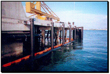
Figure 3. Photo. Fender piles in the U.S. Naval Submarine Base, San Diego, CA.
Figure 4 shows fender piles manufactured by PPI in U.S. Navy Pier 10 in San Diego, CA. This pier berths U.S. Navy vessels.
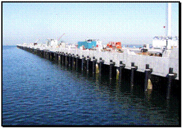
Figure 4. Photo. Fendering system in the U.S. Navy Pier 10, San Diego, CA.
Figure 5 shows the Nashville Avenue Marine Terminal at Port of New Orleans, LA. This terminal contains 40.6-cm (16-inch) SEAPILE® piles and a 30.5- by 30.5-cm (12- by 12-inch) SEATIMBER® fendering system that was manufactured by Seaward International in 1996.

Figure 5. Photo. Fendering system, Nashville Avenue Marine Terminal, Port of New Orleans, LA.
Figure 6 shows a floating dock project that consists of piles manufactured by American Ecoboard. The piles are 30.5 cm (12 inches) in diameter and 13.7 m (45 ft) long.
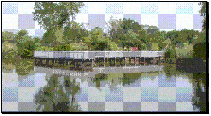
Figure 6. Photo. Floating dock project.
The current practice illustrates the lack of mechanical laboratory test results that would help assess engineering behavior of the FRP composite materials under axial loading, as well as the lack of SLT results and comparisons with dynamic experimental test results. The engineering applications of the FRP composite piles as bearing piles raise the following research and development (R&D) needs.
The engineering use of FRP bearing piles requires assessing their field performance, as well as developing and evaluating reliable testing procedures and design methods to assess:
To address these R&D needs and assess the feasibility of using FRP composite piles as vertical load-bearing piles, a full-scale experiment including dynamic and static load tests on FRP piles was conducted at a site provided by the Port Authority of New York and New Jersey (PANY&NJ) at their Port of Elizabeth facility in New Jersey. Figure 7 shows the Port of Elizabeth demonstration site. The full-scale experiment was conducted with the cooperation and support of the PANY&NJ engineering department and the New York State Department of Transportation (NYSDOT).
Figure 7. Photo. Port of Elizabeth demonstration site.
The scope of this demonstration project included:
To select the piles for this demonstration project, a team of experts prepared a request for qualification and disseminated the request to composite piling manufacturers; these manufacturers were invited to submit their qualifications and products for consideration. The items in the request for qualifications were: contact information, general description of piling system, material properties, drivability, durability, creep, quality assurance/quality control, experience, field records, and specimens. The selected FRP composite piles consisted of recycled plastic reinforced by fiberglass rebar (SEAPILE composite marine piles), recycled plastic reinforced by steel bars, recycled plastic with no reinforcement rebar, recycled plastic with randomly distributed fiberglass fibers (Trimax), and concrete-filled plastic shell manufactured, respectively, by Seaward International Inc., PPI, American Ecoboard, U.S. Plastic Lumber (USPL), and Lancaster Composite, Inc. Figure 8 indicates the locations of the pile
Figure 8. Illustration. Locations of pile manufacturers.
Pile instrumentation was performed at the manufacturing plants and included installing strain gauges at several levels in the piles. The manufacturers delivered these piles to the site, and the installation of the piles was conducted with the full support and cooperation of the manufacturers. All the manufacturers also attended the SLTs.
This research report summarizes the results of this full-scale experiment and the companion laboratory tests.
Chapter 2 presents an engineering analysis approach for establishing the equivalent mechanical properties of the composite material, including elastic modulus for the initial loading quasilinear phase, axial compression strength, inertia moment, and critical buckling load. The composite material used in this study consisted of recycled plastic reinforced by fiberglass rebar (SEAPILE composite marine piles), recycled plastic reinforced by steel bars, and recycled plastic reinforced with randomly distributed fiberglass (Trimax), manufactured by Seaward International Inc., PPI, and USPL, respectively.
Chapter 3 describes the results of the SLTs, along with the instrumentation schemes that were specifically designed for strain measurements in the FRP piles. The experimental results are compared with current design codes and with the methods commonly used for evaluating the ultimate capacity, end bearing capacity, and shaft frictional resistance along the piles. This engineering analysis leads to preliminary recommendations for the design of FRP piles.
In chapter 4, Pile Driving Analyzer® (PDA) and Pile Integrity Tester (PIT) test results were analyzed using the Case Pile Wave Analysis Program (CAPWAP)(1) and the GRL Wave Equation Analysis of Piles program (GRLWEAP)(2) to establish the dynamic properties of the FRP piles. The PDA also was used to evaluate the feasibility of installing FRP piles using standard pile driving equipment. Pile bearing capacities were assessed using the CAPWAP program with the dynamic data measured by the PDA, and the calculated pile capacities were compared with the results of SLTs performed on the four FRP piles.
Chapter 5 summarizes the main conclusions and recommendations of this project.

