U.S. Department of Transportation
Federal Highway Administration
1200 New Jersey Avenue, SE
Washington, DC 20590
202-366-4000
Federal Highway Administration Research and Technology
Coordinating, Developing, and Delivering Highway Transportation Innovations
 |
| This report is an archived publication and may contain dated technical, contact, and link information |
|
Publication Number: FHWA-RD-03-083 Date: June 2003 |
This chapter presents results of pier- and abutment-scour experiments to study effects of clay content on clear-water scour. Results show that the presence of even a small amount of cohesive material may reduce scour considerably. To quantify the impact of clay content, scour in clayey sands is expressed as a fraction of scour measured in noncohesive materials through a clay content reduction factor, Kcc. It is shown that Kcc is a function of clay content. It is also shown that different clay minerals have varying impacts on reducing bridge scour.
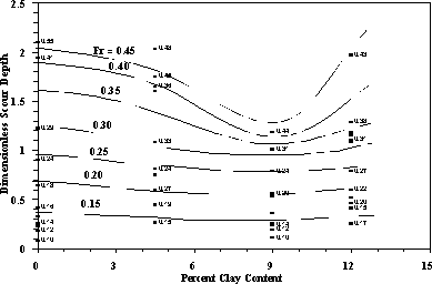
Scour at bridges has been studied extensively in the past for noncohesive sediments. The currently adopted scour estimation methodologies were basically developed from laboratory experiments conducted in sand or gravel beds. No method for scour depth estimation is available to account for the presence of cohesive materials in cases where bridges are founded in clayey sands. Figure 30 illustrates the effect of varying cohesive material content on abutment scour. As shown in this figure, as the cohesive material content is increased, the depth of scour is reduced. However, beyond a certain threshold this behavior is reversed. The ultimate scour depth computations for the sandy clay material described above is further complicated by the presence of different clay minerals. This chapter presents the results of the experimental study conducted at the CSU to account for the presence of clay on the resulting ultimate scour.

Figure 30. Effect of clay content on abutment scour.
Bridge scour experiments presented in this section are classified as pier scour and abutment scour experiments. In each category of experiments, series of runs utilizing different flumes were conducted by varying the clay content under different flow conditions. Additionally, in the abutment scour experiments, the effects of clay mineralogy were studied. Details of the experiments are presented in various publications (21, 22, 4, and 5).
Flumes
Experiments were conducted in three different test flumes housed at the Engineering Research Center Hydraulics Laboratory at CSU. These flumes were identified as the river mechanics flume, sediment transport flume, and the steep flume. The river mechanics flume is 5 m wide by 30 m long, the sediment transport flume is 2.4 m wide by 60 m long, and the steep flume is 1.2 m wide by 12 m long. The flow depths in the experiments varied between 0.12 m and 0.3 m, and the corresponding approach Froude numbers ranged from 0.1 to 0.8.
Measurements
Results of experiments were quantified through velocity, depth of flow, and depth of scour measurements. For velocity measurements, one- and two-dimensional magnetic flow-meters were utilized. In each experiment, approach velocity to each pier/abutment was determined by depth- and width-integrated average of seven vertical profiles, each with a minimum of 10 measurements. Similarly, the approach depth was a width- and length-averaged value of seven water surface elevation measurements. The bed elevations were measured along the test flumes before and after each experiment. The depth of scour was measured during and at the end of each experiment; it was determined by the difference between the measured minimum bottom elevation at the nose of a pier/abutment and the maximum elevation away from the structure. The accuracy of velocity measurements were within 5 percent, and scour depth measurements were within 3 percent.
Sediments
The sand used in mixing with clayey soils had a median diameter of 0.55 mm and a gradation coefficient  g of 2.43. In the pier scour experiments, Montmorillonite mineral clay was used in preparing the clayey sand mixtures. In the abutment scour experiments, both Montmorillonite and Kaolinite clays were utilized to study the effects due to the type of clay mineral present in mixtures.
Piers and Abutments
To isolate the effects due to the clay content, all variables other than flow velocity and clay content were kept constant. In all of the pier scour experiments, circular piers of 0.15 m diameter were used with a relatively constant approach depth of 0.24 m. In abutment scour experiments, rectangular vertical-wall abutments with protrusion lengths of 0.20 m were used with an approach depth of 0.24 m. In the Kaolinite-clay experiments, geometrically similar 0.10-m abutments were used with 0.12-m flow depths.
Tables 23 and 24 present the experimental conditions as well as the resulting scour depths for the pier and abutment experiments, respectively. Pier scour experiments identified as runs MH 13-1 through MH 22-3 in table 23 were conducted in the 5-m wide flume, and runs MH30-1 through MH 32-3 were conducted in the 2.4-m wide flume. In these experiments sand-clay mixtures were prepared utilizing Montmorillonite clay soil. In addition to the measured depth of scour values, table 23 also presents scour hole volumes for each experiment. The pier diameter used in these experiments was 0.15 m.
Table 23. Summary of pier scour experiments in clayey sands.
|
Run ID |
Clay Content CC (%) |
Approach Froude No. Fr |
Depth of Scour Dsc (m) |
Dimensionless Scour Dsc/b |
|---|---|---|---|---|
| (1) | (2) | (3) | (4) | (5) |
| MH 13-1 | 0.0 | 0.184 | 0.088 | 0.58 |
| MH 13-2 | 1.6 | 0.198 | 0.076 | 0.50 |
| MH 13-3 | 3.2 | 0.204 | 0.092 | 0.61 |
| MH 14-1 | 0.0 | 0.176 | 0.069 | 0.46 |
| MH 14-2 | 1.6 | 0.196 | 0.077 | 0.50 |
| MH 14-3 | 3.2 | 0.189 | 0.066 | 0.43 |
| MH 15-1 | 0.0 | 0.185 | 0.089 | 0.58 |
| MH 15-2 | 1.6 | 0.207 | 0.105 | 0.69 |
| MH 15-3 | 3.2 | 0.211 | 0.091 | 0.60 |
| MH 16-1 | 0.0 | 0.205 | 0.116 | 0.76 |
| MH 16-2 | 1.6 | 0.230 | 0.127 | 0.83 |
| MH 16-3 | 3.2 | 0.244 | 0.144 | 0.94 |
| MH 17-1 | 6.4 | 0.176 | 0.045 | 0.30 |
| MH 17-2 | 9.6 | 0.196 | 0.052 | 0.34 |
| MH 17-3 | 12.8 | 0.189 | 0.051 | 0.34 |
| MH 18-1 | 6.4 | 0.185 | 0.058 | 0.38 |
| MH 18-2 | 9.6 | 0.207 | 0.057 | 0.37 |
| MH 18-3 | 12.8 | 0.211 | 0.060 | 0.39 |
| MH 19-1 | 6.4 | 0.212 | 0.066 | 0.44 |
| MH 19-2 | 9.6 | 0.232 | 0.096 | 0.63 |
| MH 19-3 | 12.8 | 0.235 | 0.084 | 0.55 |
| MH 20-1 | 6.4 | 0.212 | 0.079 | 0.52 |
| MH 20-2 | 9.6 | 0.231 | 0.105 | 0.69 |
| MH 20-3 | 12.8 | 0.232 | 0.096 | 0.63 |
| MH 21-1 | 6.4 | 0.185 | 0.058 | 0.38 |
| MH 21-2 | 1.6 | 0.207 | 0.105 | 0.69 |
| MH 21-3 | 3.2 | 0.211 | 0.092 | 0.60 |
| MH 22-1 | 6.4 | 0.180 | 0.054 | 0.35 |
| MH 22-2 | 1.6 | 0.195 | 0.077 | 0.50 |
| MH 22-3 | 3.2 | 0.188 | 0.068 | 0.44 |
| MH 30-1 | 0.0 | 0.307 | 0.248 | 1.63 |
| MH 30-2 | 6.4 | 0.317 | 0.158 | 1.04 |
| MH 30-3 | 12.8 | 0.329 | 0.094 | 0.62 |
| MH 31-1 | 3.2 | 0.307 | 0.210 | 1.38 |
| MH 31-2 | 9.6 | 0.310 | 0.166 | 1.09 |
| MH 31-3 | 12.8 | 0.329 | 0.135 | 0.88 |
| MH 32-1 | 0.0 | 0.232 | 0.191 | 1.25 |
| MH 32-2 | 6.4 | 0.227 | 0.122 | 0.80 |
| MH 32-3 | 12.8 | 0.228 | 0.089 | 0.58 |
Table 24. Summary of abutment scour experiments in clayey sands.
| Run ID (1) |
Clay Content CC (%) (2) |
Scour Depth Dsc (m) (3) |
Normalized Scour Depth Dsc/Ds (4) |
Scour Hole Width W (m) (5) |
Side Slope of Scour Hole 2 (degrees) (6) |
Type of Clay Mineral (7) |
|---|---|---|---|---|---|---|
| NY 81-A | 0.0 | 0.253 | 1.00 | 0.399 | 32 | Montmorillonite |
| NY 82-A | 0.0 | 0.158 | 1.00 | 0.293 | 28 | Montmorillonite |
| NY 83-A | 0.0 | 0.113 | 1.00 | 0.241 | 25 | Montmorillonite |
| NY 84-B | 0.0 | 0.274 | 1.00 | 0.402 | 34 | Montmorillonite |
| NY 81-B | 4.5 | 0.210 | 0.88 | 0.439 | 26 | Montmorillonite |
| NY 82-B | 4.5 | 0.104 | 0.81 | 0.259 | 22 | Montmorillonite |
| NY 83-B | 4.5 | 0.094 | 1.21 | 0.189 | 27 | Montmorillonite |
| NY 84-B | 4.5 | 0.262 | 1.01 | 0.418 | 32 | Montmorillonite |
| NY 81-C | 9.0 | 0.131 | 0.74 | 0.247 | 28 | Montmorillonite |
| NY 82-C | 9.0 | 0.073 | 0.68 | 0.128 | 30 | Montmorillonite |
| NY 83-C | 9.0 | 0.067 | 1.08 | 0.128 | 28 | Montmorillonite |
| NY 84-C | 9.0 | 0.152 | 0.60 | 0.326 | 25 | Montmorillonite |
| NY 81-D | 12.0 | 0.140 | 0.84 | 0.265 | 28 | Montmorillonite |
| NY 82-D | 12.0 | 0.067 | 0.75 | 0.107 | 32 | Montmorillonite |
| NY 83-D | 12.0 | 0.052 | 1.15 | 0.107 | 26 | Montmorillonite |
| NY 84-D | 12.0 | 0.165 | 0.74 | 0.369 | 24 | Montmorillonite |
| NY 81-A | 0.0 | 0.253 | 1.00 | 0.399 | 32 | Kaolinite |
| NY 84-A | 0.0 | 0.274 | 1.00 | 0.402 | 34 | Kaolinite |
| NY 78-A | 10.0 | 0.229 | 0.83 | 0.384 | 31 | Kaolinite |
| NY 79-A | 10.0 | 0.256 | 0.92 | 0.399 | 33 | Kaolinite |
| NY 79-B | 20.0 | 0.052 | 0.19 | 0.040 | 52 | Kaolinite |
| NY 80-B | 20.0 | 0.152 | 0.53 | 0.207 | 36 | Kaolinite |
| NY 77-B | 20.0 | 0.012 | 0.21 | 0.015 | 39 | Kaolinite |
| NY 72-A | 30.0 | 0.030 | 0.10 | 0.226 | 8 | Kaolinite |
| NY 71-B | 30.0 | 0.000 | 0.00 | 0.000 | 0 | Kaolinite |
| NY 80-C | 50.0 | 0.226 | 0.77 | 0.369 | 31 | Kaolinite |
| NY 77-C | 50.0 | 0.094 | 2.30 | 0.326 | 16 | Kaolinite |
Pier Scour
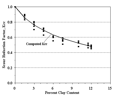
Results of pier scour experiments in clayey sands are presented in figure 31. In deriving this figure scour, depths observed in Montmorillonitic clayey sand were normalized with the sand scour observed under similar flow and geometry conditions. In figure 31, pier scour results are expressed in terms of a reduction factor Kcc whose value ranges between 0 and 1; Kcc equal to unity denotes the depth scour being equal to that observed in sand. Since the pier shape and width, flow depth, and sand properties were kept near constant, it was possible to identify the effects of clay content under various flow conditions. Figure 31 shows that for a given clay content, the clay content reduction factor (Kcc) is independent of approach flow conditions.
The expression that best fits the data is given by (23):
 |
(27)
|

Figure 31. Pier scour reduction factor for Montmorillonite clay mixtures.

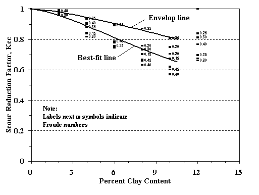
Figure 32. Abutment scour reduction factor for Montmorillonite clay mixtures.
Abutment Scour
Results of abutment experiments in clayey sands are summarized in figures 32 and 33. Similar to pier scour experiments; in deriving these figures, scour depths observed in clayey sand were normalized with the scour observed in sand under similar flow and geometry conditions. In figures 32 and 33, abutment scour results are expressed in terms of a reduction factor, Kcc, whose value ranges between 0 and 1; Kcc equal to unity denotes the depth of scour being equal to that observed in sand. Since the abutment size and shape, flow depth, and sand properties were kept near constant, it was possible to identify the effects of clay content under various flow conditions. Figures 32 and 33 show that for a given clay content, the clay content reduction factor (Kcc) is independent of approach flow conditions. The expression that best fits the data for Montmorillonite clay mixtures is given by:
 |
(28)
|
a, b = 16 and 1.5 for the best-fit line; and 22 and 1.8 for the envelop line that can be used as a design equation, respectively.

Figure 33. Abutment scour reduction factor for Kaolinite clay mixtures.
For the Kaolinite clay mixtures the expression that best fits the data is:
 |
(29)
|
where a,b = 16 and 3.8 for the best-fit line and 20 and 4.5 for the envelop line, respectively.
Bed material mixtures that are predominately sand with low clay content can be analyzed using the traditional non cohesive soil parameters for scour with a reduction factor to account for the cohesive effects from the clay fraction. The reduction coefficients found in these experiments are given by equations 28 and 29 above for Montmorillonite and Kaolinite clays, respectively. Two sets of coefficients are given for equations 28 and 29 to represent the best-fit line through the data and the envelop-line that can be used as a design equation. Bed material mixtures with high clay contents are governed by clay properties that are the subject of the next chapter. There is no clear clay content percentage that determines where the shift occurs from noncohesive to clay properties. For the present study this limit was found to be around 12 percent and was affected by the clay mineralogy.