U.S. Department of Transportation
Federal Highway Administration
1200 New Jersey Avenue, SE
Washington, DC 20590
202-366-4000
Federal Highway Administration Research and Technology
Coordinating, Developing, and Delivering Highway Transportation Innovations
 |
| This report is an archived publication and may contain dated technical, contact, and link information |
|
Publication Number: FHWA-HRT-06-133 Date: March 2007 |
Alkali-aggregate reaction (AAR) is a reaction in concrete between the alkali hydroxides, which originate mainly from the portland cement, and certain types of aggregate. Two types of AAR are currently recognized; these are alkali-silica reaction (ASR) and alkali-carbonate reaction (ACR). As the names imply, these types of reaction differ in that they involve reactions with either siliceous or carbonate phases in the aggregates (table 3). ASR is far more widespread than ACR and is the focus of this document. ACR will not be discussed further, however, it should be noted that the measures used to control ASR have generally shown limited effectiveness in controlling ACR.
Table 3. Terminology for alkali-aggregate reactions (CSA A23.1-04).
| Alkali-Aggregate Reaction AAR) | Chemical reaction in either concrete or mortar between hydroxyl ions (OH−) of the alkalies (sodium and potassium) from hydraulic cement or other sources and certain constituents of some aggregates; under certain conditions deleterious expansion of concrete or mortar may result. |
|---|---|
| Alkali-Carbonate Reaction (ACR) | Chemical reaction in either concrete or mortar between hydroxyl ions (OH−) of the alkalies (sodium and potassium) from hydraulic cement or other sources and certain carbonate rocks, particularly calcitic dolostone and dolomitic limestones, present in some aggregates; the reaction causes dedolomitization and expansion of the affected aggregate particles, leading to abnormal expansion and cracking of concrete in service. |
| Alkali-Silica Reaction (ASR) | Chemical reaction in either concrete or mortar between hydroxyl ions (OH−) of the alkalies (sodium and potassium) from hydraulic cement or other sources and certain siliceous rocks and minerals, such as opal, chert, microcrystalline quartz, and acidic volcanic glass, present in some aggregates. This reaction and the development of the alkali-silica gel reaction product can, under certain circumstances, lead to abnormal expansion and cracking of the concrete. |
Concrete is a porous material (typically about 10 percent of the volume of concrete is occupied (by pores) and, in saturated concrete, the pores contain a solution composed of alkali hydroxides (NaOH and KOH). The origin of the sodium (Na) and potassium (K) is, principally, the portland cement. Table 4 shows an oxide analysis of a typical portland cement.
Table 4. Typical chemical analysis for portland cement.
| Oxide | SiO2 |
Al2O3 |
Fe2O3 |
CaO |
MgO |
Na2O |
K2O |
SO3 |
LOI |
|---|---|---|---|---|---|---|---|---|---|
| Percent | 20.55 |
5.07 |
3.10 |
64.51 |
1.53 |
0.15 |
0.73 |
2.53 |
1.58 |
It is convenient to convert the potassium oxide to an equivalent amount of sodium oxide using a molar ratio and to express the alkalies in terms of the equivalent alkali content of the cement; which is defined as:
Equivalent Alkalies, Na2Oe = Na2O + 0.658 x K2O (1)
For the analysis given in table 4, the equivalent alkali content is calculated as follows:
Na2Oe = 0.15 + 0.658 x 0.73 = 0.63% (2)
The equivalent alkali content of portland cements produced in or imported into North America typically ranges from 0.20 to 1.20 percent Na2Oe.
Although the alkalies represent a small fraction of the portland cement, they dominate the pore solution of the concrete, which, as a result, is highly alkaline with a pH in the range of 13.2 to 13.8. Diamond (1989) indeed found a direct correlation between the cement alkali content and the pH of the pore solution.
Figure 6 summarizes the sequence of ASR in concrete. Some forms of silica (SiO2) found in some aggregates are unstable at high pH and react with the alkali hydroxides to form an alkali-silica gel. This gel has the propensity to absorb large quantities of water and swell. Under certain conditions, the swelling pressures can cause expansion and, eventually, cracking of the concrete.
Figure 6 demonstrates the sequence of alkali-silica reaction (ASR) in concrete.
Figure 6. Sequence of alkali-silica reaction (ASR) in concrete.
Not all forms of silica are reactive in concrete. The reactivity depends on the crystal structure of the silica rather than its chemical composition. For example both quartz and opal are silica minerals and are predominantly composed of silica (SiO2); i.e., they are of similar composition (although opal has varying proportion of water, usually 3 to 9 percent). Quartz has a well-ordered crystal structure (figure 7) and is very stable in concrete at normal temperatures. Opal, on the other hand, has an internal structure consisting of more-or-less densely packed aggregate of spheres of silica (cristobalite and/or tridymite) and is highly reactive in concrete.
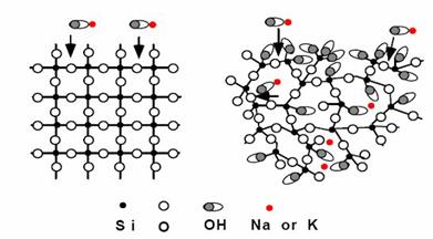
Figure 7. Schematic showing difference in crystal structure of quartz (left) and opal (right).
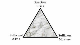
Table 5 contains a list of reactive silica forms and the rock types in which they may be found. Not all sources of these rock types are reactive in concrete. Damaging reaction will only occur if these rock types contain sufficient quantities of the reactive silica. For example, many granites are not deleterious reactive in concrete and make excellent concrete aggregates. However, if the granite contains a sufficient quantity of strained or microcrystalline quartz, the use of the rock may result in ASR when used in concrete, unless appropriate precautions are taken to control the reaction (sufficient alkali and moisture are also required to sustain the reaction-see figure 8 below).
Table 5. Table of alkali-silica reactive minerals and possible rock types in which they may be found.
| Rock Types | Reactive Minerals and Glass | |
|---|---|---|
Andesite |
Hornfels |
Cristobalite |
Figure 8. Three essential requirements for deleterious ASR.
Common symptoms of ASR in affected structures include (figure 9):
Field symptoms of ASR in concrete structures have been described and illustrated in a number of documents, including SHRP 315 (1995), CSA A864 (1992), and BCA 1992.
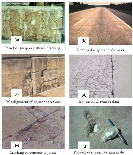
Figure 9. Typical symptoms of ASR.
Field performance survey of concrete structures can be used to determine the potential alkali-reactivity of concrete aggregates (CSA A23.1). When field performance is used for that purpose (CSA A23.1):
Evaluating potential alkali-reactivity from field performance requires the involvement of an engineer and/or scientist with experience of assessing ASR in concrete structures.
A wide variety of standard test methods is available for identifying potentially reactive aggregates. Table 6 lists the tests that have been standardized by ASTM. Only the concrete prism test (ASTM C1293) and the accelerated mortar bar test (ASTM C1260) are currently recommended for use in identifying reactive aggregates. Petrographic examination of aggregates (ASTM C295) is often seen as the essential first step of an ASR testing program; however, it should not be used to accept an aggregate source without expansion testing in concrete or mortar. (ASTM C1105 is recommended for evaluating alkali-carbonate reactive rocks). ASTM C 1567 is used to test the efficacy of pozzolans and slags for controlling concrete expansion due to ASR rather than to identify reactive aggregates.
Table 6. ASTM test methods related to alkali-aggregate reaction.
C1293-05 Standard Test Method for Concrete Aggregates by Determination of Length Change of Concrete Due to Alkali-Silica Reaction1,3 C1260-05a Standard Test Method for Potential Alkali Reactivity of Aggregates (Mortar Bar Method)1 C227-03 Standard Test Method for Potential Alkali Reactivity of Cement Aggregate Combinations (Mortar Bar Method) C289-03 Standard Test Method for Potential Alkali-Silica Reactivity of Aggregates (Chemical Method) C1105-05 Standard Test Method for Length Change of Concrete Due to Alkali-Carbonate Rock Reaction C295-03 Standard Guide for Petrographic Examination of Aggregates for Concrete2 C1567-04 Standard Test Method for Determining the Potential Alkali-Silica Reactivity of Combinations of Cementitious Materials and Aggregate (Accelerated Mortar-Bar Method)3 C441-05 Standard Test Method for Effectiveness of Mineral Admixtures or Ground Blast Furnace Slag in Preventing Excessive Expansion of Concrete Due to the Alkali-Silica Reaction 1Only the concrete prism test (ASTM C1293) and the accelerated mortar bar test (ASTM C1260) are currently recommended for use in identifying reactive aggregates. 2Often seen as the essential first step of an ASR testing program; however, it should not be used to accept an aggregate source without expansion testing in concrete or mortar. 3Only the modified version of the concrete prism test (ASTM C 1293) and the ASTM C 1567 are recommended for evaluating the efficacy of pozzolans and slag for controlling expansion due to ASR. |
The concrete prism test is generally considered to be the most reliable laboratory test in its ability to predict field performance. In this test, concrete prisms are stored in sealed containers over water at 38 °C (100 °F). Figure 10 shows the test setup, and figure 11 provides the length change measurements. The test uses the following parameters:
The appendices to ASTM C1293 (the standard test method) and ASTM C33 (the specification for aggregates) consider aggregates that produce expansions greater than or equal to 0.04 percent at 1 year to be potentially deleteriously reactive. In Canada, in a test almost identical to ASTM C1293
(CSA A23.2-27A), the expansion after 12 months is used to classify the aggregate as (i) nonreactive (expansion < 0.04 percent), (ii) moderately reactive (expansion between 0.04 and 0.12 percent) or
(iii) highly reactive (expansion > 0.12 percent). This test method can also be used to evaluate preventive measures (see section 3. 5).
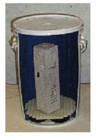
Figure 10. Concrete prism test—prisms stored over
water in sealed containers.
Figure 11. Concrete prism test-length change measurements (ASTM C1293)[1].
The accelerated mortar bar test yields results in as little as 16 days. In this test, mortar bars containing the aggregate under test are immersed in an alkaline solution at elevated temperature (1 N NaOH at 80 °C (176 °F)) and the length change of the bars is monitored. The test uses the following parameters:
ASTM suggests the following interpretation of expansion results:
However, other parties have suggested extending the immersion period to 28 days and using the same or a lower expansion limit (i.e., 0.08 percent). Details of the test are shown in figure 12. The accelerated mortar bar test can also be used to evaluate preventive measures in accordance with ASTM C1567 (see section 3.5). ASTM C1567 follows identical procedures in terms of storage conditions and measurements as ASTM C1260; the only difference is the incorporation of SCMs in the mortar mixture.
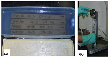 |
| Figure 12. Accelerated mortar bar test (ASTM C1260): (a) view from the top of four rectangular concrete samples, under water in a blue rectangular container; (b) measuring a concrete sample for length change using a digital comparator. |
The risk of damage due to ASR in new concrete can be minimized by following one or more of the following strategies:
The use of nonreactive aggregate is the most obvious measure for preventing damaging alkali-silica reaction. Aggregates that do not cause deleterious expansion when tested in accordance with ASTM C1293 and ASTM C1260 are unlikely to cause damage due to ASR when used in the field. However, because there is a small risk of ASR even when aggregate sources have been shown to be "nonreactive" by testing, some agencies still specify that additional precautions be taken (e.g., use of SCM or limiting the alkali content of the concrete). Furthermore, in some locations "nonreactive" aggregates may be scarce and potentially reactive aggregates can be used safely when appropriate preventive measures are taken.
The risk of damage due to ASR when potentially reactive aggregate is used increases as the alkali content of the concrete increases. Figure 13 shows the relationship between expansion of concrete prisms and the alkali content of concrete containing a reactive siliceous limestone. It can be seen that, in laboratory specimens, deleterious expansion only occurs with this aggregate when the alkali content exceeds 3.0 kg/m3 (5 lb/yd3) Na2Oe. The alkali content of portland cement concrete is calculated by multiplying the cement content by the alkali content of the cement, as shown in table 7.
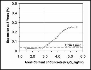
Figure 13. Effect of the alkali content of concrete on the expansion of prisms.
Table 7. Calculation for alkali content of portland cement concrete.
| Alkali content of concrete (kg/m3Na2Oe) = Cement content of concrete (kg/m3) x alkali content of cement (percent Na2Oe)/100 | (3) |
| For example, the alkali content of a concrete mixture containing 350 kg/m3 of Portland cement which has an alkali content of 0.91 percent Na2Oe is: | |
| 350 kg/m3 x 0.91 % NA2Oe / 100 = 3.19 kg/m3 Na2Oe | (4) |
| 588 lb /yd3 x 0.91 % NA2Oe / 100 = 5.35 lb/yd3 Na2Oe | (5) |
It should be noted that expansion may occur in the field at lower alkali contents than that found necessary to cause expansion in the laboratory. The reason for this is that a portion of the alkalies may be lost through leaching under the conditions of the concrete prism test (Thomas et al., 2005). For example, the aggregate for which expansion data are presented in section 3.4.2 caused expansion and cracking of field-exposed concrete blocks (approximately 0.6 by 0.6 by 2.0 m (2 by 2 by 6 ft.)) with an alkali content of just 1.9 kg/m3 (3.2 lb/yd3) Na2Oe (Rogers et al., 2004).
Limits on alkali contents in national specifications vary between different countries with values in the range of 2.5 to 4.5 kg of Na2Oe per cubic meter (4.2 to 7.6 lb of Na2Oe per cubic yard) being used (Nixon and Sims 1992). In Canada (CSA A23.1-27A), a range of alkali limits are specified depending on the level of prevention required; these are presented in table 8.
Table 8. Range of alkali limits (CSA A23.1-27A).
| Level of Prevention Required | Alkali Limit (Na2Oe) | |
|---|---|---|
| kg/m3 | lb/yd3 | |
Mild |
3.0 |
5.0 |
Moderate |
2.4 |
4.0 |
Strong |
1.8 |
3.0 |
Exceptional |
1.8 + SCM |
3.0 + SCM |
In Standard Practice CSA A23.2-27A, the level of prevention required is determined by considering the reactivity of the aggregate proposed for use, the exposure condition, the size of the element and the design life of the structure to be built. As indicated in table 8, the required levels of prevention vary from "mild" to "exceptional" as a function of the above factors, with corresponding alkali limits for prevention purposes. For example, "mild" preventions (e.g., maximum total concrete alkali content of 3 kg/m3 (5 lb/yd3)) are required for massive concrete elements incorporating a moderately reactive aggregate (i.e., inducing a concrete prism expansion greater than 0.04 percent but less than 0.12 percent) in a dry environment (e.g., interior elements of buildings). The level of prevention would increase to "moderate" (maximum total concrete alkali content of 2.4 kg/m3 (4 lb/yd3)) if such a moderately reactive aggregate were used in an exposed structure with a design life of less than 75 years (e.g., sidewalk or pavement), or "sstrong" (maximum total concrete alkali content of 1.8 kg/m3 (3 lb/yd3)) if used in an exposed structure with a design life of greater than 75 years (e.g., a bridge or a dam). An "exceptional" level of prevention would be required when a highly reactive rock is used in the same type of structure. For the latter, it is recommended not only to limit the total concrete alkali content at less 1.8 kg/m3 (3 lb/yd3), but also to use a sufficient amount of SCM.
Specifying the use of low-alkali cement (< 0.60 percent Na2Oe) or limiting the total alkali content in concrete under a certain level, as a means for preventing ASR when reactive aggregates are used, may however not be sufficient / effective in all cases. There have been a number of cases of ASR in concrete structures built with low-alkali cement. For example, a concrete with 400 kg/m3 (~670 lb/yd3) of cement with an alkali content of 0.55 percent Na2Oe will have a total alkali content of 2.2 kg/m3 (3.7 lb/yd3) Na2Oe, which is sufficient to produce ASR damage with some aggregates. Also, limiting the alkali content in concrete may not provide sufficient protection if the concrete is exposed to external sources of alkalies (e.g., deicing chemicals, seawater, etc.)
One of the most efficient means of controlling ASR in concrete containing reactive aggregates is the appropriate use of supplementary cementing materials (SCM). Such materials include pozzolans (e.g., fly ash, silica fume, calcined clay, or shale) and ground-granulated blast furnace slag. Almost any SCM can be used for this purpose provided it is used in sufficient quantity (figure 14). The amount of SCM required generally increases as:
Pozzolans, such as silica fume, which have a high content of reactive silica and low levels of calcium and alkali tend to be very efficient in controlling ASR and can be used at relatively low levels of replacement (typically 7 to 15 percent[2]) for this purpose. On the other hand, SCM with relatively high levels of calcium and lower amounts of silica, such as Class C fly ash or slag, generally need to be used at replacement levels of 35 percent or more. Low-calcium Class F fly ash is relatively more efficient (i.e., can be used at lower replacement levels) than Class C fly ash or slag, but has to be used at higher replacement levels than silica fume. Figure 14 shows typical expansion behavior of concrete containing high-alkali cement (see note below), reactive aggregate, and different types of SCM.
Figure 14. Effect of SCM on the expansion of concrete (using concrete prism test).
Ternary cement blends, which contain three different cementing materials (portland cement plus two SCMs) have been found to be very effective in controlling ASR, especially blends containing silica fume plus either Class F fly ash or slag. Relatively low levels of silica fume (3 to 5 percent) together with moderate levels of Class F fly ash (15 to 20 percent) or slag (25 to 35 percent) have been shown to be effective (Shehata and Thomas, 2002; Bleszynski et al., 2002).
The concrete prism test (ASTM C1293) can be modified to determine the amount of SCM required to control expansion with a particular reactive aggregate. The method is described in CSA A23.2-28A-04. When testing SCM, the portland cement component of the mixture is partially replaced with the SCM. Various replacement levels can be used to determine the minimum level required to suppress expansion. The alkali content of the portland cement component of the mixture should be maintained at 1.25 percent Na2Oe (by adding NaOH, usually in liquid form, to the mixing water) to a cement with 0.90 ± 0.10 percent Na2Oe). When evaluating preventive measures, the test period should be extended to 2 years and the measure shall be considered effective if the expansion at this age is not greater than 0.04 percent.
The accelerated mortar bar test (ASTM C1567) can also be used to determine the amount of SCM required to control expansion with a particular aggregate. The portland cement component of the mix is partially replaced with the SCM under test; different replacement levels can be used to determine the minimum level of SCM required to control expansion. The preventive measure is considered effective if the expansion after 2 weeks immersion in the alkaline solution is not greater than 0.10 percent (Thomas et al., 2005). This test is generally not considered to be as reliable as the concrete prism test for evaluating SCM, and it is recommended that the results of the accelerated test be confirmed by the longer-term concrete test.
Methods for mitigating the effects of ASR can be divided into two categories: (1) mitigating the symptoms of distress and (2) addressing the cause of distress.
Methods for mitigating the symptoms include filling cracks; cutting joints to allow further expansion to take place, thereby relieving internal stresses within the concrete or pressures on adjacent members or structures; and providing restraint to further expansion.
Caulking cracks with an epoxy grout (or similar compound) can help protect embedded reinforcement and reinstate the integrity of the cracked concrete. However, it will not significantly retard the rate of reaction and expansion, and new cracks will inevitably form with time if the reaction is allowed to proceed.
Cutting joints to allow for expansion to take place has been used in a number of hydraulic structures, with the principal aim in these cases being to relieve stresses on embedded mechanical equipment such as sluice gates or turbines. Joints can also be cut to isolate expanding structures from adjacent structures or to relieve internal stresses in pavements. Providing space for expansion does not deal with the reaction, and it is likely that the expansion and cracking will continue.
Providing restraint in the form or rock anchors or post-tensioned tendons also has been used in hydraulic structures to prevent unwanted expansion and distortion of the structure. Fiber-reinforced polymers (FRPs) have been used to wrap elements such as columns.
The only two practical means for addressing the cause of damage (i.e., to retard or prevent further reaction), are to either dry the concrete to eliminate the moisture required to sustain ASR or to change the nature of the reaction by introducing lithium compounds.
Silane sealers have been used successfully to reduce the relative humidity in ASR-affected concrete piers (Kojima et al., 1992), railway sleepers (Oberholster et al., 1992) and median barriers (Bérubé et al., 1998). Silanes applied to concrete render the surface of the concrete hydrophobic and prevent the ingress of liquid water into the concrete. However, water vapor can still exit through the layer, reducing the moisture content, and hence reducing the relative humidity, with time. Figure 15 shows a photograph of silane-treated and untreated sections of a barrier wall in Quebec.
The use of lithium compounds to treat ASR-affected concrete structures is discussed in chapter 5.
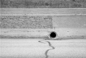
Figure 15. Barrier wall in Quebec-the section of the wall to
the right of the picture has been treated with a silane sealer.