U.S. Department of Transportation
Federal Highway Administration
1200 New Jersey Avenue, SE
Washington, DC 20590
202-366-4000
Federal Highway Administration Research and Technology
Coordinating, Developing, and Delivering Highway Transportation Innovations
 |
| This report is an archived publication and may contain dated technical, contact, and link information |
|
Publication Number: FHWA-RD-03-088 Date: November 2003 |
Previous | Table of Contents | Next
The Dynamic Load Response (DLR) module contains instrumentation response data collected at SPS test sections in North Carolina and Ohio.
Four PCC pavement sections on the SPS-2 project in North Carolina were instrumented to measure pavement response under controlled loading conditions. Both deflections and strains at defined positions within the slab were recorded under loading by known vehicles at six locations (corner, midslab edge, and midslab outer wheel path) within two adjacent slabs. Pavement surface strains were obtained by surface-mounted strain gauges located at midslab within the wheel path and midslab along the slab edge. A total of 30 traces were obtained from each pass of the loaded vehicle with multiple repetitions at multiple speeds collected at various times of the day. The LTPP technical support services contractor and the North Carolina Department of Transportation (DOT) worked jointly during data collection operations. The LTPP technical support services contractor has summarized the raw data files to determine the characteristic peaks and valleys along the individual response traces.
Ohio DOT and a consortium of Ohio universities took DLR measurements on instrumented sections in Ohio. Measurements were taken on both SPS-1 and -2 AC and PCC test sections. The data were collected using similar techniques to the LTPP DLR data collected in North Carolina.
Because of the complex nature of this data module, users interested in analyses of these data should consult the technical references listed in appendix A.
Common fields unique to the DLR tables that can be used to link related data in associated tables to each other include TEST_NAME, RUN_NUMBER, and TAG_ID.
TEST_NAME represents data collection events on each test site. A data collection event can occur on a single day or over several consecutive test days. DLR_TEST_MATRIX provides a link between TEST_NAME in the DLR_MASTER_* tables and TEST_DATE. RUN_NUMBER in the DLR_TEST_MATRIX table can be used to differentiate between multiple test dates occurring during a single data collection event as indicated by TEST_NAME. This link to TEST_DATE is needed for DLR measurements on PCC sections; TEST_DATE is included in the tables containing measurements on AC test sections. The last letter in TEST_NAME indicates the temporal order of testing: "a" represents the first data collection event, "b" indicates the second, and so on.
RUN_NUMBER represents the sequential order of runs by test trucks during the data collection event as defined by TEST_NAME. RUN_NUMBER is used to relate the characteristics of the test truck and test speed stored in the DLR_TEST_MATRIX and DLR_TRUCK_GEOMETRY tables to the measured pavement responses stored in the other DLR data tables. For each TEST_NAME event, the run number starts with 1 and is increased by 1 for each successive pass by the test trucks.
TAG_ID is the name assigned to the sensors installed on each test section. The combination of STATE_CODE, SHRP_ID, and TAG_ID uniquely identifies each response sensor. The TAG_ID name also identifies the type of sensor, although the DLR data tables are based on the type of measurement. TAG_ID is a mapping on the CHANNEL the sensor is wired to on the data acquisition device.
The relational structure of the tables in the DLR module is illustrated in figure 3:
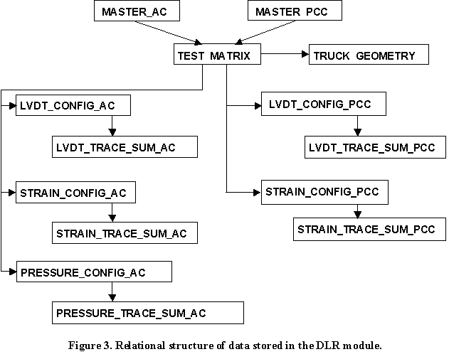
The name and contents of tables in the DLR module are as follows:
DLR_MASTER_AC: This table contains site and instrumentation summary information for sections with AC surfaces. One record exists in this table for each DLR measurement cycle as defined by the TEST_NAME field.
DLR_MASTER_PCC: This table contains site and instrumentation summary information for sections with PCC surfaces. One record exists in this table for each DLR measurement cycle as defined by the TEST_NAME field.
DLR_TEST_MATRIX: This table contains information on each test sequence, including test date, test time, test vehicle, vehicle speed, and vehicle offset. TRUCK_ID and STATE_CODE are used to link to information on truck geometry stored in the DLR_TRUCK_GEOMETRY table.
DLR_LVDT_CONFIG_AC: This table contains Linear Variable Differential Transformer (LVDT) gauge settings and location information for instrumented AC test sections.
DLR_LVDT_TRACE_SUM_AC: This table contains response trace summaries from LVDT measurements on AC test sections. The response trace is reduced to a series of up to 10 points to capture the significant events in the response trace (most traces contain 3 to 5 points).
DLR_LVDT_CONFIG_PCC: This table contains LVDT gauge settings and location information for instrumented PCC test sections.
DLR_LVDT_TRACE_SUM_PCC: This table contains response trace summaries from LVDT measurements on PCC test sections. The response trace is reduced to a series of up to 10 points to capture the significant events in the response trace.
DLR_PRESSURE_CONFIG_AC: This table contains pressure gauge settings and location information for measurements on AC test sections.
DLR_PRESSURE_TRACE_SUM_AC: This table contains response trace summaries from pressure measurements on AC test sections. The time-response trace is reduced to a series of up to 10 points to capture the significant events in the response trace (most traces contain 3 to 5 points).
DLR_STRAIN_CONFIG_AC: This table contains strain gauge information, configuration settings, and location information for measurements on AC test sections.
DLR_STRAIN_TRACE_SUM_AC: This table contains response trace summaries from strain measurements on AC test sections. The time-response trace is reduced to a series of up to 10 points to capture the significant events in the response trace (most traces contain 3 to 5 points).
DLR_STRAIN_CONFIG_PCC: This table contains strain gauge information, configuration settings, and location information for measurements on PCC test sections.
DLR_STRAIN_TRACE_SUM_PCC: This table contains response trace summaries from strain measurements on PCC test sections. The time-response trace is reduced to a series of up to 10 points to capture the significant events in the response trace.
DLR_TRUCK_GEOMETRY: This table contains information on the axle spacing, tire type and pressure, and axle width of the test trucks used for the DLR tests.

