U.S. Department of Transportation
Federal Highway Administration
1200 New Jersey Avenue, SE
Washington, DC 20590
202-366-4000
Federal Highway Administration Research and Technology
Coordinating, Developing, and Delivering Highway Transportation Innovations
 |
| This report is an archived publication and may contain dated technical, contact, and link information |
|
Publication Number: FHWA-RD-01-163 Date: March 2002 |
Previous | Table of Contents | Next
Partial-Depth Repairs
Partial-depth repairs are one rehabilitation method that can be used to repair localized deteriorated areas caused by MRD. These repairs consist of the removal of concrete near the surface and replacement with an acceptable patch material, usually a rapid-setting material to limit closure time. However, their effectiveness is limited to smaller areas where the deterioration is confined to the upper one-third of the concrete slab. Partial-depth repairs are most commonly performed along transverse and longitudinal joints.
Examples of MRD that are candidates for partial-depth repairs are freeze-thaw deterioration of cement and deicer scaling/deterioration. These deterioration mechanisms typically result in scaling, crazing, or map cracking at the pavement surface. For partial-depth repairs to be cost effective, the deterioration must not be too widespread. Deteriorated areas requiring multiple partial-depth repairs can be repaired more cost effectively through other rehabilitation methods, such as full-depth repairs or overlays.
Furthermore, the deterioration must be limited to the upper one-third of the slab. Cores taken at representative areas of deterioration can help determine the extent of deterioration for advance planning. Before placing the patch material, the patch area should be "sounded" with a hammer to ensure that all deterioration has been removed. When damage is found during construction to be more extensive than anticipated, the repair area should be expanded or converted to a full-depth patch, if necessary. The repair will not perform adequately if the deterioration is not completely removed.
Partial-depth repairs are not recommended for MRDs that extend beyond the upper third of the slab. Some MRDs initiate and deteriorate more rapidly at the bottom of the slab where moisture and deleterious chemicals are more readily available. Freeze-thaw deterioration of aggregate and external sulfate attack are examples of such distress types. Other MRD, such as ASR and internal sulfate attack, occur throughout the entire slab. For these distress types, partial-depth repairs are not a practical treatment because they do not address the entire extent of the deterioration and the patch itself will likely become debonded and quickly deteriorate.
A wide variety of materials are available for use in partial-depth patches. These include many rapid setting and high-early strength materials designed to reduce closure times. The selection of the most appropriate material depends on available curing time, ambient temperature, cost, and size of the repairs. Examples of materials include rapid setting cements, Duracal, Set 45, Five Star HP, and Percol FL. Bituminous patches are not recommended for repair of MRD on concrete pavements.
Full-Depth Repairs
Full-depth repairs are generally a better alternative than partial-depth repairs for addressing pavement deterioration caused by MRD. These repairs consist of the removal of isolated deteriorated areas through the entire depth of the slab and replacement with a high-quality material. Full-depth repairs are a widely used means of repairing localized deterioration at joints or cracks. As previously noted, MRDs are generally more severe along joints and cracks due to increased exposure to deleterious substances, which makes full-depth repairs an appropriate repair method.
In addition to replacing the deteriorated concrete, full-depth repairs also restore the load transfer at the joints. Consequently, full-depth repairs are an ideal method of repair for joints that have locked up and spalled due to corrosion of dowel bars. Likewise, wide cracks and punchouts where the reinforcing steel has corroded are also ideal candidates for full-depth repairs.
As with all repair methods, full-depth repairs should be viewed not as a solution to a durability problem but rather as a means to extend the life of the pavement. Because the problem is materials related, it cannot be completely remedied by replacing a portion of the pavement. However, full-depth repairs of badly deteriorated areas can improve the serviceability and buy additional life for the pavement. For pavements exhibiting ASR, full-depth repairs are only recommended to repair isolated areas that compromise the ride quality or safety of the users.
Because deterioration caused by MRD is often confined to transverse joints, full-depth repairs are an effective method of rehabilitation. The major shortcoming is that full-depth repairs create two joints where there originally was only one joint. In effect this adds one other potential problem area. Freeze-thaw deterioration of aggregate, for example, has been found to appear along the newly formed joints within 5 years. Treating the joint and possibly the adjacent concrete with a surface sealer can help prevent the recurrence, but even with preventive measures, full-depth repairs should be viewed only as a means to extend the life of the pavement.
The use of dowel bars is strongly recommended for full-depth repairs. Dowel bars provide better long-term performance by reducing vertical movements, rocking, and faulting. On high-volume roadways, the use of dowel bars is recommended on both sides of the patch. On lower volume facilities, tiebars may be used on the approach side of the patch with dowels used on the leave side of the patch. On CRCP, continuity of the reinforcing steel should be reestablished through the full-depth repair.
Slab Replacement
For deteriorated areas that are not isolated along joints or cracks or for large areas of deterioration, slab replacement may be a better alternative than full-depth repairs. Removal and replacement of multiple full-depth repairs becomes expensive, so it can become more cost effective to replace the entire slab. The problem is that MRDs generally occur throughout the entire project and are not likely to be limited to several slabs. Thus, it should be recognized that slab replacement does not completely address the durability problem (unless all slabs are replaced). Slab replacement can also be used in conjunction with other rehabilitation techniques to restore the pavement condition to an acceptable level.
Diamond Grinding
Diamond grinding uses closely spaced diamond saw blades to remove a thin layer of concrete from the pavement surface. This process corrects surface irregularities, provides a smooth riding surface, and improves the frictional characteristics of the pavement. For durability problems, the purpose of diamond grinding is simply to “buy some time” until more permanent rehabilitation can be conducted. As with the other rehabilitation methods, diamond grinding does not directly address the durability problem. Although diamond grinding will remove deteriorated areas from the pavement surface, a new layer of concrete will be exposed and will also deteriorate with time.
For diamond grinding to be feasible, the deterioration must be limited to the pavement surface. Diamond grinding should not be used in an attempt to repair more extensive deterioration. Surficial scaling and map cracking are examples of distress types that are good candidates for diamond grinding. Scaling can be attributed to the use of deicing chemicals or freeze-thaw deterioration of the cement paste. Map cracking is often associated with MRD that involves chemical reactions, such as ASR, ACR, and sulfate attack. Diamond grinding is also an effective method of restoring ride quality in conjunction with other repair methods such as partial-depth and full-depth repairs. If conducted, diamond grinding should be performed after any rehabilitation techniques (e.g., partial-depth or full-depth repairs) but before any surface treatment methods.
Overlay
Both AC and PCC overlays are common concrete pavement rehabilitation alternatives. Pavements with MRD are not good candidates for bonded PCC overlays whereas unbonded PCC overlays are a more feasible option. One problem with overlays is that they do not address a pavement’s durability problem. Distress in the underlying pavement will continue to deteriorate and will definitely affect the performance of the overlay. Additionally, the presence of the overlay may accelerate the rate of development as it traps more moisture in the existing pavement. As a result, the effect of MRD on the overlay must be taken into account during design. Means to account for existing MRD include preoverlay repairs of badly deteriorated areas and the use of a thicker overlay than would normally be used. Otherwise, it should be expected that the overlay will not provide the same performance or service life as an overlay placed over a pavement without MRD.
Given that an overlay covers the pavement surface and prevents direct exposure to the underlying pavement (reducing the depth of freezing temperatures), an overlay could also be considered a treatment method. The thought is that by covering the concrete with an AC overlay, the concrete will not experience the same number of freeze-thaw cycles. However, its effectiveness in this regard is limited. Temperature simulations in moderate climates found that a 150-mm overlay was not sufficient to prevent freezing in the underlying concrete pavement (Dempsey 1969). Table 1-6 presents the results of the study for various AC overlay thicknesses.
Although it is true that an AC overlay will reduce the number of freeze-thaw cycles, it can never completely eliminate freeze-thaw cycling in harsh climates. Previous studies have shown that, in order to stop the progression of freeze-thaw deterioration, freezing must be completely prevented; merely decreasing the number of freeze-thaw cycles with an overlay can actually accelerate the rate of deterioration (Janssen 1985; Janssen et al. 1986). Moreover, covering the concrete surface with an AC overlay can trap additional moisture in the pavement, which again can accelerate deterioration. Consequently, AC overlays are not recommended as a long-term solution on pavements with freeze-thaw deterioration of aggregate, but can be used as a temporary solution to buy some time until a more effective long-term solution is implemented.
Distress in the underlying pavement can also reflect through an AC overlay. Preventive measures (e.g., preoverlay repairs and reinforcing fabrics) can reduce or delay the occurrence of reflective cracking but are seldom totally effective at eliminating reflective cracking. An alternative is to fracture the existing pavement before placing an AC overlay, in which case the existing pavement acts a base layer. This option has been successfully used to prevent reflective cracking [National Asphalt Paving Association (NAPA) 1991; FHWA 1998]. However, fracturing the existing pavement will reduce its structural capacity and thus it will require a thicker overlay.
An unbonded PCC overlay is another option (bonded overlays are not recommended on pavements showing MRD). Again, the overlay will not help prevent freeze-thaw cycling in the underlying pavement. However, an unbonded PCC overlay can be more effective than an AC overlay because its performance depends less on the condition of the underlying pavement. Providing uniform support is the most important consideration. The major shortcoming of unbonded PCC overlays is that they need to be thicker than other overlay types. This drawback translates to higher initial construction costs and potential problems with overhead clearances and grade differentials.
Table 1-6. Effect of overlay thickness on freeze-thaw cycling (Dempsey 1969).
|
Location |
AC Overlay |
Number of Freeze-Thaw Cycles |
||
|
0 mm |
50 mm |
100 mm |
||
|
Tulsa, OK |
0 |
31.1 |
9.7 |
3.5 |
|
50 |
11.2 |
2.5 |
1.2 | |
|
100
|
4.7 |
1.0 |
0.4 | |
|
150
|
1.7 |
0.5 |
0.3 | |
|
Topeka, KS |
0 |
52.6 |
17.5 |
7.1 |
|
50 |
28.8 |
7.0 |
5.0 | |
|
100 |
11.5 |
5.5 |
4.0 | |
|
150 |
6.0 |
4.6 |
2.6 | |
|
Lexington, KY |
0 |
42.6 |
15.9 |
6.5 |
|
50 |
23.6 |
6.5 |
3.7 | |
|
100 |
11.5 |
4.1 |
2.6 | |
|
150 |
4.8 |
3.1 |
2.5 | |
|
Evansville, IN |
0 |
40.7 |
¾ |
¾ |
|
50 |
24.2 |
5.2 |
3.9 | |
|
100 |
10.9 |
2.8 |
2.0 | |
|
150 |
2.9 |
2.2 |
1.3 | |
|
Dodge City, KS |
0 |
54.2 |
16.9 |
5.9 |
|
50 |
25.7 |
5.2 |
3.4 | |
|
100 |
10.7 |
3.7 |
2.9 | |
Overlays should be used cautiously over pavements experiencing corrosion of embedded steel. If not repaired prior to overlaying, locked-up joints can lead to blowups in the concrete that will be just as damaging to the overlay. Temporary repairs to maintain serviceability until the pavement can be reconstructed may be a better alternative in this case.
Pavement Reconstruction
The most extreme rehabilitation alternative is total reconstruction of the pavement. This solution corrects an MRD problem and will prevent its recurrence if proper procedures are used to prevent MRD in the new pavement. Because durability problems are not often limited to isolated areas within the pavement, reconstruction is often the only practical long-term alternative. Of course, this alternative is most cost effective on badly deteriorated concrete pavements, where mitigation methods are ineffective and repairs are too numerous and costly. Reconstruction may be the only option on pavements with MRDs that have progressed to high severity levels.
Pavement Recycling
Another form of reconstruction is pavement recycling. This process involves removal and crushing of the existing concrete for use as aggregate in the reconstructed pavement. Recycling offers several benefits over reconstruction, including reduced cost and conservation of materials. Recycling has been a viable option for decades but has only recently gained acceptance for pavements exhibiting durability problems. In such instances, adjustments to the mix design procedures must be made to prevent or limit the recurrence of durability problems in the recycled pavement. With these adjustments, recycling of concrete pavements exhibiting MRD can provide performance equivalent to that of conventional mixes (Wade et al. 1997).
The identification and analysis of MRD are critical steps in the selection of the most appropriate treatment or rehabilitation option. Not only is it important to identify the existing distress, but it is also important to understand the cause of the distress to prevent its recurrence. Once correctly identified, there are still multiple options from which to choose. Table 1-7 summarizes the potential treatment and rehabilitation alternatives for each MRD. These methods should only be viewed as possible alternatives for the particular MRD. Some methods will be more effective than others, as discussed previously. In addition, multiple MRD can appear concurrently, as well as with other distress types. The treatment and repair options must address all distress types.
Evaluation and selection of the proper repair material and technique are critical to ensuring adequate performance of the treatment or rehabilitation method over its expected performance life. The evaluation and selection process involves a large number of technical, economical, and practical factors. For example, the repair method must address the cause and prevention of MRD, as well as provide a certain level of serviceability over its performance life. Also, the proposed solution must be economically feasible in that it should provide a cost-effective solution in comparison to other potential alternatives. Finally, the proposed solution must be constructible using available materials, techniques, and equipment.
Selecting an appropriate treatment is a complex process. The selection of the most appropriate alternative must address the following questions:
Table 1-7. Available treatment and rehabilitation options.
|
Type of |
Possible |
Possible |
|---|---|---|
|
Freeze-Thaw Deterioration of Cement Paste |
Surface sealing |
Partial-depth repairs |
|
Deicer Scaling/Deterioration |
Surface sealing |
Partial-depth repairs |
|
Freeze-Thaw Deterioration of Aggregate |
Surface sealing |
Full-depth repairs |
|
Alkali–Silica Reactivity |
Lithium salts |
Full-depth repairs |
|
Alkali–Carbonate Reactivity |
Crack filling |
Full-depth repairs |
|
External Sulfate Attack |
NaCl treatment |
Full-depth repairs |
|
Internal Sulfate Attack |
NaCl treatment |
Full-depth repairs |
|
Corrosion of Embedded Steel |
Surface sealing |
Full-depth repairs |
This section discusses some of the key issues that must be balanced when comparing alternatives and selecting the optimal solution.
Distress Severity
The most appropriate treatment or rehabilitation method for pavements exhibiting MRD depends to a large extent on the severity of deterioration. As a general rule, treatment methods are most applicable to pavements exhibiting low-severity MRD. Pavements exhibiting high-severity MRD, on the other hand, are usually better candidates for rehabilitation methods. However, the selection will depend on a number of other criteria, including the type of distress, the extent of the deterioration, overall pavement condition, traffic volumes, and anticipated life of the pavement.
Treatment methods are designed to stop or at least slow the rate of deterioration and are thus most effective for addressing MRD in its early stages of development. Treatment methods address the cause of deterioration. By applying treatment methods in the early stages of deterioration, the distress may be prevented (or at least delayed) from progressing to the point where it causes a serviceability problem.
Some treatment methods directly treat the cause of the distress by eliminating or altering an adverse reaction that creates the distress. Examples include the use of lithium salts to address ASR and the use of NaCl to address sulfate attack. Other methods, such as application with an HMWM, are designed to strengthen the pavement and prevent deterioration to the point where extensive repair is required. Still other methods are designed to hinder the exposure of the pavement to deleterious substances.
All of these methods must be applied in the early stages of deterioration. Once the deterioration has progressed to the point where it affects the serviceability or safety of the users, treatment methods will no longer be effective. For one, they will not address the serviceability or safety problem. Secondly, treating a pavement with severe distress is not cost effective because it will not eliminate the need for repairs.
Treatments that are designed to limit the exposure to moisture should be used with caution. Most methods are at best only partially effective at performing their intended function. For instance, resealing joints and cracks will not completely eliminate the infiltration of moisture (Hagen and Cochran 1995). Additionally, MRDs that require moisture typically initiate and deteriorate more rapidly at the bottom of the slab. By the time the distress is visible on the surface, the deterioration at the bottom is often too severe for treatment methods to be effective.
As MRDs progress to moderate-severity levels, treatment methods become less effective. This is especially true for distresses that initiate at the bottom of the slab, such as freeze-thaw deterioration of aggregate and external sulfate attack. The one exception is the use of crack fillers such as HMWM. To be effective, crack fillers must be able to penetrate the pavement surface. Cracks that are slightly open provide easier access for the filler material to penetrate.
Often, a combination of treatment and rehabilitation methods will be the best alternative for moderate-severity MRD. Rehabilitation methods should be employed to address deteriorated areas and restore serviceability. Treatment methods can then be used to prevent further progression of the MRD. For example, salt scaling can first be addressed through diamond grinding, followed by a surface sealer to prevent continued deterioration.
Rehabilitation methods are generally the only available alternative for MRDs that have progressed to high-severity levels. At this point, the pavement is too deteriorated, and treatment methods no longer offer an effective means of addressing the problem. Badly deteriorated areas must be removed and replaced with a suitable material in order to restore serviceability. Full-depth repairs are a common technique used to address MRDs that are limited to transverse joints and cracks. As the deterioration becomes more extensive, major rehabilitation techniques such as overlays or reconstruction may be the only viable alternative.
Distress Quantity
Another important consideration when selecting the most appropriate alternative is the amount of distress, both in terms of the extent and depth of deterioration. The distress mechanism influences the extent and depth of deterioration and must be considered when determining the treatment or rehabilitation method.
Distresses that are concentrated at joints and cracks are good candidates for localized techniques such as partial-depth and full-depth repairs. Alternatively, more widespread distresses require more extensive techniques such as a chemical treatment, diamond grinding, or an overlay. They cannot be addressed cost effectively with localized repair methods.
Examples of MRD that are candidates for localized rehabilitation techniques include freeze-thaw deterioration of aggregate and corrosion of embedded steel. Both distresses are concentrated at joints and cracks where they have greater exposure to moisture and deleterious chemicals. These distresses generally do not occur or are much less severe in other areas of the slab. Consequently, full-depth repairs are the most common method used to address these distresses. Salt scaling can also occur in localized areas such as depressions where water puddles for extended periods and poorly finished areas. Partial-depth repairs can be used to address these localized areas of deterioration if they are restricted to the upper third of the slab.
More extensive MRDs include ASR, ACR, and sulfate attack. These distresses involve a reaction between constituent materials within the concrete. Although they can be more severe near joints and cracks, they generally occur throughout the entire slab. More extensive treatments must therefore be employed to address the deterioration. Chemical treatments and surface sealers are examples of two treatment methods that address widespread deterioration. Widespread rehabilitation methods include diamond grinding, overlays, and reconstruction.
Along with the extent of deterioration, the depth of deterioration is also a determining factor in selecting the appropriate method. The extent of deterioration at the bottom of the slab is just as important as the surface condition when selecting the most appropriate treatment method. Many MRDs initiate at the bottom of the slab and progress upward. By the time the distress is visible at the surface, it can be quite extensive at the bottom of the slab. Some treatment and rehabilitation methods only address deterioration at the slab surface and will not be effective for deterioration that extends through the depth of slab.
Coring at representative locations throughout the pavement is recommended to examine the extent of deterioration through the depth of the slab. At least two cores should be taken along transverse joints, longitudinal joints, cracks, and midslab locations. This preliminary investigation is useful for planning purposes. Nonetheless, if the deterioration is found to be more extensive during the construction phase, adjustments must be made. For instance, a partial-depth repair requires that the deteriorated area be completely removed. If the deterioration extends beyond the upper third of the slab thickness, complete removal and a full-depth repair are called for. Failure to remove the extent of deterioration will result in premature failure of the repair.
Overall Pavement Condition
The selection of the most appropriate treatment or rehabilitation method must consider the overall pavement condition and not just the MRD itself. The extent and severity of other distress types are equally important and must also be addressed. The most cost-effective solution is one that addresses all distress types simultaneously. In some cases, this may require a combination of two or more treatment or rehabilitation methods.
Just because a method is the most effective treatment or rehabilitation option for a particular MRD does not mean it is the most appropriate alternative for the pavement. For instance, the most effective method for a pavement exhibiting freeze-thaw deterioration of aggregate that is confined to the joints might be treatment with a HMWM. However, if the joints are also faulted or locked-up, full-depth repair will likely be a more cost-effective option because it addresses both problems.
Similarly, the selected alternative must fit in with the future plans of the roadway. It would be unwise and wasteful to apply a treatment to address ASR when the pavement is expected to receive major rehabilitation in a few years. Along the same lines, the rate of deterioration should also be considered. For example, the rate of expansion caused by DEF follows an S-shaped curve (Thaulow et al. 1996a). The selection of the treatment or repair option should thus consider the point in the reaction process. Expansion due to DEF typically occurs between 2 and 6 years after construction.
Predicted Performance
The expected performance of an MRD treatment alternative is a key issue in the selection process. Not only is it important to ensure that the method will effectively address the problem, but it is also important to know how long the pavement will provide acceptable serviceability once the method is applied. The performance life of the method, along with the cost of the method, are the major considerations in the conduct of a life cycle cost analysis.
The past performance of treatment and rehabilitation methods for each MRD has been presented. Some of the MRDs are extremely complex, so there still exist some unknowns as to the exact mechanisms and causes of the distress. Likewise, many of the available treatments to address MRD are still in the experimental stages. Consequently, little or no field performance data are available for many of the available methods, especially for some of the treatment alternatives. These factors add to the difficulty of predicting the increased performance life through application of the treatment or rehabilitation method. Agencies may need to experiment with treatments on a small scale to gauge their effectiveness.
The predicted performance (life) of both the existing pavement and the treatment or rehabilitation method must be considered together. It would be foolish to apply a treatment or rehabilitation that will last 10 years when the pavement is expected to fail by other means within 5 years. Frequently the best solution is to apply lower cost methods as a temporary fix to the problem, designed to maintain rideability while more permanent solutions are planned.
Life Cycle Cost Analysis
A life cycle cost analysis procedure provides a valuable tool for selecting the alternative that will provide the required performance at the lowest cost (i.e., the most cost-effective alternative). The procedure needs to consider all costs associated with a given alternative, including initial application costs, future maintenance and rehabilitation costs, user costs, and salvage value. Many of these costs are difficult to predict with any accuracy.
For years, a deterministic approach to predicting life cycle costs has been employed. This method uses discrete inputs to predict a discrete cost. Numerous publications are available regarding this approach (for example, Peterson 1985). More recently, there has been increased interest in a probabilistic approach. This approach considers variations in the inputs to compute a range of results and the probability of occurrence. The FHWA has recently developed a Technical Bulletin that provides guidelines for using this approach in pavement design (FHWA 1997).
A life cycle cost analysis should be conducted on each feasible alternative. However, the life cycle cost analysis should not be used as the ultimate decision-maker. Although it is an extremely valuable tool, life cycle costs represent only one of many factors that need to be considered. Factors such as the reliability of the method and overall project planning are equally important.
Summary of Background on Treatment and Rehabilitation Methods
Pavements inflicted with MRD can be addressed through either treatment or rehabilitation methods. Treatment methods focus on eliminating or reducing rate of deterioration and are generally most appropriate on pavements exhibiting low-severity MRD. Rehabilitation methods, on the other hand, involve removal and repair of the distressed area and are most appropriate for addressing high-severity MRD. Moderate-severity MRD must further consider the extent of deterioration or may involve a combination of treatment and rehabilitation methods.
This background presented the state-of-the-practice of treatment and rehabilitation methods designed to address MRD. Currently, there are no clear-cut guidelines to address a particular MRD. Today’s sophisticated equipment has led to sweeping changes in the investigation and identification of MRD. Researchers continue to developing a greater understanding of the distress mechanisms. Although this is an important step, the technology for treating MRD has not yet advanced to the same level. Several treatment methods have been developed and are currently undergoing laboratory and experimental field evaluations. For the most part, however, the treatments have not yet received widespread use in the field.
This section presents a brief review on the approach taken for the selection of the most appropriate treatment or rehabilitation options to address MRD in concrete pavements. The approach is described in detail in the guideline presented in Volume 2 of this Final Report. The process involves consideration of a large number of technical, economical, and practical factors, as well as coordination with the overall pavement condition and future rehabilitation plans. For example, serviceable concrete repairs can result only if the MRD is correctly identified, the proper materials and methods selected, and good construction practices followed. The proposed solution must also be economically feasible in that it should provide a cost-effective solution in comparison to other potential alternatives. Finally, the proposed solution must be practical, being able to be performed using available materials, techniques, and equipment.
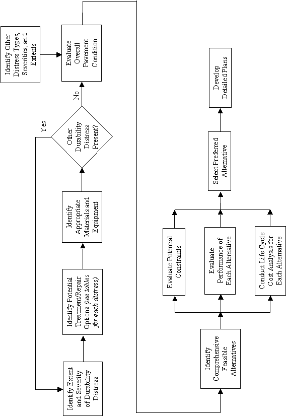
Figure 1-9 presents the recommended flowchart for selecting the preferred treatment or rehabilitation option. Although the overall process is the same regardless of the type of MRD exhibited, portions of the guidelines — such as the selection of feasible alternatives and repair materials — are further broken out by MRD type. The overall process also considers means to address pavements exhibiting multiple distress types, including distresses that are not caused by durability problems.
The first step is to identify the extent and severity of MRD on the existing pavement as described in the first two guidelines in this series. The identification and analysis of MRD is a critical step in the selection of the most appropriate treatment or rehabilitation option. Not only is it important to identify the existing distress, but it is also important to understand the cause of the distress to prevent its recurrence. Assessing the rate of deterioration is also important to determine the progression in the deterioration process.
Once the type, extent, and severity of the MRD are characterized, the next step involves the selection of feasible alternatives, which differ depending on the type(s) of MRD identified. Although the overall process is the same, the feasible alternatives will be different for each MRD. These differences are addressed through corresponding tables that are referenced for each MRD.
The final step is to select the most appropriate option from the list of feasible alternatives. This process involves an evaluation of many considerations, including potential constraints, future rehabilitation activities, expected performance, and life cycle costs.
Recommended Techniques and Materials for Treatment and Rehabilitation
The treatment and rehabilitation techniques discussed in the previous section were adopted in the guideline. The methods to address existing MRD in concrete pavements are divided into treatment methods (those designed to prevent further development of the distress or to reduce its rate of deterioration) and rehabilitation methods (those designed to remove deteriorated areas and to maintain or restore pavement serviceability). As described previously, the available treatment methods include chemical treatments, joint and crack sealing, crack filling, surface sealing, and retrofitted drainage. Drying and restraint are two other treatment methods that were described, but are not practical for pavement applications, and are thus not considered in the treatment options. Rehabilitation methods include partial- and full-depth repairs, slab replacement, diamond grinding, reconstruction, and recycling.
|
|
 |
Feasibility of Available Techniques
A "feasible" alternative must address both the current condition and future performance of the pavement. The identification of feasible alternatives varies significantly depending on the type(s) of MRD occurring. In the guideline, a recommended approach for selecting feasible alternatives is provided in tabular form for each particular MRD type. For each MRD type, the following issues are discussed:
It is noted that it is not uncommon that more than one type of MRD may be at work within a given pavement. Fortunately, many of the treatment and rehabilitation alternatives are equally effective for a number of different MRD types. But it is important to consider the feasibility of the alternatives based on all the mechanisms at work if multiple mechanisms are observed.
Selection of Preferred Alternative
The final series of steps involves the selection of the most appropriate alternative to address the overall needs of the pavement. Selecting the most appropriate method and technique is a complex process involving a large number of technical, economical, and practical considerations. The previous discussions for each distress focus on the effectiveness of the methods. However, many other considerations must be addressed in the final selection process. The selection of the most appropriate alternative must address the following questions:
Some of these issues have already been addressed. This section discusses the remaining issues that must be balanced when comparing alternatives and selecting the optimal solution.
Overall Pavement Condition
The selection of the most appropriate treatment or rehabilitation method must consider the overall pavement condition and not just the MRD itself. The extent and severity of other distress types are equally important and must also be addressed. The most cost-effective solution is one that addresses all distress types simultaneously. In some cases, this may require a combination of two or more treatment or rehabilitation methods.
Possible Constraints
Certain constraints may limit the feasibility of one or more techniques and should be considered in the selection process. At times, these factors take precedence over all other considerations, including the effectiveness of available methods. Such overriding factors may be the result of traffic, climate, materials, or construction considerations. Examples of possible constraints include the following:
Predicted Performance
The expected performance of an alternative is a key issue in the selection process. Not only is it important to ensure that the method will effectively address the problem, but it is also important to know how long the pavement will provide acceptable serviceability once the method is applied. The performance life of the method (along with the cost of the method) are the major considerations in the conduct of a life cycle cost analysis.
The predicted performance (life) of both the existing pavement and the treatment or rehabilitation method must be considered together. For example, it is ineffective to apply a treatment or rehabilitation that will last 10 years when the pavement is expected to fail by other means within 5 years. Often times, the best solution is to apply lower cost methods designed to maintain rideability as a temporary fix to the problem while more permanent techniques are planned.
Life Cycle Cost Analysis
A life cycle cost analysis procedure is a valuable tool for selecting the alternative that will provide the required performance at the lowest cost (i.e., the most cost-effective alternative). The procedure needs to consider all costs associated with a given alternative, including initial application costs, future maintenance and rehabilitation costs, user costs, and salvage value. Many of these costs are difficult to predict with any accuracy.
For years, a deterministic approach to predicting life cycle costs has been employed. This method uses discrete inputs to predict discrete cost. Numerous publications are available regarding this approach (for example, Peterson 1985; Van Wijk 1985). More recently, there has been increased interest in a probabilistic approach. This approach considers variations in the inputs to compute a range of results and the probability of occurrence. The FHWA has published a report that provides guidelines for using this approach in pavement design (Walls and Smith 1998).
A life cycle cost analysis should be conducted on each feasible alternative. However, the life cycle cost analysis should not be used as the ultimate decision-maker. Although it is an extremely valuable tool, it represents only one of many factors that need to be considered. Factors such as the reliability of the method and overall project planning are also important.
Construction and Maintenance Considerations
The methods for addressing MRD often require special considerations for construction and maintenance. The general construction and maintenance recommendations are contained in the guideline for each of the available, practical methods. The recommendations focus on differences or special considerations that are required for pavements with MRD as compared to traditional techniques.
Summary of Recommended Treatment and Rehabilitation Methods
The guideline contained in Volume 2 of this final report presents information on selecting the most appropriate treatment or rehabilitation option to address MRD on concrete pavements. Treatment methods focus on eliminating or reducing rate of deterioration and are most appropriate on pavements exhibiting low-severity MRD. Rehabilitation methods, on the other hand, involve removal and repair of the distressed area and are most appropriate for addressing high-severity MRD. Specific guidelines for each distress type are provided.
A variety of treatment methods are available to address MRD. However, many of the methods are still being tested in the laboratory and have not yet received widespread use in the field. Nonetheless, this guideline presents the most recent information on the effectiveness of the methods to address MRD.
The previous sections in this report have reviewed literature focused on the identification of MRD in concrete pavements and the treatment and rehabilitation alternatives that are available to address the observed deficiencies. This section of the report presents methods to prevent the occurrence of MRD in new pavements. This is considered to be of utmost importance as the available treatment and rehabilitation options are limited once MRD occurs.
In order to construct durable concrete pavements, it is necessary to approach the selection of residual materials, mixture design, and construction from a holistic point of view. The literature contains numerous examples describing how two or three MRD mechanisms appear to be at work simultaneously, making it nearly impossible to separate the actual "cause" of distress from the opportunistic distress that became manifest only after degradation had already begun. By adopting a more holistic approach in which the entire concrete pavement is viewed as a system, more durable concrete will result.
Mehta (1997) describes this concept when he states that "current theories on the mechanisms responsible for deterioration of concrete due to various causes are based on a reductionistic approach to science. . . " that tries to understand a complex system by reducing it to parts and then considering only one part of the problem at a time. As a result, current material specifications and test methods are focused only on a series of single attributes, failing to consider the system as a whole. Metha (1997) advocates a holistic approach in which loss of watertightness is the primary concrete deterioration mechanism, which in turn results in loss of strength and stiffness, and MRD. His holistic model for reinforced concrete structures is presented in figure 1-10. A similar model could be developed for concrete pavements.
In a similar vein, Leek et al. (1995) provide recommendations for general chemical attack resistance. They recommends that minimizing voids and cracks, ensuring a good bond between aggregate and cementitious paste, minimizing porosity of the paste, and minimizing the paste fraction of the concrete can all improve resistance to chemical attack through decreased permeability.
This section of the report presents the background information on prevention of specific types of MRD and a brief summary of the recommendation espoused in the guidelines presented in Volume 2 of this Final Report for the prevention of MRD in concrete pavements.
It is noted that a vast body of knowledge already exists concerning the mix design and construction of durable concrete. This section is not written to replace that body of knowledge, but instead to highlight the key information that is directly relevant to the topic of concrete pavement durability. Information contained in such accepted works asThe Design and Control of Concrete Mixtures [Portland Cement Association(PCA) 1992],Standard Practice for Selecting Proportions for Normal, Heavyweight, and Mass Concrete(ACI 1991), the Guide to Durable Concrete(ACI 1992a), and the Durability of Concrete(TRB 1999) still form the basis for concrete mixture design, construction, and durability.
The background information on the prevention of MRD in concrete pavements is first presented as preventive strategies for addressing specific types of MRD, and then focuses on an overall approach to materials selection, mixture design, testing, and construction considerations that will result in more durable concrete pavements.
Preventive Strategies for Controlling Specific Types of MRD
This section of the report focuses on strategies for preventing the development of specific MRD types. It is noted that the overall intent is to create watertight, relatively defect-free concrete of the highest quality and durability. This section also presents techniques for mitigation that can be applied to address potential problems with constituent materials noted during materials screening.
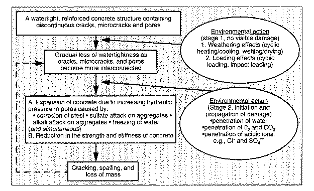
Figure 1-10. A holistic model of concrete deterioration from environmental effects (Mehta 1997).
Preventive Strategies for Controlling Paste Freeze-Thaw Deterioration
Perhaps the most profound discovery concerning the resistance of concrete to freeze-thaw damage was that the entrainment of microscopic air voids could vastly improve the resistance of the paste phase to such damage. As early as the 1930's, deliberate efforts were made to take advantage of this beneficial use of entrained air. Since then, it is standard practice to entrain air voids of the proper size and spacing into the concrete matrix to protect it against paste freeze-thaw damage.
It has been speculated that concrete produced with a w/c below about 0.25 will not require an entrained air system for freeze-thaw durability. Clearly, if the capillary pore system could be entirely eliminated at a low enough w/c, no freezable water would exist in the microstructure. In practice, it is unreasonable to expect to eliminate all capillary pores. Philleo (1983) notes that the combination of self-desiccation, drops in internal humidity with loss of available water, and the statistical non-uniformity of the developing capillary pore system will likely result in some capillary porosity even in very low w/c concrete. Thus, some form of entrained air system is still likely to be needed even for very low w/c concrete.
Air entraining admixtures are specified and tested under ASTM C 260 and C 233. Added to properly proportioned and mixed concrete at established dosage rates, an adequate air void system should be produced. Individual air-entraining admixtures tend to produce characteristic void size distributions regardless of the total volume of entrained air. In general, lower w/c , finer ground cements, finely divided mineral admixtures, and a high proportion of fines in the fine aggregate will typically result in less air entrained in a concrete mixture (Mindess and Young 1981). Because the entrainment of air is the direct result of the mixing action of the mixer, the mixing conditions have a significant impact on the resulting void system. The amount of entrained air initially increases with mixing, but then gradually declines with prolonged mixing.
The air content of fresh concrete can be determined using ASTM C 173 or C 231. Although air content is the parameter typically measured during construction, it alone does not ensure that the air void system in the hardened paste is adequate. Loss of some air during slipform paving is common. Also, the overall air content measurement does not distinguish between entrapped air and entrained air. Recommended air contents for various exposure conditions and maximum aggregate sizes are presented in table 1-8.
In addition to its direct effect on freeze-thaw durability, entrained air affects other properties of fresh and hardened concrete. Entrained air typically improves the workability of fresh concrete and tends to reduce bleeding and segregation. At a constant w/c, the addition of internal air voids will have a detrimental impact on the strength of hardened concrete. For moderate strength concrete, each 1 percent increase in air content tends to reduce compressive strength by about 5 percent. This reduction in strength can be partially offset by a reduction in the w/c made possible by the increased workability of air-entrained concrete. For higher strength concrete, a similar reduction in strength occurs with the addition of air, but it has been shown that with the use of high-range water-reducing admixtures, strength can be maintained by a modest reduction in w/c. When the reduced w/c that is made possible by entrained air is utilized, the sulfate resistance of concrete is also improved because of the resulting reduction in permeability.
If difficulties in obtaining adequate air entrainment have been encountered, the air void system in hardened concrete should be assessed microscopically as part of the mix design and during construction using procedures described in ASTM C 457. The use of automated air void analysis will significantly reduce the time and labor needed to conduct this evaluation. It is currently the only accepted means to determine if the air-void system is adequate to protect the paste from freeze-thaw deterioration.
In situations where direct laboratory testing is desired to establish freeze-thaw performance, ASTM C 666 (Method A) Resistance of Concrete to Rapid Freezing and Thawing, is the most widely used standardized method for accelerated freeze-thaw testing. The method subjects concrete test prisms to 300 cycles of freezing and thawing. Two different procedures are provided in the method: Procedure A, in which both the freezing and thawing of the test specimens occur in water, and Procedure B, in which the freezing of the test specimens occurs in air while the subsequent thawing is in water. ASTM C 666 was created in 1971 by consolidating two different procedures, ASTM C 290 for Procedure A and ASTM C 291 for Procedure B, that had been in use since 1952 (Newlon and Mitchell 1994). In response to criticisms of both these procedures, including concern about possible confining pressures on the specimens created in Procedure A and possible drying of the specimens during freezing in Procedure B, a third procedure has been proposed (Janssen and Snyder 1994). The proposed alternative (termed Procedure C) modifies Procedure B by wrapping the test specimens with absorbent cloth to help keep them wet during freezing. Reduced variability in test results was reported using the proposed Procedure C. Current recommendations, however, are to use Method A (TRB 1999).
Table 1-8. Recommended air contents for freeze-thaw distress resistant concrete (ACI 1992a).
|
Nominal Maximum |
Average Air Content, Percent1 | |
|---|---|---|
|
Moderate Exposure2 |
Severe Exposure3 | |
|
9.5 (3/8) |
6 |
7.5 |
|
12.5 (1/2) |
5.5 |
7 |
|
19 (3/4) |
5 |
6 |
|
25 (1) |
5 |
6 |
|
37.5 (1-1/2) |
4.54 |
5.54 |
|
75 (3) |
3.54 |
4.54 |
|
150 (6) |
3 |
4 |
1A reasonable tolerance for air content in field construction is ±1.5 percent.
2Outdoor exposure in a cold climate where the concrete will be only occasionally exposed to moisture prior to freezing, and where no deicing salts will be used. Examples are certain exterior walls, beams, girders, and slabs not in direct contact with soil.
3Outdoor exposure in a cold climate where the concrete may be in almost continuous contact with moisture prior to freezing, or where deicing salts are used. Examples are pavements, bridge decks, sidewalks, and water tanks.
4These air contents apply to the whole as for the preceding aggregate sizes. When testing these concretes, however, aggregate larger than 37.5 mm (1-1/2 in) is removed by handpicking or sieving and the air content is determined on the minus 37.5 mm (1-1/2 in) fraction of the mixture. (The field tolerance applies to this value.) From this the air content of the whole mixture is computed.
If specimens fail ASTM C 666, petrographic analysis using ASTM C 856 can be used to determine which component of the concrete mixture is responsible so that modifications can be made. This test is more time consuming and labor intensive than ASTM C 457, and therefore is not recommended to test paste freeze-thaw deterioration alone.
Preventive Strategies for Controlling Deicer Scaling/Deterioration
In general, deicer scaling is not a concern for properly constructed, high quality PCC. But even if the concrete is properly constructed and cured, deicers may damage concrete with poor mixture characteristics, or concrete that was improperly finished. Pigeon (1994) comments on this by stating that “air entrainment improves to a very large degree the resistance to deicer salt scaling…and as could be expected, scaling decreases with water-cement ratio, and finishing and curing operations are particularly important.” As indicated, the two primary mix design considerations for producing deicer scaling/deterioration resistant concrete are relatively high cement content (with corresponding low w/c) and air entrainment.
Air content is an important consideration when trying to prevent deicer scaling. Concrete that has adequate air entrainment for protection against freeze-thaw damage may be susceptible to the development of salt scaling. Collepardi et al. (1994) conclude that air contents recommended by ACI for “severe exposure” should be followed if the concrete is to be exposed to calcium chloride deicers, finding that concrete with air contents meeting ACI “moderate exposure” requirements suffered severe degradation in laboratory testing even without being subjected to freeze-thaw action. The ACI recommendations are presented in table 1-8 (ACI 1992a).
One controversial mix design consideration is cement content. Some studies have reported that to produce deicer scaling/deterioration resistant concrete, a relatively high cement content (with corresponding low w/c ) should be used. A recent ACPA (1992) publication states that salt scaling can be prevented if a minimum cement content of 335 kg/m3 and a maximum w/c of 0.45 are used. In earlier work, Woods (1968) recommended that a minimum cement content of 370 kg/m3 be used to prevent scaling. Marchand et al. (1994), in their review of deicer salt scaling, cites a number of studies that show as w/c increases, so does scaling. They found that cement content is not the critical issue, but instead a low w/c with adequate workability to facilitate consolidation is needed. This point is reinforced in a recent publication that states that the practice of specifying a minimum cement content to ensure durability is "obsolete" (TRB 1999).
In addition to the use of entrained air and low w/c , the use of fly ash has been proposed to enhance deicer scaling/deterioration resistance. The PCA (1992) reports that air-entrained concrete containing fly ash has similar freeze-thaw durability to concrete made with portland cement as the sole binder as long as the same compressive strength, air void system, and curing are obtained. The results of a study conducted by Malhotra et al. (1991) agree with those by Malek and Roy (1988) in which it was found that the incorporation of fly ash (two ASTM Type F and one Type C) appreciably reduced the permeability of concrete to chloride ions. This study was based on measuring chloride ion permeability using AASHTO T 277 and not on a measure of scaling resistance. Bilodeau et al. (1991) found that concrete containing up to 30 percent ASTM Type F fly ash generally performed well under the combined effect of freezing and thawing in the presence of salt deicer, although performance of the fly ash concrete was more variable. Although extended periods of moist-curing or drying periods did not seem to significantly affect performance, the use of membrane curing had a decided benefit, particularly for fly ash concrete. In a paper published a year later, Bilodeau and Malhotra (1992) reported on the properties of concrete containing ASTM Type F fly ash as 58 percent of the total cementitious materials content. He noted that, in addition to acceptable mechanical properties, high-volume fly ash concrete had excellent resistance to chloride ion penetration as compared to plain concrete mixes. He mentioned that further testing is needed to demonstrate scaling resistance.
An experiment conducted by Byfors (1987) examined the influence of fly ash and silica fume addition on chloride ion penetration and pore solution alkalinity. It is reported that the addition of either fly ash or silica fume considerably reduces the rate of chloride ion diffusion. Malhotra et al. (1991) cite a number of studies that indicate the incorporation of low calcium fly ash (ASTM Type F) in concrete significantly reduces chloride ion penetration.
In a large laboratory study, Gebler and Klieger (1986) examined the durability of concrete made with both ASTM Type C and Type F fly ash. Both the chloride ion penetration and deicer scaling resistance were measured. It was concluded that fly ash concrete was just as resistant to chloride ion penetration as conventional concrete with similar w/cm. But it was also found that conventional concrete was more scaling resistant than fly ash concrete, regardless of the type of fly ash used.
Marchand et al. (1994), in a review of salt deicer scaling, report that many studies are contradictory concerning the scaling resistance of fly ash concrete. They found that many laboratory studies indicate poor scaling resistance of fly ash concrete, yet field studies show adequate performance. They attribute most of these differences to the variable nature of fly ash and to its slow rate of hydration, concluding that the maximum recommended amount of fly ash should be limited to 30 percent of the total mass of cementitious material.
Detwiler et al. (1994) found that either a 5 percent addition of silica fume or 30 percent addition of slag led to a far greater reduction in chloride ion penetration than did reducing the w/c from 0.5 to 0.4. They also noted that increasing the curing temperature over a range from 23°C to 70°C creates large differences in performance that indicates "the importance of controlling the curing process if durability is to be achieved." Thier findings seem inconsistent with those of Stark and Ludwig(1997), but this may be explained by Malhotra's findings in which concrete containing fly ash actually has lower chloride permeability but still had poor scaling resistance (Malhotra 1991). Obviously, more research needs to be conducted to determine if fly ash and/or GGBFS can be used to improve scaling resistance.
Whiting and Schmitt (1989) developed a model that related surface scaling to various paste parameters for concrete produced using high range water reducers. The published model is reported below:
 (1-7)
(1-7)
where:
SC= The scaling code (from 1 to 5).
![]() =
The Power’s spacing factor, mm.
=
The Power’s spacing factor, mm.
w/c=The water-cement ratio.
VR= The void removal parameter (1 to 5).
This model predicts deicer scaling according to a scaling code (SC), with 1
meaning no scaling observed and 5 being heavy scaling. The model predicts that
SC is reduced by minimizing the Power's spacing factor (![]() ),
by decreasing the w/c , and by decreasing the void removal parameter,
VR. The void removal parameter is a factor that considers the proportionate
variability in the amount of voids that exist in the near surface zone of the
concrete compared to the main concrete mass. It ranges from 1 to 5, with a 1
indicating that no variation in the void structure is apparent and a 5 indicating
complete removal of voids from the near surface zone. Thus, two of the three
factors contributing to scaling are mix related (
),
by decreasing the w/c , and by decreasing the void removal parameter,
VR. The void removal parameter is a factor that considers the proportionate
variability in the amount of voids that exist in the near surface zone of the
concrete compared to the main concrete mass. It ranges from 1 to 5, with a 1
indicating that no variation in the void structure is apparent and a 5 indicating
complete removal of voids from the near surface zone. Thus, two of the three
factors contributing to scaling are mix related ( and w/c ), while the third factor is controlled by construction.
Construction and curing considerations include good finishing practices, adequate curing, and a drying period prior to deicer application. Deicer scaling is more likely to occur in concrete that has been overvibrated or improperly finished, actions that create a weak layer of paste or mortar either at or just below the concrete surface (Mindess and Young 1981). As discussed, this layer consists primarily of paste and is subjected to high hydraulic and osmotic pressures as well as thermal shock upon the application of chemical deicers.
The ACPA (1992) states that the prevention of salt scaling can be accomplished by "providing adequate curing, and providing an absolute minimum of 30 days of concrete 'drying' before applying deicing chemicals." The term "adequate curing" is a matter of some debate. Woods (1968) recommends that periods of moist curing be related to cement type and curing temperature as shown in table 1-9. Interestingly, in Woods' text, the word "moist" is not associated with curing since it is assumed that all curing is moist curing. It is also worth noting that less than 7 days moist curing was not even considered an acceptable alternative.
Table 1-9. Minimum moist curing times for scaling resistance (Woods 1968).
|
Cement Type |
Percent CaCl2 |
Minimum moist curing period, days |
||
|---|---|---|---|---|
|
at 23°C |
at +4°C |
at -4°C |
||
|
I |
0 |
7 |
15 |
over 60 |
|
2 |
7 |
7 |
30 |
|
|
II |
0 |
7 |
12 |
35 |
|
2 |
7 |
7 |
28 |
|
|
III |
0 |
7 |
7 |
24 |
In work conducted by Beaupré and cited by Pigeon and Plateau (1995), it was confirmed that moist curing is very beneficial in minimizing deicer scaling, as determined using the ASTM standard test C 672, with 14 days moist curing being significantly better than 2 days. An interesting finding of this study, and one confirmed by other researchers, is that a 7-day curing period with curing compounds is superior to moist curing. The exact reason for this is unknown, as it was shown that it is not a result of lower chloride ion penetration. Pigeon and Plateau (1995) speculate that it might be due to slowing down the drying process, with a concomitant reduction in surface damage due to drying. How an application of a curing compound can reduce drying to below that which occurs under moist curing is unexplained, as are the uncertainties as to whether this benefit transfers from the laboratory to the field.
Gunter et al. (1987) report that the length of wet curing affects the resulting pore structure, with extended wet curing resulting in a finer, more uniform pore size distribution. This has a positive effect on durability. Interestingly, he found that long periods of curing in water can actually critically saturate voids, decreasing durability to freeze-thaw. Overall, he concludes that only a short duration of curing is required for conventional air-entrained concrete to produce resistance to freezing and thawing and deicer scaling.
Research reported by Tsukinaga et al. (1995) also has some bearing on concrete curing. They studied the effectiveness of permeable sheets used during construction to improve concrete properties. Permeable sheets are relatively new to concrete construction, typically being placed between the formwork and concrete in vertical construction. The permeable sheet allows bleed water to drain down and air to escape upward, densifying the concrete surface. This densification of the surface has positive effects in reducing "bug holes," decreasing the w/c of the surface, increasing strength, reducing permeability, improving freeze-thaw resistance, and decreasing chloride ion penetration. It is uncertain if similar technology would be practical for horizontal flat work or pavement construction. But it is interesting how an improvement of the concrete surface characteristics through modified construction practices can have a profound effect on factors related to durability.
Once a mixture is designed, it is important to determine its deicer scaling resistance. Two test methods are commonly used to investigate the scaling resistance of concrete. The most commonly used test is ASTM C 672 (Mindess and Young 1981). In this test, a CaCl2 solution is ponded on the surface of rectangular concrete specimens that are then subjected to freeze-thaw cycling. The specimens are placed in a freezer (-17.8°C) for 16 to 18 hours and then manually removed to a thawing environment for 6 to 8 hours. A surface layer of the water/salt solution is maintained at all times. A visual inspection is made at 5, 10, 15, 20, 25, and 50 cycles and the concrete is rated on a scale of 0 to 5 (0 is for concrete surfaces showing no sign of scaling and 5 is for a surface that is severely scaled with coarse aggregate visible over the entire surface). The subjectivity inherent in the rating scale is one problem with this test (Pigeon and Plateau 1995). As a result, it is becoming common for researchers to measure the mass of scaled material to gain a more objective measure of scaling resistance.
The Böras method (Swedish Standard SS 13 72 44) is similar to ASTM C 672, but has been modified to more accurately represent field conditions. A freezing front passes from the top of the specimen downward. This test allows for testing of specimens obtained from in situ structures as well as those prepared in the lab. A rating is assigned based on the mass of scaled material. Although similar to ASTM C 672, Pigeon and Plateau (1995) believes that it is a better test for evaluation of scaling resistance. Unfortunately, correlation between laboratory tests and field performance are not very good (Pigeon 1994; Mehta 1991).
In consideration of deicer deterioration at the joint/crack, it is obvious that the potential deterioration mechanisms are not well enough understood that specific material selection or mix design recommendations can be made. The permeability of the concrete clearly has a large impact on this distress type, and thus any changes to mix design that decrease permeability would likely positively impact the resistance to deicer deterioration. Further, it would be advantageous to alter the chemistry of the cementitious materials so that less soluble hydration products are produced. Increased production of calcium silica hydrate (CSH) at the expense of CH would likely be beneficial. Also, a reduction in aluminates may reduce the potential for the formation of calcium chloroaluminates.
Preventive Strategies for Controlling Aggregate Freeze-Thaw Deterioration
The best method of preventing aggregate related freeze-thaw problems is to use aggregates with a demonstrated service record. Aggregates associated with freeze-thaw deterioration are almost always of sedimentary origin (both calcareous and siliceous) or in a few cases sedimentary rocks that have been partially metamorphosed (Stark 1976). Although many sedimentary aggregates have been shown through both laboratory testing and field performance to provide good freeze-thaw durability, those with low bulk specific gravity, a high porosity, and a large number of small pores are often susceptible to freeze-thaw deterioration (Pigeon and Plateau 1995). Aggregates of igneous and metamorphic origin typically have good freeze-thaw performance because of their very low porosity.
Laboratory testing of aggregates for freeze-thaw durability has been generally grouped into two categories (Larson and Cady 1969). In the first group are tests that attempt to predict field performance by simulating the service environment to which the concrete will be exposed. In the second group are tests that are based on correlating an identifiable and measurable characteristic of the aggregate with known field performance.
The first group includes tests that subject aggregate or concrete specimens to various freezing conditions. These include the rapid freezing and thawing of concrete (ASTM C 666) and the critical dilation test (ASTM C 671). Other laboratory tests include the Washington hydraulic fracture test, which attempts to simulate the internal hydraulic pressures experienced during a freezing event by the use of a high pressure chamber, and the Kansas DOT Soundness Test for Aggregates.
Included in the second group are tests that attempt to measure either directly or indirectly some characteristics of the aggregate pore system. These include the Iowa Pore Index test, mercury intrusion porosimetry measurement of pore size and volume, and microscopic characterizations of the pore system. Because the freeze-thaw durability of an aggregate is not an intrinsic property of the aggregate alone, but includes the confining environment of the mortar in which it is contained and the environmental conditions to which it is exposed, it is reasonable to group test procedures by whether they are confined or unconfined.
ASTM 666,Standard Test Method for Resistance of Concrete to Rapid Freezing and Thawing, is the most common laboratory procedure currently used to assess the expected freeze-thaw performance of concrete aggregates. The details of this procedure have already been described. One variation used by both Kansas and Iowa when testing aggregate performance is an extended moist curing time of 90 days (Schwartz 1987). This is to help ensure that the paste phase has time to fully develop before testing. Michigan uses pressure saturation as a pre-treatment of the coarse aggregates prior to casting test specimens to ensure that the aggregates have an opportunity to become critically saturated during the test cycles. Although ASTM C 666 does provide for the calculation of a durability factor, it does not indicate what value of the durability factor is acceptable. A number of agencies have found that increasing the number of test cycles for acceptance from 300 to 350 provides a better distinction between good and poor aggregates (Schwartz 1987). Depending on the length of curing and the number of cycles, this test can take as long as 5 months to complete.
ASTM C 671,Standard Test Method for Critical Dilation of Concrete Specimens Subjected to Freezing, is also called the Powers Slow Cool Test. Concrete test cylinders (75 mm by 150 mm) are kept submerged in water at 1.7°C and every 2 weeks they are placed in water-saturated kerosene and the temperature is lowered at 2.8°C per hour from 1.7°C to -9.4°C. During the cooling cycle, specimen length changes are measured as a function of time. Specimens are then returned to their water bath until the next cooling cycle. The specimen dilation, caused by internal ice formation, is obtained from a plot of the specimen length change versus time. Specimens made with durable aggregates typically exhibit a small dilation that remains nearly constant after many cycles while non-durable aggregates result in large dilation that significantly increases with repeated cycles. A critical dilation is reached, and the specimen is considered significantly damaged when the dilation increases by a factor of two between successive cooling cycles. This procedure does a good job of distinguishing very good durability concrete from very poor durability concrete, but typically does not provide an assessment of marginal concrete that deteriorates slower (Schwartz 1987).
The Washington Hydraulic Fracture test uses a high pressure chamber in an attempt to simulate the hydraulic pressures experienced by aggregates during a freezing cycle (Janssen and Snyder 1994). An unconfined aggregate sample of known size range and number of particles is surface-treated and placed in a pressure chamber filled with water. A pressure of 7930 kPa is applied to the aggregates, forcing the water into the pore system under pressure. The pressure is rapidly released, causing the internal water in the aggregate pore system to be forced back out by the compressed air within the aggregates. Fracturing of the aggregates occurs if the pore pressure is not dissipated quickly or if the internal pressure cannot be elastically accommodated. After 10 cycles of applying and releasing pressure, the aggregate sample is removed, dried, and tumbled in a rock tumbler and graded and counted. This process is repeated 5 times for a total of 50 cycles and a percentage of fractures are used to calculate a hydraulic fracture index. Although this procedure can identify aggregates likely to fail due to hydraulic pressures, it does not simulate the confining effect of the paste phase and cannot identify aggregates that cause paste failure due to excessive water expelled from aggregates.
If aggregate freeze-thaw deterioration is a potential problem as revealed either through experience and/or the results of aggregate testing, preventive measures must be taken. Obviously, the best method of preventing aggregate freeze-thaw deterioration is to reject the use of susceptible or marginal aggregate, and use only aggregate with demonstrated good field performance and/or laboratory testing results. Unfortunately, this is not feasible in many areas where sources of non-susceptible aggregate do not exist or where laboratory test results are ambiguous.
Therefore, if a marginal aggregate source is being considered for use, it must undergo benefaction to reduce the susceptibility to this MRD. To this end, three methods have been used with some success. The first method attempts to separate susceptible aggregate from non-susceptible aggregate using the aggregate bulk specific gravity. It has been found in some cases that aggregates having lower bulk specific gravities are less resistant to freeze-thaw deterioration. This difference can be used to separate aggregate using heavy-media separation (Schwartz 1987). With the elimination of the lighter aggregate particles, the remaining aggregates are considered to be more resistant to freeze-thaw deterioration. Although this method is workable, it is not considered to be the most effective benefaction method.
Another method to improve the freeze-thaw resistance of an aggregate source is to blend it with an aggregate source that is known to be frost-resistant. Blending simply dilutes susceptible aggregate with non-susceptible aggregate, increasing the overall freeze-thaw durability of the concrete. The exact percentage of blending will vary with the aggregate source. Unfortunately, this method is not considered to be very effective, as it has a tendency to simply delay the onset of damage rather than preventing it, although it may reduce the severity of the distress once it occurs (Schwartz 1987).
The third method is to reduce the maximum aggregate size below the critical size needed to cause damage. This method has become standard practice in many highway agencies and overall has been effective in reducing the incidence of aggregate freeze-thaw deterioration. The degree that the aggregate size must be reduced varies with the aggregate type. In many instances, the maximum aggregate size has been reduced to 19.5 mm, and in some cases as small as 12.5 mm. Because of the ease of applying such criteria, it has become common practice in some agencies to specify mixtures having small maximum aggregate size even if the aggregate is not demonstrated to be freeze-thaw susceptible. This practice, although seemingly effective in reducing aggregate freeze-thaw deterioration, has led to a significant increase in the paste requirement for pavement concrete. It also may have detrimental effects on the mechanical behavior of the concrete pavement (particularly in the load transfer efficiency across cracks and non-doweled joints).
With the desire to use a larger maximum aggregate size, the best approach might be to use a combination of blending and size reduction for aggregate benefaction. Aggregate sources with demonstrated susceptibility to freeze-thaw deterioration can be crushed to smaller, non-susceptible sizes, and then blended with larger aggregate obtained from a non-susceptible source. This combination of techniques should provide a good compromise between enhanced durability at minimal additional cost, as only the larger size fractions need to be purchased and shipped.
Regardless of the benefaction method employed, the effectiveness should be assessed in the laboratory prior to construction. It is believed that the laboratory test method must confine the aggregate in a concrete matrix, such as ASTM C 666 and ASTM C 671. Both tests require expensive equipment and considerable time. But these tests can be used to establish the aggregate freeze-thaw resistance in advance of construction, then correlated with a more rapid test such as ASTM C 295.
Preventive Strategies for Controlling Alkali–Silica Reactions
In areas with known ASR problems or if testing of the aggregate indicates that ASR potential exists, preventive measures should be exercised to prevent ASR in the field. Deleterious ASR can be prevented either through the reduction of reactive silica, the lowering of the pH of the pore water, the reduction of available moisture, or through chemically altering the concrete environment. An overview of each of these methods is included below. An excellent resource available to assist in the prevention of ASR is a document entitled,Guide Specifications for Concrete Subject to Alkali-Silica Reactions (PCA 1995). ACI 221.1R-98 also provides a good overview of preventative measures that can be employed to mitigate ASR. Both references provide a detailed description of techniques and test methods that can be used to minimize the risk of suffering deleterious alkali–silica reactions in concrete.
Two methods have recently been put forward to address ASR problems. The proposed Canadian standard, as described by Fournier et al. (1999), considers not only the degree of aggregate reactivity, but also the environment in which it will serve, the level of risk, and the design life of the structure to determine a desired level of prevention. Five different levels of prevention are considered, ranging from "Nothing Special" to "Exceptional Preventative Action Required." Preventative measures range from accepting the aggregate in the case of a "Nothing Special" prevention level to rejecting the aggregate, limiting the total alkalis in the mixture, or using supplementary cementitious materials in the other cases. There is no testing of the mixture specified to verify the effectiveness of the mitigation.
The Proposed AASHTO Guide Specifications (AASHTO 2000) advance a slightly different approach, in which an ASR susceptible aggregate is either rejected or mitigated. Mitigation is absolute in the sense that mixture proportions must be altered until the prevention criteria are met. There is no consideration for level of prevention required (based on risk level and design life). Instead the proposed standard adopts a “zero-tolerance” approach for deleterious ASR, regardless of the pavement’s location or level of service. Thus, concrete used in a local road in a desert would have to meet the same prevention criteria as that going into a multi-lane, urban interstate in a wet-freeze climate. The mitigation techniques considered include the use of low alkali or blended cements, the use of supplementary cementitious materials, or lithium admixtures.
If possible, field performance history is the best method for determining the potential for ASR in concrete mixes. In order to compare field performance of an older mix with potential field performance of a suggested mix, several factors must be considered:
If the answer to all of the above questions is "yes," then the field concrete is representative of the proposed concrete mixture (Farny and Kosmatka 1997; CCAA 1996). Commonly, differences between mixtures placed in the field many years ago and new mixtures make it impossible to base mix design decisions on performance of existing pavements. For this reason, other methods must be used.
One obvious method to prevent ASR is to reject the susceptible aggregate source in favor of aggregate not containing reactive silica. This method is particularly warranted if the aggregate is found to be highly reactive, in which case other preventive treatments may not be effective. But in many cases, this may not be an option as less reactive aggregate sources may not be available. It is also possible to blend aggregate containing reactive silica with non-reactive aggregate, effectively reducing the total amount of reactive silica in the concrete. Limestone "sweetening," for example, entails replacement of up to 30 percent of reactive fine aggregate with crushed limestone, effectively reducing deterioration is some sand-gravel mixes (Farny and Kosmatka 1997). But in some cases, reducing the amount of reactive silica can actually make ASR more severe. Although there is less reactive silica present, the alkali content remains constant and as a result, the alkali content to reactive silica ratio increases, resulting in a more vigorous reaction. Therefore, when using limestone sweetening, the mix should be tested according to ASTM C227 or ASTM C1293 (Farny and Kosmatka 1997).
Collins and Bareham (1987) found that expansion due to ASR was reduced when porous natural or lightweight aggregate replaced limestone in a concrete mix. There was no evidence of the gel filling in the pores of the aggregate. The reduced expansion is believed to be caused by the dilution of the alkalinity in the pore solution, which resulted from water being absorbed into the aggregate. This hypothesis was mildly supported by the ASTM (1990), which pointed out that changes in the reactivity of aggregate can be attributed at times to variations in the aggregate porosity.
Assuming that a marginally reactive aggregate is being considered for use, deleterious ASR can be prevented through the application of a number of preventive strategies. One strategy is to reduce the available alkalis in the pore solution. Typically, the use of low alkali cement having a total alkali content of less than 0.6 percent is considered effective in controlling ASR when used with low to moderately reactive aggregates. If highly reactive aggregates are being used, the low alkali cements have been less effective (Farny and Kosmatka 1997). More importantly, the total alkalis from all sources in the mix should be considered, including not only the cement, but also other concrete constituents including fly ash, aggregate, admixtures, and mixing water. In situations where potentially reactive aggregate must be used, the proposed Canadian standard (Fournier et al. 1999) stipulates that the total alkalis be limited to a maximum of 3.0 kg/m3 Na2Oefor mild prevention to 2.2 kg/m3 and 1.7 kg/m3 Na2Oe for moderate to strong preventative action, respectively.
In hot climatic regions where highly reactive aggregates are present, such as in the southwestern United States, reducing the total alkali content in the concrete may not be adequate. In such cases, one or more additional actions will be required. These include (Gress 1997):
Blended hydraulic cements must conform to ASTM C 595 or ASTM C 1157 to control ASR. If raw or calcined natural pozzolans are being used, ASTM C 618 should be met. It has been found that higher amounts of slag are needed to control ASR than fly ash. Silica fume must conform to ASTM C1240 and is only needed in a small amount (Farny and Kosmatka 1997; CCAA 1996).
High silica fly ash has been found to be effective in reducing expansion due to ASR. It is believed that the cement alkalis are diluted by fly ash having a lower alkali content, some alkalis are bound to the hydration products, and there is a reduction in concrete permeability due to pozzolan behavior of the fly ash (Detwiler 1997). Keck and Riggs (1997) and Sturrup et al. (1983) also believe that the silica component of the fly ash consumes the available alkali in the cement, reducing the level of expansion.
Farny and Kosmatka (1997) believe that simply using a lower w/cm will create a lower relative humidity within the concrete and, as a result, less gel expansion will occur. A low w/cm also reduces the concrete permeability, limiting the movement of alkalis and moisture within the paste.
As previously mentioned, lithium has recently been employed as a concrete additive to reduce ASR expansion (Gajda 1996; ACPA 1993). Lithium ions in the pore solution of the concrete inhibit the formation of soluble ASR gel (Wang et al. 1994). The ability of lithium to inhibit ASR depends on the compound used, addition rate, aggregate reactivity and cement alkalinity (TRB 1999). The proposed AASHTO Guide Specification (AASHTO 2000) provides considerable information on the use of various lithium compounds and recommended addition rates. It has been found that ASTM C1260 is not effective in determining whether lithium compounds are effective (Farny and Kosmatka 1997).
Regardless of the approach being used to mitigate ASR, it is desirable to test the reactivity of the mixture with all constituent materials combined according to the job mix formula. In the proposed AASHTO Guide Specifications, it is suggested that ASTM C 441, ASTM C 1260, and ASTM C 1293 be used to test mixtures containing all the constituent materials proportioned according to the job mix formula to verify mitigation. For each test, expansion criteria are set along with limitations. For example, the expansion limit using ASTM C 1260 is 0.08 percent for metamorphic aggregates and 0.10 for all other aggregates, yet the test can not be used to evaluate the effectiveness of treatment with a lithium compound.
Unfortunately, accelerated tests as documented in the ASTM standards, depend either on using a highly reactive aggregate or a highly alkali environment to shorten the time frame for analysis. For example, ASTM C 441 is commonly used to assess the effectiveness of mineral admixtures or slag in reducing expansion due to ASR, but it does not use the aggregate under consideration (pyrex glass aggregate is used). Farny and Kosmatka (1997) recommend using ASTM C 1260 to determine if fly ash or ground granulated blast furnace slag (GGBFS) are effective in reducing the ASR, but they note that this test cannot be used to judge the effectiveness of reducing total alkalinity or adding lithium compounds to the mixture. In addition, it is noted that the mechanism responsible for the reduction in expansion that occurs in either ASTM C 441 or C 1260 when used to test the effectiveness of GGBFS and/or a pozzolan might not be the same as would occur in the field. This is because the test duration of 14 days is too short for the slag and/or pozzolan to fully react (ACI 1998). In the Canadian standards, it is recommended that a 2-year test be run in accordance with ASTM C 1293 to fully assess the ability of slag and/or pozzolans to mitigate ASR. Research continues to establish correlation between laboratory tests and field performance.
Until correlation between laboratory tests and field performance is established, the best strategy might be to use local experience to develop mitigation strategies that are known to work. This is the approach taken in the proposed Canadian standards, where testing of the combined constituent materials is not done. The approach instead depends on the testing of the aggregates to establish the degree of reactivity, preferably using ASTM C 1293, although ASTM C 1260 results can also be used. Once the degree of reactivity is established, the level of risk can be assigned to determine the level of prevention needed. Preventive measures are then applied accordingly, with no additional testing.
In closing, research into ways to mitigate ASR is continuing. Two new approaches have been recently proposed for mitigating ASR if reactive aggregates will be used. The mitigation techniques focus on limiting total alkalis in the mix, the use of supplementary cementitious materials, or the addition of lithium compounds. Other methods are also available, including aggregate benefaction.
Preventive Strategies for Controlling Alkali–Carbonate Reactions
The surest way to prevent ACR is to screen aggregates. A number of test methods are available for screening, including field performance, petrographic examination, the rock cylinder test, and the concrete prism test (ACI 1998). Petrographic examination of aggregate using ASTM C 295 is a very useful tool in identifying the composition of the aggregates proposed for the mix design. ACR-susceptible aggregate has very characteristic features, namely dolomitic limestones having a fine grained matrix of calcite and clay surrounding rhombic crystals of dolomite. Descriptions of aggregate that may cause ACR are presented in ASTM C 294. Thus, using petrographic examination, a designer can determine if aggregates possess the characteristics necessary for ACR (Farny and Kosmatka 1997).
Physical expansion tests, such as the rock cylinder method (ASTM C 586), allow the potential for expansion of the aggregate to be nominally measured. The test measures the expansion of small cylinders of rock during exposure to sodium hydroxide solution (Ozol 1994). Mingshu et al. (1994) and Farny and Kosmatka (1997) support the use of the rock cylinder method to aid in the assessment of ACR potential. It is not recommended that the rock cylinder method be used as the sole test to judge an aggregate’s potential reactivity, but rather as a supplement to other testing methods (Ozol 1994).
The concrete prism test, ASTM C 1105, was developed specifically for use with carbonate aggregates to evaluate ACR susceptibility. Similar to the rock cylinder method, the concrete prism test measures the expansion potential of carbonate aggregates in a high alkali solution (Farny and Kosmatka 1997; Ozol 1994). Bérubé and Duchesne (1992) and Ozol (1994) believe that the concrete prism method is the best method for testing aggregates for ACR potential. Bérubé and Duchesne think that ACR-susceptible aggregates do not show appreciable expansion when other methods are used, specifically discouraging the use of the Pyrex mortar bar method (ASTM C 441) in determining ACR potential.
Because ACR expansion can be slow, Gillott (1995) suggests the use of field evidence, when possible, to determine the ACR potential of an aggregate. He warns that certain criteria must be met prior to using field evidence as a measure of aggregate reactivity. The same aggregate must be used in the field sample as is used in the proposed mix design. Similarly, the same type of cement (or one with similar alkali content) and mix design (including cement and admixture content and proportions) should be used in the field test. The conditions of exposure of the field concrete and the proposed structure should be similar. Finally, the age of the field concrete should be considered such that the alkali–carbonate reaction must have had time to develop. Ozol (1994) adds that if the structure shows no distress in the field and the alkali content is high enough to cause ACR, the aggregate cannot be characterized as inert until the aggregate size, proportion of reactive aggregates, and moisture availability are also considered.
If a reactive rock source is identified, selective quarrying can be used to isolate reactive rocks so that they are either not used at all or they are used in limited amounts. If potentially reactive aggregate must be used, it is possible to blend them with non-reactive aggregate to limit the potential for deleterious ACR. Farny and Kosmatka (1997) recommend that the reactive aggregate should be limited to 20 percent by volume if either the coarse aggregate or the fine aggregate is reactive. If both the coarse and the fine aggregate are reactive, then only 15 percent by volume of the aggregate used should be reactive. The maximum size of the aggregate also affects its reactivity. The larger the maximum size of the aggregate, the more potential it has to be reactive (ACI 1998).
The use of low alkali cements is far less effective in controlling ACR than ASR. Alkalies are regenerated through the alkali carbonate reactions, and even cement alkali content as low as 0.40 percent can still lead to initiation of this distress (Farny and Kosmatka 1997). This is in contrast to literature cited in ACI (1992), which suggests that the use of low alkali cement will prevent harmful expansion in most cases. The most important cement parameter to consider when potential ACR susceptibility exists is to minimize the total alkali content per unit volume of concrete, and not focus exclusively on the alkali content of the cement (Ozol 1994).
Pozzolans are also not effective in controlling ACR. However, preliminary evidence suggests that lithium-based admixtures appear to control ACR, although little research has been performed to support this finding (Farny and Kosmatka 1997). Thus, the only demonstrated method currently available to prevent ACR is to eliminate or significantly reduce the amount of reactive aggregate.
Preventive Strategies for Controlling External Sulfate Attack
The need for high quality, impermeable concrete is a prerequisite for concrete resistance to external sulfate resistance. Concrete with a low w/cm and high cement factor is consistently recommended, as it will have lower permeability and thus limit the amount of sulfate ions that can diffuse into the concrete to attack it. This requires good workmanship, curing, and a relatively rich mix with a low w/cm. It is thought that air entrainment is beneficial only in that it makes the concrete more workable, so the w/cm ratio can be reduced. Leek et al. (1995) give recommendations for general chemical attack resistance. They recommend that minimizing voids and cracks, ensuring a good bond between aggregate and cementitious paste, minimizing porosity of the paste, and minimizing the paste fraction of the concrete can all improve resistance to chemical attack through decreased permeability. This approach is also advocated by ACI (1992), which reports that good sulfate resistance can only be ensured by reducing the permeability of the concrete through a low w/cm and good curing practices.
The contribution of the cement type and composition to resistance to external sulfate attack has already been discussed at some length. The recommendations made in table 1-10 should be followed when selecting a cement and w/cm for concrete to be used in a sulfate rich environment. Tuthill (1993b) cites the U.S. Bureau of Reclamation in recommending that the soil and soil moisture be tested for sulfates, unless there is a good service record of nearby concrete in the ground. If the groundwater contains up to 1500 ppm of SO3, Type V cement is recommended. If the sulfate concentration is higher, either an extra sack of Type V portland cement per cubic yard or else a 25 percent replacement with fly ash is recommended. If more than 10,000 PPM of SO3 exist, it is recommended to use both additional cement and fly ash replacement.
Table 1-10. Recommendations for normal weight concrete subject to sulfate attack (ACI 1992a).
|
Exposure |
Water Soluble Sulfate1 (SO4) in soil, percent |
Sulfate1 (SO4) in water, PPM |
Cement |
Water-cement ratio, maximum |
|---|---|---|---|---|
|
Mild |
0.00 to 0.10 |
0 to 150 |
— |
— |
|
Moderate2 |
0.10 to 0.20 |
150 to 1500 |
Type II, IP(MS), IS(MS)3 |
0.50 |
|
Severe |
0.20 to 2.00 |
1500 to 10,000 |
Type V4 |
0.45 |
|
Very Severe |
Over 2.00 |
Over 10,000 |
Type V and pozzolan or slag5 |
0.45 |
1Sulfate expressed as SO4is related to sulfate expressed as SO3as in reports of chemical analysis of cement as SO3x 1.2 = SO4.
2When chlorides or other depassivating agents are present in addition to sulfate, a lower water-cement ratio may be necessary to reduce corrosion potential of embedded items.
3Or a blend of Type I cement and a ground granulated blast furnace slag or a pozzolan that has been determined by tests to give equivalent sulfate resistance.
4Or a blend of Type II cement and a ground granulated blast furnace slag or a pozzolan that has been determined by tests to give equivalent sulfate resistance.
5Use a pozzolan or slag that has been determined by tests to improve sulfate resistance when used in concrete containing Type V cement.
Although the C3A content of cement is the most common cement parameter related to external sulfate attack, DePuy (1994) cites some exceptions where low C3A cements have done poorly, and some moderately high C3A cements have had good sulfate resistance. As described, some researchers also believe that C4AF must also be considered. For this reason, the Type V cement has a maximum calculated C3A content of 5 percent and a combined C4AF + 2C3A content that does not exceed 25 percent. Van Aardt and Visser (1985) determined that the alkali content of the cement could also influence the sulfate resistance of concrete. They found that the following ratios give preliminary indications of resistance to sulfate attack when both were satisfied:
|
|
(1-8) |
For Type V cement, ACI allows the sulfate expansion test, ASTM C 452, to be used in lieu of the chemical requirements. If the proposed cementitious binder is a portland cement or a portland cement blended or modified with slag or fly ash, its sulfate resistance can be tested using ASTM C 1012 (DePuy 1994). Mehta (1991) notes that this test cannot simulate the service behavior of concrete and is of limited value in predicting field performance. Stark (1989) reports that in the low and high w/cm mixes, cement type made little difference, but in the intermediate w/cm mixes (0.45 to 0.55), cement type made significant differences.
Concrete with a low w/cm and high cement factor is consistently recommended, as it will have lower permeability that will limit the amount of sulfate ions that can diffuse into the concrete (ACI 1992a; Emmons 1994; Hognestad 1993; Mielenz 1962; Stark 1984). This is confirmed by DePuy (1994), who cites numerous reports stating that high-quality, impermeable concrete is more resistant to sulfate attack. The ACPA (1993) and Mehta (1991; 1997) report that having a high quality concrete with adequate cement, proper thickness, proper curing, and low w/cm is the best protection against sulfate attack, with the composition of the cement of secondary importance. This requires good workmanship, curing, and a relatively high cement content mix with a low w/cm. It is thought that air entrainment is beneficial only in that it makes the concrete more workable, so the w/cm ratio can be reduced. This was confirmed by Tuthill (1993a), who found that air entrainment should not be used for primary resistance to sulfate attack.
Concrete permeability is a key parameter when considering external sulfate attack, with reduced permeability resulting in improved resistance. In one study, Mangat and Khatib (1995) found that air curing at 20°C and 55 percent RH for 28 days provided the best resistance to sulfate attack for both fly ash and ordinary concrete. The dry curing was as effective as replacement of cement with fly ash, silica fume, or slag. They theorized that this might be due to a carbonated layer formed at the concrete surface under the dry curing conditions. However, greater depths of carbonation did not result in greater sulfate resistance in all cases. Mehta (1991) notes that limited carbonation of paste will improve impermeability due to the formation of insoluble calcium carbonate. Yet excessive carbonation in the presence of aggressive CO2 in soft water will increase permeability. Soluble calcium bicarbonate will be formed and leach away, widening the existing microcracks and pores.
The amount of CH in the cement paste has an effect on the sulfate resistance as it is involved in gypsum corrosion. For this reason, pozzolans are effective in improving resistance to sulfate attack in severe sulfate environments where Type V cement alone may not give adequate protection. In these conditions, it is recommended that a Type VP or VS cement be considered. Supersulfated slag cements, if available, are also a potential option.
A tremendous amount of literature is available on the impact of fly ash on sulfate resistance. Klieger and Gebler (1987) found that concrete made with 25 percent replacement of Class F fly ash showed less expansion due to sulfate attack than that made with Class C fly ash. They called those fly ashes with less than 10 percent CaO Class F, and those with greater than 10 percent CaO Class C, although the fly ashes used did not comply with all of the chemical specifications for ASTM C 618-83. Torri et al. (1995) found no deterioration after 2 years with a 50 percent replacement using Class F fly ash. Two fly ashes were used, one ground finer than the other. No difference was found between the two. The fly ashes were mixed in a 400 kg/m3 binder content concrete.
Ellis (1993) cited several studies that showed Class C fly ash usually had a negative effect on sulfate resistance of concrete compared to Type II cement, unless used at levels of 40 to 50 percent of the total cementitious content. Class C fly ash contains relatively high levels of amorphous calcium aluminate, which decreases performance in a sulfate environment. Stark (1989) reported little effect on sulfate resistance from the Al2O3content of fly ash. Class C fly ashes often contain additional crystalline phases such as tricalcium alumininate, lime, and anhydrite, which are sources of alumina, calcium, and sulfate for the sulfate attack (Tikalsky et al. 1992). Additionally, Class C fly ashes have a higher CaO content, which reduces their ability to convert CH to CSH during hydration. The high calcium fly ashes are in themselves cementitious, leaving behind much calcium hydroxide to later react with sulfates. Thus, Class C fly ash generally does not perform well in high sulfate exposure conditions. McCarthy et al. (1989) gave preliminary results indicating that sub-bituminous fly ash with greater than 25 percent CaO was doing very poorly in sulfate tests. Tikalsky et al.(1992) found that Class C fly ashes were detrimental to the sulfate resistance of the concrete tested.
Freeman and Carasquillo (1996) conducted a study involving Class C fly ash and anhydrous sodium sulfate as a chemical admixture during mixing. They found that adding the sodium sulfate in the proper amount reduced the permeability and improved the sulfate resistance of the concrete, making it more resistant than Type II cement.
In summary, Class F fly ash is generally found to be beneficial in improving sulfate resistance, whereas Class C fly ash may actually be detrimental. For these reasons, only high quality, Class F fly ash should be considered for use in improving sulfate resistance of concrete. It is thought that fly ash meeting ASTM C 618 and having less than 10 percent bulk CaO can be used to improve sulfate resistance. Fly ash containing 10 to 25 percent CaO should be tested using the actual materials to be used in the concrete.
The addition of GGBFS also has beneficial effects toward sulfate durability. According to ACI (1987), the substitution of slag reduces the C3A content by reducing the amount of portland cement in the concrete. It also reduces soluble calcium hydroxide in the formation of CSH, compromising the environment required for the formation of ettringite. CSH also forms in pore spaces normally occupied by alkalis and calcium hydroxide, reducing the permeability of the paste. Slag has latent hydraulic and pozzolanic properties, while fly ash has only pozzolanic properties. The clinker and slag reaction creates semi-permeable membranes in the pores between slag or pozzolan and clinker particles, further decreasing permeability (Bakker 1983). Studies have found that the initial permeability of GGBFS blended cements is higher than that of ordinary portland cement, but that with prolonged curing, the GGBFS ultimately has a lower permeability due to long-term hydration (Gowripalan et al. 1993).
DePuy (1994) and ACI (1987) cite studies that also show blended slag concretes have improved sulfate resistance when GGBFS is substituted for at least 50 percent of the cement and when the Al2O3content is limited. If the alumina content of the GGBFS is less than 11 percent, increased sulfate resistance was found regardless of the C3A content of the cement (ACI 1987). Stark (1989), on the other hand, found little significance in the Al2O3content of the GGBFS.
When using pozzolans or supplementary cementitious materials, a comprehensive materials characterization analysis should be done using X-ray diffraction, bulk composition analysis, and analytical glass composition. The glass composition is used with the ternary diagram to determine the reactivity of the glass phase with regard to long-term resistance to sulfate attack. DePuy (1994) gives the following general guidelines for selecting pozzolans that increase sulfate resistance:
The R-factor, first contrived by Dunstan (1980; 1987) and cited in many papers, may be useful in assessing the ability of a fly ash to improve sulfate resistance. It is as follows:
|
| (1-9) |
Fly ashes with R-factors less than 1.5 improved the sulfate resistance of Type II cement, while R-factors over 3.0 were detrimental. Fly ashes between 1.5 and 3.0 had no significant influence on sulfate resistance. Table 1-11 provides an interpretation of the R-factor versus improvement in sulfate resistance (Mangat and Khatib 1995).
Table 1-11. Improvement in sulfate resistance versus the R-factor (Mangat and Khatib 1995).
|
R-factor |
Sulfate Resistance |
|
< 0.75 |
Greatly improved |
|
0.75 to 1.5 |
Moderately improved |
|
1.5 to 3.0 |
No significant change |
|
>3.0 |
Reduced |
Hartmann and Mangotich (1987) provides several problems with the R-value. They state that it cannot be used to predict relative performance of concrete with portland cement only, or the relative performance of different types or brands of portland cement. It also fails to predict the improvement in sulfate resistance observed with some high lime fly ashes. Also, some high R ashes improved resistance beyond some low R ashes, contrary to what had been predicted. McCarthy et al. (1989) also criticize the R-factor, stating that Dunstan recognized that certain chemical compounds, such as C3A, C4A3S, and gehlenite-rich glass were likely part of the problem of sulfate attack, but the R-factor does not measure these. Nor does it measure the alumina content of the fly ash.
In trying to address some of the limitations in the R-factor, Hartmann and Mangotich (1987) created the Oxide Durability Factor (ODF) from results of expansion data on mortar bars. It relates the chemical compositions of the cementitious ingredients. The formula is given as:
|
| (1-10) |
The ODF was found to vary directly with the sulfate durability of the concrete. The ODF was checked against the work of other experimenters and found to be a good predictor of sulfate resistance.
Tikalsky et al. (1992) found that fly ash with a CaO/SiO2ratio less than 0.25 and containing no detectable C3A at a 35 percent volume replacement provided resistance greater than Type II cement alone. Fly ash containing detectable C3A and a CaO/SiO2 ratio greater than 0.6 decreased sulfate resistance. Unfortunately, these limits would eliminate over 90 percent of fly ash available for use in concrete.
The replacement of portland cement with GGBFS also has beneficial effects toward sulfate resistance through the reduction of the C3A content incurred by reducing the amount of portland cement in the concrete. It also reduces soluble calcium hydroxide by increasing the formation of CSH, compromising the environment required for the formation of ettringite. CSH also forms in pore spaces normally occupied by alkalis and calcium hydroxide, reducing the permeability of the paste.
The sulfate resistance of concrete is decreased through the addition of calcium chloride. It therefore should not be added to concrete subjected to severe or very severe sulfate exposure conditions.
Due to variability in the effectiveness of various techniques to improve sulfate resistance, it is important that specific combinations of the cement and pozzolan be tested to verify sulfate resistance. When using pozzolans or GGBFS with Type V cement, the combination to be used should be tested with an accelerated testing procedure. This is because the low alkali content of Type V cements may not activate the pozzolanic ingredients in the blended cements (ACI 1992a). ASTM C 1012 can be used to assess the sulfate resistance of blended cements or cement-pozzolan mixtures.
Unfortunately, assessing the sulfate resistance of concrete is difficult. There is currently no standard ASTM test for assessing the sulfate resistance of specified concrete made using the selected constituent materials and job mix formula. ASTM C 452 evaluates only the sulfate resistance of portland cement and not that of the concrete. ASTM C 1012 is the most commonly recommended test to assess the sulfate resistance of portland cement, blends of portland cement with GGBFS and fly ash, or blended hydraulic cements. Six-month expansion limits of 0.10 and 0.05 percent roughly translate to moderate sulfate resistance and high sulfate resistance, respectively. But it too only tests the resistance of the cementitious materials and not the concrete. Modifications to the standard test methods could be made so that the job specific concrete is tested. This would be particularly useful as mix parameters are considered to be at least as influential as cement chemistry in the sulfate resistance of concrete.
Preventive Strategies for Controlling Internal Sulfate Attack
It is uncertain to what degree internal sulfate attack affects pavements and, as a result, it is difficult to make specific recommendations to prevent it. However, in light of some well-known premature pavement failures that have occurred in recent years (Gress 1997; Moss et al. 1997), it seems prudent to consider internal sulfate attack as a potential problem in pavements. Prevention must focus on the evaluation of the concentration and chemical form of sulfur within constituent materials (cement, aggregate, and admixtures), potentially establishing limits to control this problem. Concrete permeability may also have an influence as a reflection of the ease of transport for various species within the concrete matrix.
For internal sulfate attack, the composition of the cement is potentially an important factor. Sulfate-related deterioration in concrete is generally related to the C3A content of the cement, with more deterioration typically occurring with higher C3A content. Cement with a C3A content of less than 5 percent is typically considered to be sulfate resistant. Type II and III cements containing less than 8 percent C3A have moderate sulfate resistance. Type V cements with less than 5 percent C3A and less than 25 percent [C4AF +2(C3A)] or [C4AF + C2F] and Type III cements with less than 5 percent C3A have high sulfate resistance (ACI 1992a).
Gress (1997) believes that limiting the sulfate content of cement is an extremely important step in preventing potential DEF. To control DEF, he recommends that a maximum sulfate content for cement and cementitious materials be limited to no more than 3 percent, although he admits that this alone may be insufficient to eliminate deleterious DEF. It is desirable to control the C3A content as well, but a set limit is not practical due to an incomplete understanding of the DEF mechanism at this time. Suggested criteria of limiting the C3A/SO3ratio to less than 2.0 to 2.5 are problematic, as it would eliminate a significant number of currently available cements. As a result, Gress concedes that it is impossible at this time to recommend a cement specification to prevent DEF.
ASTM C 1038,Expansion of Portland Cement Mortar Bars Stored in Water, has been used to investigate the expansion of concrete resulting from calcium sulfate (gypsum) in the cement.It is applicable to the study of a specific portland cement and thus cannot be used to consider the influence of aggregate or admixtures. An expansion limit of 0.20 percent at 14 days of water immersion is used in Canadian Standards document CAN 3-A5-M83. Expansion is directly related to the amount of calcium sulfate present in the cement and thus the impact of other sources of sulfate, such as slowly soluble chemical forms of sulfur, would not be evaluated. It is thus not thought to be a reliable indicator of DEF potential. Gress (1997) suggests that a new test method needs to be developed where heat cured mortar bars are made with the proposed constituent materials and length changes are measured over time.
The Duggan Test has been proposed as a test method that provides a “rapid measure of the potential for chemical expansion in concrete”[American Railway Engineering Association (AREA) 1996]. Expansion can be due to AAR, internal sulfate attack, or other potentially deleterious reactions. In this test, 25-mm-diameter concrete cores that are 51 mm in length are subjected to prescribed wetting and dry heat cycles for 10 days. Expansion is routinely measured following the final dry heat conditioning as the specimens soak in distilled water for a period of 3 weeks. Expansion should not exceed 0.15 percent at day 20 according to AREA specifications for concrete railroad ties. Others have suggested that if the expansion exceeds 0.05 percent after the 20 days of water immersion, additional information be gathered to determine if a deleterious chemical reaction is implicated.
The effect of adding fly ash or GGBFS to concrete on the occurrence of DEF is unknown. On the one hand, as discussed previously, pozzolans can increase concrete resistance to sulfate attack. But fly ash and GGBFS may also provide forms of sulfur that may lead to the adverse reaction. Gress (1997) examined the possible role that fly ash may have had in premature pavement deterioration, calling for a suspension of the use of combinations of portland cement and Class C fly ash that have demonstrated early distress unless they can be proven acceptable by additional testing. In addition to identifying Type C fly ash as a possible source of slowly soluble sulfur, Gress also focuses attention on the solubility of the aluminate phases in the fly ash, stating that slowly soluble Al2O3 may become encapsulated within the CSH gel before going into solution. If this occurred, it is speculated that it may react at a later date. He concludes that a study is urgently needed to examine the roles of SO3and Al2O3 found in some fly ash in the development of DEF/EXS in concrete.
Another potential source of slowly soluble sulfate is the aggregate. Sulfates having very low solubility in water, such as barium and lead sulfate, are relatively harmless. But some aggregate sources may contain moderately soluble forms of sulfate that may be problematic. A petrographic analysis of the aggregate, in accordance with ASTM C 295, should be used to identify potentially problematic sources of aggregate sulfates.
Aside from the properties of the constituent materials, the overall quality of the concrete may also impact its susceptibility to internal sulfate attack. Thus, recommendations made regarding the selection of quality materials, the design of a relatively impermeable mix, and the use of proper construction methods should help reduce the potential for internal sulfate attack. Specifically, using mixes with higher aggregate content and reduced heat of hydration while following recommended hot weather concrete placement practices should have a positive impact on the prevention of internal sulfate attack.
In summary, it is currently unclear as to the best approach to prevent internal sulfate attack in concrete pavements, primarily because the distress is not well understood in pavement concrete. It is thought that factors that contribute to external sulfate resistance will also contribute to the prevention of internal sulfate attack, most notably the use of low alumina cements, low calcium pozzolans, and low permeability concrete. Specific to internal sulfate attack is the desire to restrict internal sources of sulfur from cement, aggregate, and admixtures, particularly slowly soluble forms of sulfur. High ambient temperatures during construction also seem to be implicated, especially if a high early strength, high heat of hydration concrete mixture is being used.
Preventive Strategies for Controlling Corrosion of Embedded Steel
Chapter 3 in ACI 222R (1989) provides an excellent description of how to protect new concrete construction against corrosion. The following three general categories of protection are considered:
For pavement construction, the first and last categories are of most practical merit for prevention of corrosion of embedded steel, as the use of protective coatings on load transfer devices and adequate cover over reinforcing steel should be all that is required if properly constructed, high quality concrete is used.
The most effective pavement design factor for resisting corrosion is to provide adequate concrete cover over the embedded steel. In high quality concrete, the carbonation zone is unlikely to exceed 25 mm and thus a concrete cover of 25 to 40 mm is considered adequate for many structures (Mindess and Young 1981). But tests have shown that structures subjected to severe chloride exposure should have a concrete cover of at least 50 mm (Mindess and Young 1981; ACI 1992a; Mehta 1993). Thus, reinforced concrete pavements constructed in areas exposed to chloride-based deicers should use a minimum 50-mm concrete cover. It is noted in ACI 201.2R (1992b) that to achieve the desired 50-mm cover in paving for 90 percent to 95 percent of the reinforcing steel, the specified cover should be 65 mm.
It is important that a high chloride ion concentration not be introduced into the concrete through the constituent materials. One potential source of chloride ions in the constituent materials is the aggregate. In one study cited in ACI 201.2R (1992b), quarried stone, gravel, and natural sands were found to contain chlorides of sufficient quantity that the chloride ion concentration in the concrete exceeded permissible levels. It is noted that chlorides in aggregate are not always available to the corrosion process. Thus, if concrete made with marginal aggregate has had good field performance, higher chloride levels may be tolerated. Calcium chloride accelerator is another internal source of chloride ions and its use should be discouraged if embedded steel is used. The chloride ion concentration of mixing water should also be limited. Calcium nitrite has been found to be an effective corrosion inhibitor as well as an accelerator (ACI 1992a). The nitrite ion chemically interacts with ferric oxides, making them insoluble. This reinforces the passive film, preventing the ingress of chloride ions up to a certain threshold level (PCA 1992). The cost of a corrosion inhibitor can be rather high, adding 8 percent to the cost of concrete (Mehta 1997).
The determination of the chloride ion concentration may be desired since it is an important factor in the corrosion of embedded steel. Chloride ion concentration can be determined using either of two wet chemical analyses. One is used to determine water-soluble chloride whereas the second determines the acid-soluble chloride content. In each case, a concrete specimen is ground to powder, typically using a rotary hammer to avoid the use of cooling fluids. The most common test is the acid solubility test (AASHTO T 260), in which the pulverized concrete is dissolved in nitric acid. The water-soluble method (ASTM C 1218) has seen limited use. For the same concrete, the average chloride content measured by the water soluble method is typically 75 percent to 80 percent of its acid-soluble chloride content (ACI 1989). Chloride content is most often expressed as the chloride ion (Cl– ) present as a percentage of the mass of cement. It is very important that the chloride content being reported is defined according to the method of testing.
The permeability of the concrete to chloride ion penetration can be measured in the laboratory. AASHTO T 259,Resistance of Concrete to Chloride Ion Penetration was a commonly used test method in which concrete prisms are subjected to ponding of a 3 percent sodium chloride solution for 90 days. The chloride ion concentration is then measured at various depths to assess the degree of ingress. Due to the long testing period, a rapid test was devised based on the electrical conductivity of the concrete. This test is designated ASTM C 1202 Electrical Indication of Concrete’s Ability to Resist Chloride Ion Penetration. As discussed previously, it has excellent correlation to the results obtained by AASHTO T 259 for a wide variety of concrete types and qualities (except for concrete made with silica fume) (Perenchio 1994). The rapidity, ease of use, and reliability make this test very attractive when investigating the chloride ion permeability characteristics of concrete. Because of its usefulness, it is recommended that this test be routinely conducted during mix design as an overall assessment of concrete permeability.
Studies cited in ACI 201.2R (1992b) have shown that for similar cover, the level of corrosion successively decreases with decreasing w/cm. For concrete exposed to very severe chloride environments, it is recommended that a w/cm of less than 0.40 be used if possible. In lieu of this, increasing the concrete cover to 100 mm is recommended for cast in place construction in a marine environment having a w/cm of 0.45. Even the most impermeable concrete can become permeable if cracking occurs. These cracks provide easy access, concentrating chlorides, water, and oxygen to form a cell that can initiate corrosion (ACI 1992a).
Torri and Kawamura (1992) studied the effect of pozzolans and supplementary cementitious materials (fly ash, blast-furnace slag, and silica fume) and environmental conditioning on the concrete pore structure and chloride ion permeability. It was concluded that although the pore structure at the surface of concrete containing mineral admixtures was adversely affected by long-term drying, in all cases, mixtures prepared with admixtures had lower chloride ion permeability than comparable mixtures made of ordinary portland cement.
One interesting study concluded that aggregate can be as much as 1,000 times more permeable than a high quality portland cement paste and thus an overabundance of aggregate may adversely affect the ability of the concrete to protect steel (Perenchio 1994). It is therefore suggested that the maximum aggregate size and aggregate permeability are important considerations when designing against corrosion. Perenchio states that the use of large coarse aggregate particles may in effect “short-circuit” the concrete cover by providing a more direct route for harmful agents to permeate into the concrete. This should be studied in detail before adopting new gradation requirements.
Even the most impermeable concrete can become permeable if cracking occurs. Thus, sound design practices should be used to minimize cracking and to keep cracks that form in reinforced pavements tight, minimizing the infiltration of deleterious agents. Construction practices should be used that prevent plastic shrinkage cracking of the pavement surface through the application of an approved curing compound at the appropriate time. This is most important during dry, windy days when the evaporation of bleed water can be quite rapid. Poor concrete consolidation must also be avoided through the design of a workable mix and care in selecting the appropriate depth, spacing, and operating frequency for internal vibrators.
In rare cases, it may be determined that an existing concrete pavement is at risk of suffering widespread corrosion before active corrosion has actually taken place. For example, a pachometer survey conducted soon after construction may reveal that the steel was improperly placed and adequate cover does not exist. In such a case, an agency may want to take preemptive measures to prevent the future occurrence of corrosion. Various concrete coatings and sealers are available that will prevent or slow down the penetration of water and salts. Silanes in particular have been found to be very effective.
Concrete cover cannot protect dowels and tie bars because the opening at the joint interface allows for the inflow of chlorides, moisture, and oxygen. It is therefore common practice to protect dowels and tie bars from corrosion by using a protective barrier coating such as fusion bonded epoxy. The long-term effectiveness of epoxy coating of embedded steel is currently under intense study (Mehta and Monteiro 1993) although many cite it as an excellent preventive measure Perenchio (1994). Some agencies have investigated the use of plastic and stainless steel cladding as an alternative coating for dowel bars.
This section presents a summary of the approach adopted in the guideline provided in Volume 2 of this Final Report for the prevention of MRD in concrete pavements. The strategy taken applies the background information presented in the previous section to develop a more holistic approach, relying on the selection of constituent materials, proportioning, testing, and construction to ensure that concrete durability is achieved. The guideline concludes with specific recommendations provided for the mitigation of specific MRD types.
Constituent Materials Selection for Preventing MRD
The guidelines espouse the philosophy that quality concrete can only be produced from quality materials. Constituents are broken down into aggregates, cementitious materials,admixtures, and mixing water. An approach is provided to assist the engineer/mix designer in the selection of the various constituents. In the case of aggregate selection, a flowchart has been developed that presents a series of standardized tests that can be used to evaluate aggregate sources for all common aggregate-related MRDs. It is recognized that many agencies have developed their own approaches for evaluating aggregates, commonly focusing on a single distress mechanism. For example, numerous procedures have recently been developed to evaluate the ASR susceptibility of an aggregate source, including the proposed AASHTO Guide Specification (AASHTO 2000) and the new Canadian Standards (Fournier et al 1999). In the guidelines, each agency is encouraged to evaluate its procedures and modify them as necessary to include methods that best address local conditions.
The first step in applying the flowchart is to evaluate the field performance of the aggregate source under study.If the field performance has been poor, it is recommended that the aggregate source be rejected until a thorough analysis can be conducted to determine what, if any role, the aggregate played in the noted failures. Good field performance does not immediately result in aggregate acceptance, as changes in other concrete constituents, mix design, or service conditions could result in deterioration in marginal aggregates that may not have shown up in previous applications. Instead, it is recommended that ASTM C 295 be conducted to characterize the aggregate source to identify whether the aggregate is potentially non-durable, based on susceptibility to AAR or freeze-thaw deterioration, or whether unstable minerals are present. If the aggregate is considered durable, it is approved for use in concrete. Potentially non-durable aggregates undergo testing as recommended. If it is concluded that the aggregate is indeed potentially non-durable in one or more categories, the guideline user is directed to either reject the source or mitigate according to recommendations provided.
Based on the aggregate selected, recommendations are made regarding the type of cementitious materials to be used. The selection of cement and supplementary pozzolanic/cementitious material is an extremely important element in designing durable concrete pavements. In many applications, the use of a standard ASTM C 150 Type I cement will provide satisfactory results, but this is not always the case. The proposed guideline details the selection of cements identified through ASTM C 150, Standard Specification for Portland Cement, and ASTM C 595M,Standard Specification for Blended Hydraulic Cements. Fly ash, GGBFS, and silica fume additives are also discussed with the emphasis on enhancing concrete durability.
Type I cement is most commonly used, although Type III cements are finding more widespread use in "fast-track" projects. In addition, ASTM C 595M provides standard specifications for blended hydraulic cements that feature an intimate blend of portland cement with fine materials such as GGBFS, fly ash or other pozzolans, hydrated lime, and pre-blended cement combinations of these materials (PCA 1992). Blended cements have not been commonly used on paving projects in the United States, but may offer some advantages in producing durable concrete pavements.
Some believe that the movement toward quicker setting cement and faster construction may be detrimental to long-term concrete durability. Mehta (1997) argues that for concrete to remain durable, it must remain relatively impermeable. He proposes that durable concrete should be slow-hardening with high creep and low elastic modulus at early ages to resist drying shrinkage and thermal cracking. Although he acknowledges that this can be accomplished through the use of coarser ground cement with relatively low C3S content, he doesn’t directly advocate a return to the cement of the past. He instead suggests that there is currently an overemphasis on speed of construction that has resulted in the unnecessary use of high early strength mixtures.
The proposed guidelines build on this theme, suggesting that instead of routinely using high cement content mixtures containing Type I or Type III portland cement, lower cement content mixtures containing blended cements should be considered. The lower heat of hydration and denser, less soluble microstructure will produce less permeable, more durable concrete. This would necessitate a major change in the way concrete quality is judged; possibly shifting strength requirements to 56 days or 90 days instead of the 28 days currently used. But, the use of slower setting concrete mixtures may be practical for many paving projects where speed is not paramount.
Cement requirements may also exist depending on the environment in which the pavement will serve. For example, if the pavement will be exposed to sulfates (a common impurity in deicing salts), a Type II or V cement is recommended (ACI 1992a). For very severe exposure, a Type V with added pozzolan or slag with a demonstrated ability to improve sulfate resistance must be used. Additionally, ACI reports that reducing the permeability of the concrete through the use of a low w/cm and good curing practices is also needed to ensure good sulfate resistance. The inclusion of a low calcium pozzolan (e.g., Class F fly ash) or GGBFS also has a beneficial effect by reducing the permeability of the paste while minimizing the amount of soluble CH present. Further, the use of such supplemental cementitious materials can have a positive effect by mitigating ASR as is discussed later in the guideline. In general, it is evident that fly ash and GGBFS can be powerful and cost-effective allies in producing durable concrete through physical and chemical modification to its microstructure. The addition of low calcium fly ash or GGBFS will reduce concrete permeability while converting soluble CH into less soluble, more stable CSH. It is important to demonstrate the ability of the fly ash or GGBFS to mitigate ASR and increase sulfate resistance through standard tests such as ASTM C 227 and C 1293 for ASR and ASTM C 1012 for sulfate resistance.
Non-cementitious admixtures are commonly added to concrete mixtures during proportioning or mixing to enhance the freshly mixed and/or hardened properties of concrete. The guideline describes various admixtures that have been used in pavement construction in North America including air entrainers, water reducers, accelerators, retarders, corrosion inhibitors, non-cementitious minerals, and ASR inhibitors. The user of the guideline is directed to excellent descriptions of these various admixtures that can be found in a number of sources (PCA 1992; Mehta and Monteiro 1993; Mindess and Young 1981). All of these have been discussed in the previous section of this report. Obviously manufactures’ guidelines must be followed when using admixtures and testing must be completed on the job mix to avoid unexpected interactions between multiple admixtures. The final mix constituent considered in the guidelines is the mixing water. Recommendations for water quality are presented based on the standards contained in ASTM C 94.
Considerations in Proportioning and Mix Design for Prevention of MRD in Concrete Pavements
To this point, the guideline has considered the properties of the individual constituent materials of a concrete mixture. Once the materials are selected, they must be economically combined to form concrete that is workable and easy to consolidate, develops adequate strength, and has long-term durability. The PCA (1992) and the ACI (1991) both present acceptable methods for proportioning concrete mixtures. The discussion presented in the guideline focuses exclusively on elements of the proportioning and mix design process that have a direct bearing on enhancing concrete durability.
The key to durable concrete is the use of high quality materials arranged in a dense, relatively impermeable matrix. The selected aggregates should be strong and not be reactive or susceptible to frost or moisture damage within the environment in which they serve. If this condition is met, the hydrated cement paste is the weak link in the matrix, and thus the goal of proportioning aggregates is to ensure that they occupy as high a percentage of the concrete volume as possible. The hardened paste microstructure should be free of microcracking, possess a fine pore structure with an adequate air void system to protect it from freeze-thaw damage, and be composed of hydration products that are dense, stable, and relatively insoluble. Steel must be protected through adequate cover, and the concrete must be properly cured and free of drying shrinkage cracking. The guideline presents specific requirements for the selection of concrete mixture characteristics, aggregate grading, and tests for fresh and hardened concrete that have a bearing on concrete durability as discussed below.
As discussed previously, the w/cm is probably the single most important factor in this regard. It is recommended that the w/cm not exceed 0.45 for pavements that will experience freezing and thawing in a moist environment and will be exposed to deicer applications. In the same environment, reinforced concrete pavements should be constructed with a maximum w/cm of 0.40 unless an additional 12.5-mm of concrete cover is used (ACI 1991). Recommendations regarding exposure are presented in table 1-10 (ACI 1992a). It is generally not recommended that a w/cm exceeding 0.50 be used in pavement concrete.
As discussed in the Transportation Research Circular (TRB 1999), to ensure that an economical, high quality concrete mixture is obtained, the amount of cementitious material used should be minimized while maintaining the required w/cm. This can only be accomplished through a reduction in water content.Steps that can be used to achieve this outcome include the use of (TRB 1999):
Once the w/c and cement content are selected, the physical characteristics of the aggregate must be considered. The two aggregate characteristics that have the largest impact on proportioning are the particle size distribution (i.e., gradation) and the nature of the particles (e.g., shape, porosity, and surface texture) (PCA 1992). These two parameters affect both the handling of fresh concrete and the properties of hardened concrete.
Traditional aggregate grading methods use a coarse aggregate and a fine aggregate as presented in ASTM C 33,Standard Specification for Concrete Aggregates. Both the ACI and PCA procedures recommend that the largest practical aggregate size be used for job conditions to maximize economy while minimizing void space and paste requirements. This is in contrast to recent pavement construction practice that has significantly decreased the maximum aggregate size, particularly in northern midwestern States. The use of smaller aggregate is in direct response to the inadequate freeze-thaw durability of some aggregate sources, but it has become standard practice in some States for all paving concrete, regardless of the specific aggregate’s durability. It is recommended in the guidelines that this practice be reconsidered and that larger aggregate sizes be used if freeze-thaw durability is demonstrated. Blending of larger durable aggregates with smaller aggregates that have been crushed to enhance durability is on recommendation.
The use of a larger maximum aggregate size is one method to increase the proportion of aggregate in the mixture. A second method is to achieve a more continuous aggregate grading than is commonly used in traditional mix design methods. The U.S. Air Force has recently changed its specification for grading aggregates in concrete mixtures, considering both the coarseness and workability of the gradation (Muszynski et al. 1997). Aggregate is no longer considered to be either fine or coarse, but instead is treated as a single aggregate blend. Using these procedures, the Air Force believes that a more easily constructed, better performing concrete pavement is obtained. This approach is advocated in the recent Transportation Circular on concrete durability, which states that a lack of mid-sized aggregate (around 9.5 mm size) results in concrete with high shrinkage, high water demand, and poor workability (TRB 1999). Blending of multiple aggregate sources can be used to address this problem (Shilstone 1990).
It is believed that the use of the largest maximum aggregate size (considering freeze-thaw durability of the aggregate) with a more continuous grading may provide an opportunity to meet these goals. Additional research needs to be conducted on the constructability and performance of such mixes before significant changes to traditional proportioning schemes can be recommended.
Once the mixture proportions have been established, a number of standard tests are recommended that can be used to establish the susceptibility of concrete to MRD. Unfortunately, as discussed previously, many of these standards are designed to test only a single mix constituent, and not the mixture as a whole. Further, many of the tests are long term and are not well suited to mix design process. But even with these limitations, the guideline recommends the following standard test methods that may prove to be useful in assessing the potential durability of pavement concrete:
The guideline recognizes that the current suite of standard tests is limited and that research is currently under way to develop better predictive tests in the future.
Construction Considerations for Preventing MRD
Once a mixture design has been accepted, the next step is construction. Construction can have a very important impact on the occurrence of MRD in concrete pavements, and it is essential that the mixture be properly batched, mixed, consolidated, and cured under conditions that will produce little microcracking and stable hydration products. The guideline addresses the following construction practices that have a direct impact on concrete pavement durability:
The guideline discusses each of these topics, providing guidance that should be followed to ensure that construction does not negatively impact concrete pavement durability.
Controlling Specific Types of MRD
The final section of the guideline presents techniques that can be employed to prevent specific types of MRD in concrete pavements. An SHA that has had specific problems regarding one or more MRD types can use this section to examine what preventive strategies are available to avoid future occurrences. In addition, if the selection of constituent materials indicates that the aggregate source is ASR susceptible, the user of the guideline can turn to this section to find approaches to prevent ASR. This following provides a brief summary of the guidance provided in this section.
Paste Freeze-Thaw Deterioration
The only practical technique available to avoid paste freeze-thaw damage in a freeze-thaw environment is to entrain air voids of the proper size and spacing into the concrete matrix. Air-entraining admixtures are specified and tested under ASTM C 260 and C 233 and the air content of fresh concrete is determined using ASTM C 173 or C 231. It is noted that the measurement of overall air content does not separate entrapped air from entrained air, nor does it ensure that the air-void system in the hardened paste is adequate. Further, loss of air during slip form paving is not uncommon. For these reasons, if a SHA has been suffering paste freeze-thaw damage, the air-void system in hardened concrete should be assessed microscopically during mix design and as part of the construction process using procedures described in ASTM C 457.
Deicer Scaling/Deterioration
In general, deicer scaling is not a concern for high quality PCC that has been properly constructed. In general, it has been found that using a high cementitious content and a low w/cm (0.45 or less) will result in good scaling resistance (assuming proper finishing and curing). In addition, if fly ash or GGBFS are being used, a longer than normal curing period prior to deicer application must be implemented, favoring spring/early summer construction over fall. Testing using ASTM C 672 can be used to assess the deicer scaling potential of a concrete mixture.
Aggregate Freeze-Thaw Deterioration
If aggregate freeze-thaw deterioration is a potential problem as revealed either through experience and/or the results of constituent testing, preventive measures must be taken. The guideline states that the best method of preventing aggregate freeze-thaw deterioration is to reject the use of susceptible or marginal aggregates, and use only aggregates with demonstrated good field performance and/or laboratory testing results. But this is not a practical solution in many areas where sources of non-susceptible aggregate do not exist or where laboratory test results are not definitive.
Therefore, if a marginal aggregate source is being considered for use, it must undergo benefaction to reduce the susceptibility to this MRD. To this end, four potential methods are suggested to improve aggregate freeze-thaw resistance. The first method attempts to separate susceptible aggregate from non-susceptible aggregate using the aggregate bulk specific gravity. The second method is to blend the susceptible aggregate source with an aggregate source that is known to be frost-resistant. Blending simply dilutes susceptible aggregate with non-susceptible aggregate, increasing the overall freeze-thaw durability of the concrete. Unfortunately, this method is not considered to be very effective, as it has a tendency to simply delay the onset of damage rather than prevent it. The third method is to reduce the maximum aggregate size below the critical size needed to cause damage. This method has become standard practice in many States and overall has been effective in reducing the incidence of aggregate freeze-thaw deterioration. This practice, although seemingly effective in reducing aggregate freeze-thaw deterioration, has led to a significant increase in the paste requirement for pavement concrete and has compromised the structural integrity of cracks and joints relying on aggregate interlock for load transfer. The final approach is to combine the second and third, using a combination of blending and size reduction for aggregate benefaction. Aggregate sources with demonstrated susceptibility to freeze-thaw deterioration can be crushed to smaller, non-susceptible sizes, and then blended with larger aggregate obtained from a non-susceptible source. This will provide the best performance at minimal additional cost, as only larger size fractions need to be purchased and shipped.
Regardless of the benefaction method employed, the effectiveness must be tested in the laboratory prior to construction. It is believed that the test method must confine the aggregate in a concrete matrix, such as in ASTM C 666 (Method A)and ASTM C 671.The results of this testing should be correlated with a more rapid test such as AASHTO T-103 or ASTM C 295 to monitor consistency of the aggregate source or the Washington Hydraulic Fracture Test for use in construction control.
Alkali–Silica Reaction
In areas with known ASR problems or if testing of the aggregate indicates that ASR potential exists, preventive measures should be exercised to prevent ASR in the field. The guideline discusses two methods that have recently been put forward to address ASR problems: the proposed Canadian standard (Fournier et al. 1999)and the Proposed AASHTO Guide Specifications (AASHTO 2000). Both these methods have been discussed previously in this report, so they will not be reviewed again, but the emphasis is on eliminating or minimizing the use of ASR susceptible aggregate, limiting alkalis in the concrete, using pozzolans and/or GGBFS, or adding an ASR inhibiting admixture.
Regardless of the approach used, a variety of mitigation techniques are available to address ASR. One obvious method is to reject the aggregate source in favor of aggregate not containing reactive silica. Another option is to blend aggregate containing highly reactive silica with non-reactive aggregate, effectively reducing the total amount of reactive silica in the concrete. Other methods of aggregate benefaction include selective quarrying, heavy media separation,washing and scrubbing, and chemical treatment, all of which may have applicability in some cases (ACI 1998). If the potentially deleterious aggregate supply must be used for practical reasons, other mitigation techniques can be employed in combination with aggregate benefaction.
The most common approach to mitigation of ASR is to reduce the available alkalis in the pore solution. Typically, the use of low alkali cement is considered effective in reducing the total alkalis in the mixture, although using a high cement content may still result in ASR even if a low alkali cement is used. Other potential sources of alkalis include chemical admixtures, pozzolans, slag, aggregate, and mixing water, and the contribution of all of these must be summed with that from the cement to determine the total alkali content of the mix. In the proposed Canadian standard (Fournier et al. 1999), the total alkalis are limited to a maximum of 3.0 kg/m3 Na2Oe for mild prevention to 2.2 kg/m3 and 1.7 kg/m3 Na2Oe for moderate to strong preventative action, respectively. In addition to limiting alkalis, the use of other mitigation techniques may be necessary, including (Gress 1997):
The use of lithium-based additives is showing increasing promise. A number of lithium compounds are available for mitigation, with their effectiveness dependent on the compound used, addition rate, aggregate reactivity and cement alkalinity (TRB 1999). The proposed AASHTO Guide Specification (AASHTO 2000) provides considerable information on the use of various lithium compounds and recommended addition rates.
Regardless of the approach being used to mitigate ASR, it is desirable to test the reactivity of the mixture with all constituent materials combined according to the job mix formula. In the proposed AASHTO Guide Specifications, it is suggested that ASTM C 441, ASTM C 1260, and ASTM C 1293 be used to test mixtures containing all the constituent materials proportioned according to the job mix formula to verify mitigation. For each test, expansion criteria are set along with limitations. In the Canadian standards, it is recommended that a two-year test be run in accordance with ASTM C 1293 to fully assess the ability of slag and/or pozzolans to mitigate ASR. The guideline notes that research continues to be done to establish correlation between laboratory tests and field performance, but until correlation between laboratory tests and field performance are established, the best strategy might be to use local experience to develop mitigation strategies that are known to work.
Alkali–Carbonate Reactions
The surest way to prevent ACR is to screen aggregates prior to use, rejecting those that are potentially susceptible to ACR. If potentially reactive aggregates must be used, it is possible to blend them with non-reactive aggregates to limit the potential for deleterious ACR. The maximum size of the aggregate also affects its reactivity, with aggregate having a larger maximum size having the greater potential for deleterious reactivity (ACI 1998).
The use of low alkali cements is far less effective in controlling ACR than ASR, as even cement alkali content as low as 0.40 percent can still lead to initiation of this distress (Farny and Kosmatka 1997). The most important cement parameter to consider when potential ACR susceptibility exists is to minimize the total alkali content per unit volume of concrete, and not focus exclusively on the alkali content of the cement (Ozol 1994).
Pozzolans are also not effective in controlling ACR. However, preliminary evidence suggests that lithium-based admixtures appear to control ACR although little research has been performed to support this finding. Thus the only method currently available to prevent ACR is to eliminate or significantly reduce that amount of reactive aggregate.
External Sulfate Attack
The guideline presents the need for high quality, impermeable concrete as a prerequisite for concrete being resistant to external sulfate resistance. Concrete with a low w/cm and high cement factor is consistently recommended, as it will have lower permeability and thus limit the amount of sulfate ions that can diffuse into the concrete to attack it. This requires good workmanship, curing, and a relatively rich mix with a low w/cm.
Many researchers have found a link between cement properties and resistance to external sulfate attack. ACI (1992) makes specific recommendations regarding not only the selection of the w/cm,but also the type of cement to be used in an aggressive sulfate environment. These recommendations were previously presented in table 1-10. In moderate to severe exposure levels, a Type II or V cement is required. Cement low in tricalcium aluminate (C3A) should be used if sulfate attack is anticipated, and some researchers state that the aluminoferrite phase (C4AF) of portland cement should also be limited. For this reason, the Type V cement has a maximum calculated C3A content of 5 percent and a combined C4AF + 2C3A content that does not exceed 25 percent. It is recommended that performance testing using ASTM C 452 and C 1012 should be considered to examine the sulfate resistance of portland cements and combinations of cements and pozzolans/slag, respectively.
For very severe exposure, a Type V with added pozzolan or slag having a demonstrated ability to improve sulfate resistance must be used. In these conditions, it is recommended that a Type VP or VS cement be considered. Supersulfated slag cements, if available, are also an option.
Class F fly ash is generally found to be beneficial to sulfate resistance, whereas Class C fly ash may actually be detrimental. For these reasons, high quality Class F fly ash should be considered most useful in improving sulfate resistance of concrete. It is thought that fly ash meeting ASTM C 618 and having less than 10 percent bulk CaO can be used to improve sulfate resistance. Fly ash containing 10 to 25 percent CaO should be tested with the actual materials to be used in the concrete. The replacement of portland cement with GGBFS also has beneficial effects toward sulfate resistance through the reduction of the C3A content incurred by reducing the amount of portland cement in the concrete. It also reduces soluble CH in the formation of CSH, altering the environment required for the formation of ettringite. CSH also forms in pore spaces normally occupied by alkalies and calcium hydroxide, reducing the permeability of the paste.
Due to variability in the effectiveness of various techniques to improve sulfate resistance, it is important that specific combinations of the cement and pozzolan be tested to verify sulfate resistance. Unfortunately, assessing the sulfate resistance of concrete is difficult as there is currently no standard ASTM test for assessing the sulfate resistance of specified concrete made using the selected constituent materials and job mix formula. ASTM C 1012 is the most commonly recommended test to assess the sulfate resistance of portland cement, blends of portland cement with slags and fly ash, or blended hydraulic cements. But it only tests the resistance of the cementitious materials and not the concrete. Modifications to the standard test methods could be made so that the job-specific concrete is tested. This would be particularly useful as mix parameters are considered to be at least as influential as cement chemistry in the sulfate resistance of concrete.
Internal Sulfate Attack
The guideline recognizes that it is uncertain to what degree internal sulfate attack affects pavements and, as a result, it is difficult to make specific recommendations to prevent it. But it also recognizes that in light of some well-known premature pavement failures that have occurred in recent years, it seems prudent to consider internal sulfate attack as a potential problem in pavements. Prevention must focus on the evaluation of the concentration and chemical form of sulfur within constituent materials (cement, aggregate, and admixtures). Concrete permeability may also have an influence as a reflection of the ease of transport for various species within the concrete matrix.And avoiding excessively high curing temperatures is also necessary.
As with external sulfate attack, the composition of the cement is potentially an important factor for internal sulfate attack. Sulfate-related deterioration in concrete is generally related to the C3A content of the cement and, to some degree, the C4AF content as well. Gress (1997) stated that limiting the sulfate content of cement is an extremely important step in preventing potential DEF. To control DEF, he recommends that a maximum sulfate content for cement and cementitious materials be limited to no more than 3 percent, although he admits that this alone may be insufficient to eliminate deleterious DEF.
The Duggan Test has been proposed as a test method that provides a "rapid measure of the potential for chemical expansion in concrete" (AREA 1996). Expansion can be due to alkali–aggregate reactivity, internal sulfate attack, or other potentially deleterious reactions. As a result, petrographic information should be gathered to determine what deleterious chemical reaction is implicated in the expansion.
ASTM C 1038, Expansion of Portland Cement Mortar Bars Stored in Water, has been used to investigate the expansion of concrete resulting from calcium sulfate (gypsum) in the cement. It is applicable to the study of a specific portland cement and thus cannot be used to consider the influence of aggregate or admixtures.
The effect of fly ash or GGBFS on the occurrence of DEF is unknown. On the one hand, as discussed previously, pozzolans can increase concrete resistance to sulfate attack. But fly ash and GGBFS may also provide forms of sulfur that may lead to the adverse reaction by providing slowly soluble forms of sulfate. Another potential source of slowly soluble sulfate is the aggregate. Sulfates having very low solubility in water, such as barium and lead sulfate (which are common in some aggregates), are relatively harmless. But some aggregates may contain moderately soluble sources of sulfate that may be problematic. For instance, work published by Peterson et al (1999) found that calcium sulfide in slag coarse aggregate was soluble at pH levels common in concrete. A petrographic analysis of the aggregate, in accordance with ASTM C 295, should be used to identify potentially problematic sources of aggregate sulfates.
Aside from the properties of the constituent materials, the overall quality of the concrete may also affect its susceptibility to internal sulfate attack. Thus, recommendations made in the guidelines for the selection of quality materials, the design of a relatively impermeable mix, and the use of proper construction methods should help reduce the potential for internal sulfate attack. Specifically, using mixes with higher aggregate content and reduced heat of hydration while following recommended hot weather concrete placement practices should have a positive impact on the mitigation of internal sulfate attack of the concrete.
Corrosion of Embedded Steel
When considering the corrosion of embedded steel, the permeability of the concrete to chloride ion penetration is an important factor in determining whether the cover is adequate. This can be measured in the laboratory using ASTM C 1202, Electrical Indication of Concrete’s Ability to Resist Chloride Ion Penetration. The rapidity, ease of use, and reliability make this test very attractive when investigating the chloride ion permeability characteristics of concrete. Because of its usefulness, it is recommended that this test be routinely conducted as part of the mix design process as a tool to assess concrete permeability, as long as its limitations are recognized.
The guidelines recognize that even the most impermeable concrete can become permeable if cracking occurs. Thus, sound design practices are suggested to minimize cracking and to keep cracks that form in reinforced pavements tight, minimizing the infiltration of deleterious agents. Construction practices should be used that prevent plastic shrinkage cracking of the pavement surface through the application of an approved curing compound at the appropriate time. This is most important during dry, windy days when the evaporation of bleed water can be quite rapid. Poor concrete consolidation must also be avoided through the design of a workable mix and care in selecting the appropriate depth, spacing, and operating frequency for internal vibrators.
Concrete cover cannot protect dowels and tie bars because the joint interface allows for the inflow of chlorides, moisture, and oxygen. It is therefore common practice to protect dowels and tie bars from corrosion using a protective barrier coating such as fusion bonded epoxy. The long-term effectiveness of epoxy coating of embedded steel is currently under intense study although many cite its use as an excellent preventive strategy. Some States have investigated the use of plastic coatings and stainless steel cladding as alternative coatings for dowel bars.
Need for Record Keeping
The final section in the guideline strongly suggests that information collected prior to and during construction regarding the selection of materials, mixture design, and construction practices be collected and stored to assist in future investigations of MRD in concrete pavements. Due to the complexity of the deterioration mechanisms, and to some degree the lack of accurate data from in-service concrete pavements, there is some uncertainty regarding the prevention of many MRD types. SHAs are therefore encouraged to maintain detailed records consistent with ACI 126.1R,Guide to a Recommended Format for the Identification of Concrete in a Materials Property Database. This guide provides the required forms and examples of how to complete them. SHAs are highly encouraged to collect such data, as the use of a standardized data collection format by all SHAs will provide a unique opportunity for researchers to examine MRD occurrences over a wide geographical area. This will assist in answering some of the unknowns that currently exist in the understanding of deterioration mechanisms, ultimately leading to improvements in concrete pavement performance.
Summary of the Techniques for the Treatment, Rehabilitation, and Prevention of MRD in Concrete Pavements
This section of the final report described the background used to develop treatment, rehabilitation, and prevention strategies to address MRD in concrete pavements. Although a number of treatment and rehabilitation strategies are available, few can actually address the cause of deleterious MRD once it is under way. Most of the treatment strategies will simply delay the need for major rehabilitation, which commonly includes either the fracturing of the distress pavement slabs or overlaying or complete reconstruction. Thus, the most effective approach is to address MRD by preventing it through the selection of durable materials, proper proportioning and testing, and the application of sound construction techniques.