U.S. Department of Transportation
Federal Highway Administration
1200 New Jersey Avenue, SE
Washington, DC 20590
202-366-4000
Federal Highway Administration Research and Technology
Coordinating, Developing, and Delivering Highway Transportation Innovations
 |
| This report is an archived publication and may contain dated technical, contact, and link information |
|
Publication Number: FHWA-RD-01-164 Date: March 2002 |
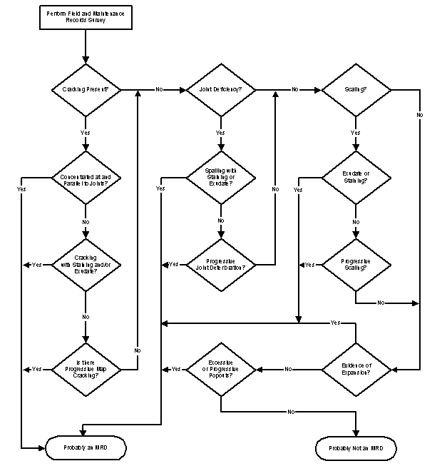
Before proceeding with coring and an extensive laboratory evaluation, it is important to make a preliminary assessment of whether the observed pavement deterioration is the likely result of an MRD. The proposed assessment is based primarily on the results of the distress survey, in which pavement distress data was collected in accordance with the procedure described above. Figure I-14 presents the flow chart illustrating the assessment procedure. The various aspects of the flow chart are discussed below.
Alternative Text for Figure I-14
Figure I-14. Flow chart for assessing likelihood of MRD.
In accordance with the modified LTPP procedures described previously, distresses affecting concrete pavements can be classified into four general categories: cracking, joint deficiencies (jointed concrete pavements only), surface defects, and miscellaneous distress. Figure I-14 uses these distress categorizations to systematically progress through the assessment process. The first question posed is whether cracking is present. If it is, the next question is whether the cracking is concentrated at and parallel to the joints/cracks as drawn on figure I-10 and listed in figure I-11 (note this pattern is characteristic of D-cracking as described in the LTPP manual). If so, it is possible that an MRD is affecting the pavement and a coring/laboratory analysis should be conducted to determine the specific mechanism(s).
If the cracking is not concentrated at joints/cracks, but does have surface staining and/or exudate associated with it, it is possible that an MRD is at work. This information can be garnered from figure I-11. In this case, coring should be conducted to more fully assess the distress mechanism.
Of the joint deficiencies presented in the modified LTPP procedure, the one of greatest interest in assessing a pavement for MRD is spalling, particularly if staining and/or exudate is associated with it. Refer to figures I-9 and I-11 to determine if this is the case. If so, it is possible that an MRD is responsible for the observed distress and coring should be conducted.
The primary LTPP surface defect of interest is map cracking. If the map cracking is associated with staining and/or exudate, has become progressively more extensive and/or severe over time, and/or is associated with signs of pavement expansion, it is possible that an MRD is at work and a coring/laboratory evaluation is warranted. Scaling is another surface defect commonly associated with MRD.If an exudate is associated with observed scaling and/or the scaling has become progressively more pronounced over time, it is also possible that an MRD is responsible. Excessive popouts are also an indicator of an MRD.
In general, if it is concluded that an MRD is possible, a coring/laboratory investigation should be conducted. In some cases, the type, extent, and severity of distress might be such that engineering judgment should be exercised to determine whether the project should be more thoroughly analyzed at this juncture using coring/laboratory evaluation, or whether a “wait and see” approach is more appropriate. If the latter alternative is selected, the pavement should be visually monitored on a routine basis to assess whether distresses potentially associated with MRD are becoming progressively worse, at which point coring/laboratory evaluation should be conducted.
This section of the guideline presents recommended practices for obtaining and handling samples of existing PCC pavements for the purpose of diagnosing MRD. It describes a systematic approach to determine the numbers of samples required and appropriate locations from which to retrieve those samples. It also presents techniques for retrieving, handling and storing the specimens in a manner that both maintains the physical integrity and chemical composition of the material.
This section describes the procedures for conducting field sampling and testing of pavements that appear to be currently exhibiting MRD. Included in this discussion are preparation activities, sampling and handling procedures, shipping procedures, and quality control activities. The sampling procedures discussed are only for the positive identification of MRD, and are not designed for checking construction quality control. In all cases, the samples must be obtained in a manner that reflects the variation pattern in the concrete. In hardened concrete being analyzed for MRD, this could require taking random samples from within a panel to determine the variability of the development of MRD within the panel. Alternatively, sampling could be concentrated in areas of known or suspected MRD development in order to characterize the conditions that have led to that development. Thus, the recommended sampling plan presented in this section can be altered to reflect unique field conditions as long as a minimum number of specimens is obtained to allow for accurate characterization.
Preparation for Field Sampling and Testing
Organization, Supervision, and Coordination
The first essential activity in field sampling and testing is the establishment and continuation of communication between all involved parties with regard to such items as planning, scheduling, responsibilities, and safety. A planning meeting should be held to initiate this communication and coordination well in advance of any field operations. It should be attended by members of the local MRD research team [including laboratory test technicians and representatives of any disciplines directly related to the materials being tested (e.g., geologists, petrographers, cement and concrete engineers, soil scientists, and so on)]. Additionally, if in-house personnel are not performing sampling, representatives of the sampling contractor should also be present. Names, addresses, and phone numbers of appropriate personnel should be exchanged. The scope of work, general locations of the pavement test sections, schedules, duties and responsibilities of supervisory personnel, permits (if any), reports and field documentation, safety regulations and requirements, legal requirements, emergency actions, and other concerns should be discussed and resolved at this time (SHRP 1990).
Other information that should be provided to the sampling contractor or personnel includes:
Coordination requirements for traffic control, permits, insurance, and other legal requirements related to fieldwork vary between governing agencies. Field-testing and sampling contractors should note that adequate advance notice will be required by highway agencies for traffic control arrangements; traffic control and lane closures may have to be provided by the contractor in some cases (SHRP 1990).
Permits and Insurance
All pavement sampling work should be performed within the right-of-way owned by the governing highway agency. If drilling or sampling contractors are used, it should be their responsibility to familiarize themselves with all applicable regulations and secure all necessary permits to perform the work, including interstate shipping of samples and transportation of nuclear gauges, if appropriate. Drilling and sampling contractors, if used, should exercise caution to avoid underground or overhead utilities in the performance of their work, and they should be made responsible for all injury to persons, damage to property, either directly or indirectly, that may result from their operations. The governing highway agency should provide any drilling or sampling contractors with available information on underground utilities from their records (SHRP 1990).
Vehicles, Equipment, and Materials
The field sampling and testing contractor should, at all times, provide at the field site all vehicles, equipment, and materials required by the contract. On sites that require test pits, a pavement saw capable of cutting the full depth of inseparable bound pavement layers should be used. These items should be in proper working order and meet Federal, State and/or local regulations (as appropriate) with respect to configurations, load restrictions, and safety requirements. Drivers of the vehicles must meet State and local requirements with respect to the number of hours driven/worked within a 7-day period. Expendable items, such as bits, packaging materials, rope, etc., shall be available in quantities that will preclude any operational delays. Nonconformance should be considered cause for shut down of operations without compensation of any kind (SHRP 1990).
Traffic Control and Safety
Whenever drilling, sampling, and testing activities are being performed on highway pavements, the safety of the operating crews as well as the traveling public is of the utmost importance. A comprehensive safety plan must be developed and implemented throughout the drilling, sampling, and testing contract. The safety plan should conform to local and Manual on Uniform Traffic Control Devices (MUTCD) requirements with regard to reflectorized vests, hard hats, safety glasses, adequate clothing (including foot gear), and first aid equipment. Standard operating procedures for drilling, sampling, and testing should be prepared and field crews should be trained using these procedures.
All traffic control arrangements should be scheduled as far in advance as possible and should adhere to the guidelines provided in the MUTCD or the agency’s governing requirements. Where traffic control activities are provided by the governing highway agency, any contractor field crews must be made aware of local safety requirements. When traffic control is provided by the contractor, procedures should be as required by the local governing highway agency. Work should be stopped and corrective actions taken when the crew chief or a designated highway agency official has any concerns about the safety of operations (SHRP 1990).
Visitors to the site should not be permitted within 8 m of drilling equipment. Vehicles in the work site should be facing in the direction of traffic to avoid any possibility of confusion. When a drill rig is facing the oncoming traffic, another vehicle should be located between the drill rig and the oncoming traffic and facing in the direction of traffic. Care should be exercised to minimize the encroachment of water from drilling operations onto the pavement surfaces open to traffic. In case of freezing conditions, deicing chemicals must be used to prevent the formation of ice on the traveled pavements and around the drilling operations (SHRP 1990).
Obtaining Hardened Concrete from In situ Pavements for MRD Investigations
ASTM C 42, Standard Test Method for Obtaining and Testing Drilled Cores and Sawed Beams of Concrete, governs the retrieval of cores or the sawing of beams from hardened concrete. However, it does not mention how to decide at what point or points such specimens be secured. ASTM C 823, Standard Practice for Examination and Sampling of Hardened Concrete in Construction, describes this, as well as many other aspects of sampling hardened concrete, in considerable detail. Other sources of information include Abdun-Nur (1970) and ACI 214, Evaluation of Results of Tests Used to Determine the Strength of Concrete. Standardization of this sampling process is difficult because it involves a great deal of judgment that is often difficult to standardize.
If the purpose of sampling hardened concrete is to assess overall properties and variability, it should be done randomly and objectively so that the samples taken are not weighted with unusually poor or unusually sound concrete. However, sampling in the course of investigations of MRD is different from quality control/assurance testing in that samples are commonly taken to exemplify unusual or extreme conditions or features that will aid in the identification of the causes of distress or failure of the concrete. It is this type of sampling that will be discussed below.
Sampling Plan (Number, Size, and Location of Samples)
The sampling plan must be developed with consideration of the results of field condition surveys that have been performed previously, which indicate whether or not the concrete is believed to be in similar condition and of similar quality. For the purposes of MRD testing, required sample numbers and sampling locations depend greatly upon the purpose of the study. In the vast majority of cases, evidence of distress will be obtained from the results of the visual assessment conducted in accordance with these guidelines. As such, targeted sampling is the appropriate approach for conducting an MRD evaluation used solely to characterize the type, severity, and extent of distress.
Selection of Coring S labs: Data collected during the field survey will be useful in selecting coring locations. For example, information detailing the location and characteristics of the project should be reviewed by the person(s) developing the sampling plan as well as by the person(s) that will be executing the sampling plan prior to their visit to the field site. This information should include a detailed sketch or drawing of typical observed MRD (figure I-10), including the crack pattern and the presence of staining and any exudate. It will also include categorization of the MRD distress (figure I-11) in terms of its cracking pattern (i.e., location, extent, and size), staining (i.e., location and color), exudation (i.e., presence, color, and extent), scaling (i.e., location, area, and depth), and surface texture (i.e., visible trails, discoloration, distressed).
The first step in determining the number of coring slabs for a given section is to use the results of the visual survey to assess the overall continuity of MRD within the project length. If the distress is uniformly distributed over the entire section length, one or two coring slabs may be sufficient to accurately characterize the type and severity of MRD. If the severity of the observed distress varies along the section length, at least one coring slab must be selected for each observed condition level.
Coring slabs should always occur within the inspection site(s) evaluated during the visual assessment. In this way, the detailed crack maps produced during the visual survey can be used to select specific coring slabs. It is recommended that a minimum of one slab be cored within each site. A minimum of four cores will be obtained from each slab (depending upon the observed distress). Specific details concerning recommended core locations are presented in the next section.
Number of Samples Per Coring Slab: The number of concrete samples and the dimensions of the pieces retrieved in the sampling operation should conform with the stipulations of the tests to which the samples will be subjected. In some instances, two or more tests may be performed on a single sample, provided that the first test does not modify the properties of the concrete to be evaluated by subsequent tests, as described in Guideline II in this series of guidelines. One example of acceptable successive testing is the determination of air-void content by linear traverse or modified point count followed by petrographic examination. An unacceptable sequence would be to stain a specimen using uranyl acetate and then analyze it using the scanning electron microscope (SEM).
An adequate number of cores must be taken to represent the condition of the pavement, yet the number must be restricted due to practical restraints on resources, both for field coring and laboratory analysis. Figures I-15 and I-16 are the proposed sampling rate developed in consideration of the unique nature of targeted sampling used in an MRD investigation of JCP and CRCP, respectively. As can be seen, the minimum number of cores required per slab is somewhat dependent on the type(s) of distress observed.
Recommended core locations are presented in figures I-17 through I-20. If the distress in a JCP is concentrated at the joints, a minimum of four core samples is required if the pavement is doweled. This is illustrated in figure I-17, where Cores A and B are positioned directly over the joint, with the center of the 150-mm core barrel offset 50 mm from the middle of the joint. In this way, the core can be cut in the direction of traffic to analyze the concrete a distance of 125 mm from the joint interface. Core A is obtained directly over a dowel bar located between the wheel paths to assess the corrosion of embedded steel. Core B is obtained between dowel bars in an area affected by MRD. Core C is the third core obtained near the joint, located approximately 0.3 m from both the joint and outside lane stripe. This core will be used to assess the extent of deterioration away from the joint, and thus may or may not be in an area visibly affected by MRD. Core D is positioned in a center slab location free of observable distress to determine if distress is present in the microstructure even though it is not yet visible on the surface.
Figure I-18 shows the recommended coring locations for a JCP suffering from MRD that is not concentrated at the joints. Cores A through D are basically the same as previously described and an additional core, Core E, has been added. This core will be obtained over visible deterioration to assist in identifying its cause. This deterioration may be a crack (as is common in map cracking), spall, or delamination. In some cases, this core may be pulled from deteriorated vibrator trails. It is noted that Core D should be taken from a visually non-distressed area. In some severe cases of MRD, a non-distressed area might not be available, in which case the core can be taken from a deteriorated area or not at all.
Figures I-19 and I-20 present a similar pattern for CRCP. It is noted that instead of obtaining Core A through a dowel bar, it instead should be taken through the reinforcing steel. All other cores should be obtained between the steel, if possible, unless corrosion of embedded steel is the specific distress being investigated.
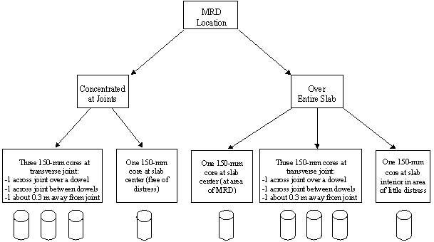
Figure I-15. Illustration of minimum number of cores for JCP required for MRD evaluation.
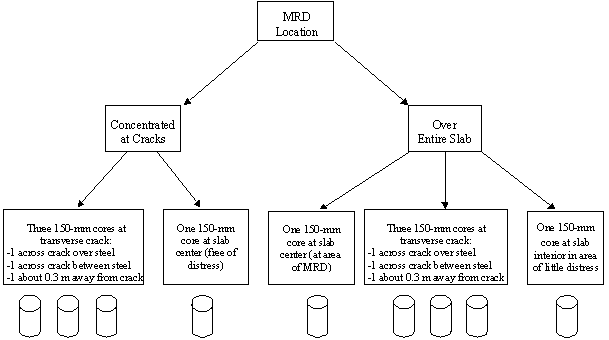
Figure I-16. Illustration of minimum number of cores for CRCP required for MRD evaluation.
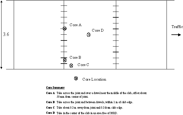
Figure I-17. Specific core locations for JCP with MRD concentrated at the joints.
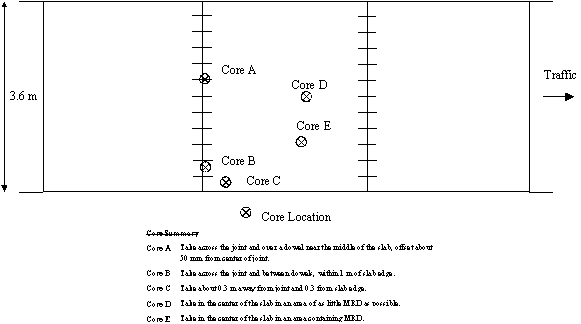
Figure I-18. Specific core locations for JCP with MRD not concentrated at joints.
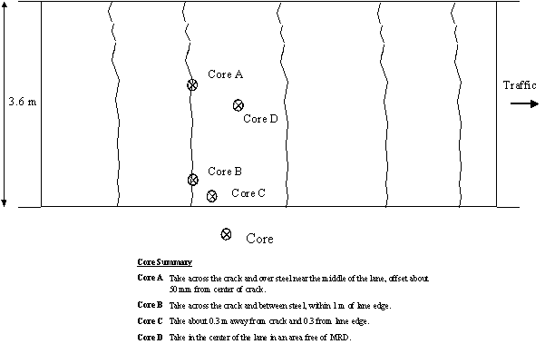
Figure I-19. Specific core locations for CRCP with MRD concentrated at the cracks.
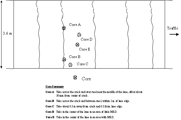
Figure I-20. Specific core locations for CRCP with MRD not concentrated at cracks.
It is noted that these recommendations present the minimum number of cores needed for the evaluation. In some instances, additional cores would be useful, particularly if certain unusual features were observed. Field crews should be instructed to take additional samples if unusual features are observed, carefully noting the location and the feature of interest.
Physical Requirements for Samples: All core samples taken should include the full thickness of the concrete because the development of cracking, deterioration of the cement paste, progress of cement–aggregate reactions, and other features may vary significantly with depth. The diameter of core specimens for MRD identification is not critical as long as it is sufficient to provide a representative section of the concrete structure once it is prepared for examination. In general, the use of 150-mm-diameter cores is preferable, although 100-mm-diameter cores may suffice. Cores that are intended for use in petrographic examination must be unaltered cores that have not been subjected to strength testing or other destructive processes.
Specimen Retrieval
Pavement surfaces should be marked at the coring location to indicate the direction of traffic before coring or sawing. The markings should be clearly visible and easily interpreted after the coring operation is complete.
Procedures that cause mechanical or thermal damage to cores should not be used in the retrieval of cores or beams intended for shipment to the laboratory.
Samples to be retained for laboratory testing must be protected from contamination, damage, and other processes that might change the character of the material being examined or tested. Possible sources of contamination include other layers at the same site as well as materials carried by coring rigs and other equipment from other sites. It is desirable that the surface of all cores or beams be rinsed with fresh water to remove coring or cutting slurry prior to wrapping or packing for transport and/or shipping.
Information concerning the location, manner of retrieval, and field condition of all hardened concrete samples should be recorded for future reference. A typical hardened concrete sampling log sheet that may be useful for a coring site is presented in figure I-21.
Labels that clearly identify the core (including the coring site, slab number, core location, and date of coring) should be prepared and affixed to each sample. An example identification label is shown in figure I-22.
Air-Void Samples: Whenever it is suspected that the entrained air system of hardened PCC is not sufficient to provide protection from freezing and thawing deterioration, or whenever it is suspected that the cause of low strength might be excess air content, air-void system measurements may be required. If the air-void system of the entire concrete placement is suspect, sampling should be performed in accordance with the instructions detailed in ASTM C 457:
|
LABORATORY LOG OF PCC PAVEMENT CORES Sheet ____ of ____ Project Designation: State: Highway: Nearby City and Distance: Direction: No. of Through Lanes (in direction sampled): Lane Sampled: Beginning Milepost/Station: End Milepost/Station: Operator: Core Diameter: Coring Date: Core Barrel Tip Type: Job ID: Note: Each column shown below should be used to record information for all cores/pieces extracted from a single panel. “Depth” should be measured from the pavement surface to the bottom of the core/piece and recorded to the nearest 2 mm. Front direction is the direction of traffic.
|
Figure I-21. Typical hardened concrete sampling log sheet.
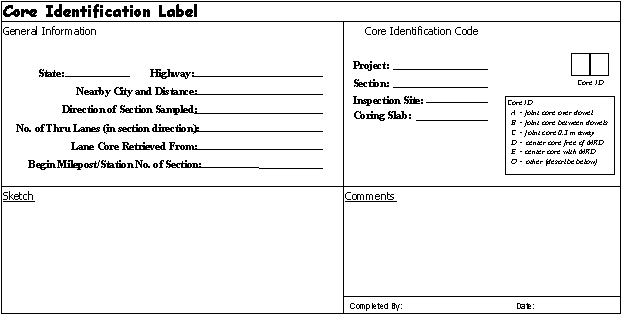
Figure I-22. Example core identification label.
To determine the compliance of hardened concrete with requirements of specifications on the air-void content or specific surface and spacing factor of the void system, a sample of the concrete should be obtained from at least three locations in the body of concrete and microscopical measurements should be made on at least one section prepared from each of at least three of such samples.
The three locations within the entire body of the placement under study from which samples must be obtained should be determined in accordance with a rigorously developed random sampling plan, without regard for areas of extreme deterioration. Areas exhibiting specific features of interest should be sampled separately. Each sample should be large enough to allow the petrographer to prepare at least the minimum area of finished surface given in ASTM C 457, table 1.
Frozen Concrete: If it is suspected that the subject concrete was frozen before gaining adequate strength to resist freezing damage, at least one specimen should be obtained from the edge of the placement, from up against the form, or from a place exposed to the ambient temperature. It is in such an exposed area that the casts of ice crystals will form first. If companion cylinders were cast and cured similarly to the placement, they may show ice crystal casts on the surface in contact with the mold. Exposure of fresh concrete to ambient freezing temperatures usually affects the wearing surface only if the curing material is insufficient to retain the heat generated by the hydration of the cement or if the curing material is prematurely removed (possibly by wind).
Established sampling plans, methods, and procedures are often not enough to ensure adequately intact samples reaching the laboratory for the preparation of specimens for testing. Proper handling and care of samples in the field and in storage and shipping are essential if test results obtained from specimens prepared from these samples are to be meaningful and if reliable conclusions are to be drawn from such results.
Generally accepted field handling procedures include:
There are generally no limits on the duration of storage for hardened concrete specimens, provided that the desired storage conditions (if any) are maintained with respect to specimen moisture and temperature, exposure to atmospheric conditions, and so on. These conditions should be established such that the condition and composition of the specimen represent, as closely as possible, the condition of the field concrete at the moment of retrieval.
Shipping of SamplesIn general, samples must be adequately identified and shipped in clean, strong containers. If the moisture content of the sample is important, the container must be moisture-tight. Containers should always be clean and free of any potential contaminants.Shipping containers should be labeled with suitable rot- and mildew-resistant identification tags containing all of the information deemed pertinent so that field reporting, laboratory logging, and test reporting may be facilitated. Duplicate labels should be placed inside of the containers. If the containers have removable tops, the labels should be attached to the body of the container to avoid possible mislabeling of a sample if the container lids are accidentally switched.Care should be taken to prevent damage to concrete specimens during transport and shipping. Intact cores or large core fragments can generally be transported from the field and shipped over short distances without damage when wrapped in plastic bubble wrap packing material and placed in appropriately sized plastic cylinder molds with lids. Similarly, sawed beams can also be wrapped in plastic bubble wrap packing material and shipping tape and placed in protective tubs or containers for transport from the field and shipping over short distances.Specimens that will be shipped by common carrier should be afforded additional protection from damage. While there is no absolute way to prevent damage during shipping by common carrier, the following techniques and considerations may be helpful:
The distress survey, which provides a systematic procedure for conducting distress surveys of pavements exhibiting MRD, not only establish the overall condition of the pavement, but also a means to characterize the manifestations of MRD occurring on the pavement surface. Table I-2 summarizes the important parts of the distress surveys. After the conduct of the distress survey, the next step is to determine whether coring is warranted and, if it is, to identify testing locations and the actual material sampling for later testing in the laboratory. This guideline then presents procedures for obtaining and handling hardened concrete samples for use in identifying the presence of MRD in PCC pavements. It describes a systematic approach to determining the numbers of samples required and appropriate locations from which to retrieve those samples, as well as techniques for retrieving, handling, and storing the specimens in a manner that maintains the physical integrity and chemical composition of the material. Compliance with the proposed guideline will help to ensure that subsequent laboratory tests and analyses provide accurate and meaningful indications of MRD presence or potential.