U.S. Department of Transportation
Federal Highway Administration
1200 New Jersey Avenue, SE
Washington, DC 20590
202-366-4000
Federal Highway Administration Research and Technology
Coordinating, Developing, and Delivering Highway Transportation Innovations
 |
| This report is an archived publication and may contain dated technical, contact, and link information |
|
Publication Number: FHWA-RD-01-164 Date: March 2002 |
This chapter presents the second of the three guidelines prepared as part of FHWA Project No. DTFH61-96-C-00073 entitled Detection, Analysis, and Treatment of Materials-Related Distress in Concrete Pavements. This guideline is divided into two major sections. The first section addresses the laboratory procedures used to examine concrete specimens and presents a systematic method of data collection, recording, and reporting. The second section of this guideline presents a systematic approach for interpreting the laboratory data, along with design, construction, field evaluation, and performance data, to make a diagnosis as to what distress mechanism(s) may be present.
A key step in identifying the cause of a materials-related distress (MRD) is laboratory analysis of the distressed concrete. The laboratory analysis of concrete is facilitated by the systematic application of test methods specifically designed to identify MRD by searching for known symptomatic indicators, or diagnostic features. However, laboratory results are susceptible to broad interpretation and a rigid adherence to laboratory protocol, along with the judgment of an experienced petrographer, analyst, or engineer is often required to avoid incorrectly diagnosing a problem.This section of the guideline is designed to be an informational guide for technical personnel and presents laboratory methods available for identifying MRD in concrete pavements using petrography, SEM, and other techniques. It also provides a brief description of commonly applied procedures and a suggested format for gathering and storing data. This manual is intended for both engineers and analysts where an engineer is defined as the person presenting the problem to the laboratory and the analyst is the laboratory personnel charged with diagnosing the concrete problem. In many cases, this may be the same person but often, they are members of a team of people that need to communicate clearly to arrive at a cause, or causes, for the suspected MRD. In this sense, both engineers and analysts must have a clear understanding of the required tests and the possible caveats associated with each test to properly interpret the results.This section is organized starting with a brief description of recommended literature that will provide background information. This is followed by an overview of the approach to laboratory testing and a recommended data collection protocol using standard data collection forms. Last, an approach for data analysis and interpretation is presented. More detailed descriptions of the equipment and methods used to conduct optical microscopy, scanning electron microscopy (SEM), x-ray diffraction (XRD), and chem-laboratory analysis are presented in appendix B.
A number of valuable reference materials exist that provide an excellent presentation of the current body of knowledge related to methods of performing or interpreting diagnostic tests on concrete. Below are brief descriptions of a small selection of publications that provide an excellent review of various aspects of concrete petrography. Each publication covers a different aspect of forensic concrete analysis applicable to MRD identification and it is recommended that anyone charged with the analysis of concrete become familiar with these publications. This is not intended to be a complete list of all available publications discussing concrete analysis or diagnosis of deterioration. Instead, it is a list of publications that provide the average analyst with the required information to become proficient at analyzing concrete.
Rock and Mineral Identification for Engineers (FHWA 1991) is an excellent resource for rock and mineral identification. The purpose of this handbook is to summarize the distinctions between different types of rocks commonly used as aggregates and aid in their identification by engineers in the field or laboratory. Easily performed simple tests not requiring special facilities are introduced. The key information provided in the manual is summarized in a laminated pocket sized flowchart that is easily carried in the field. This publication is an excellent summary of fundamental petrology and can serve as a good primer for non-geologists who need to identify different rock types. Also, the role of aggregates in various types of MRD is briefly discussed.
An excellent manual on petrographic methods is entitled, Petrographic Methods of Examining Hardened Concrete: A Petrographic Manual (Walker 1992). This manual provides a detailed summary of the fundamental methods of concrete analysis including chapters on equipment and materials, sample documentation, preparation of specimens, and the observation of cracks, voids, and paste using the stereo and petrographic optical microscopes. In addition, other concrete constituents and parameters are discussed including mineral admixtures and water-to-cement (w/c) determination. Alkali–aggregate reactivity (AAR) is discussed and numerous photographs and micrographs are included to illustrate the different types of distresses. Various types of optical microscope methods are presented including a section on fluorescence microscopy techniques. Numerous color pictures of various concrete specimens are included and overall, detailed steps on the fundamental tests for concrete analysis are presented. It is recommended that anyone new to the concrete sample preparation and microscopy methods obtain a copy of this manual for reference purposes.
Another useful concrete petrography publication is Concrete Microscopy (Roy et al. 1993a). It provides a detailed description of the fluorescence microscopy method, including numerous micrographs showing various features as seen in fluorescence microscopy and the effects of poor sample preparation. Detailed instructions on the method of gathering and the interpretation of data are included.
A third valuable publication on the subject of concrete petrography is Concrete Petrography by St John et al. (1998). This excellent textbook discusses concrete petrographic techniques, providing information and references along with details of specific techniques. The text also discusses defects in, and deterioration of, concrete and provides a wide range of micrographs illustrating common microstructural features. Also, details of optical and chemical properties of phases found in concrete are presented.Significance of Tests and Properties of Concrete and Concrete-Making Materials [American Society for Testing and Materials (ASTM) 1994] covers a broad range of concrete topics, addressing virtually all tests of concrete and mechanisms of concrete distress and deterioration. The compilation is laid out in six general sections; General Information, Freshly Mixed Concrete, Hardened Concrete, Concrete Aggregates, Other Concrete Making Materials, and Specialized Concretes. A well-known expert provides a very detailed and complete discussion of the issues under each section. Each chapter has extensive references allowing for more detailed examination of any aspect presented. It is an excellent reference book and a recommended addition to the laboratory library.
There are a large number of ASTM standards that address laboratory practices relative to concrete. In general, three of these standards directly address the examination of hardened concrete and should serve as a basis for any laboratory examination of concrete exhibiting MRD. The applicable standards are ASTM C 457 Test Method for Microscopical Determination of Parameters of the Air-Void System in Hardened Concrete, ASTM C 823 Practice for Examination and Sampling of Hardened Concrete in Constructions, and ASTM C 856 Practice for Petrographic Examination of Hardened Concrete. One important impact of these standards is in the case of litigation where the credibility of laboratory results will be based in part on adherence to these accepted standards. Unfortunately, as detailed procedures, these ASTM standards often fall short, forcing the engineer to make decisions about methods without sufficient background information.
When MRD is suspected of playing a role in the premature deterioration of concrete, laboratory tests are essential to help understand the underlying mechanisms at work. In reviewing the various types of MRD, it is clear that the distress mechanisms involve physical and/or chemical processes that occur between the concrete and its environment. These processes ultimately lead to changes in the concrete microstructure, which may in turn affect the durability of the concrete. The relationship between material characteristics and microstructure is not unique to concrete. The study of material microstructure forms the basis of materials science and engineering. In the same vein, the typical laboratory methods used to characterize concrete’s microstructure are the same as those used to characterize the microstructure of other materials. These methods include optical microscopy (OM), SEM, analytical chemistry, and XRD.
Optical microscopy using the stereo microscope and the petrographic microscope are the most versatile and widely applied tools for diagnosing causes of MRD. Electron microscopy is becoming more prevalent, especially for chemical identification of reaction products and other secondary phases using energy dispersive spectroscopy (EDS). Analytical chemistry plays a very important role in determining key parameters of the concrete (e.g., w/c, chloride content). XRD is applied in some cases but is not widely used in the analysis of concrete.
Often, when diagnosing concrete distress, there is no clear answer as to which single distress mechanism caused the failure. This has been referred to as "the straw that broke the camel's back" theory (Erlin 1993) where multiple distress mechanisms are active and it is the combination of these, in concert, that lead to the failure of the concrete. Various types of distress mechanisms can occur simultaneously in concrete and each can incrementally contribute to the ultimate failure of the material. Although many cases of concrete distress are difficult to attribute to only one mechanism, a majority of MRD cases are easily diagnosed. This is often accomplished by use of the optical microscope alone. As a result, most laboratory diagnostic procedures have focused heavily on the use of optical microscopic methods. Analytical chemistry methods have also been used, such as staining techniques and determination of parameters such as w/c. Other techniques, such as SEM and XRD, have also been widely used by researchers and are becoming more common for forensic investigations of concrete failures.
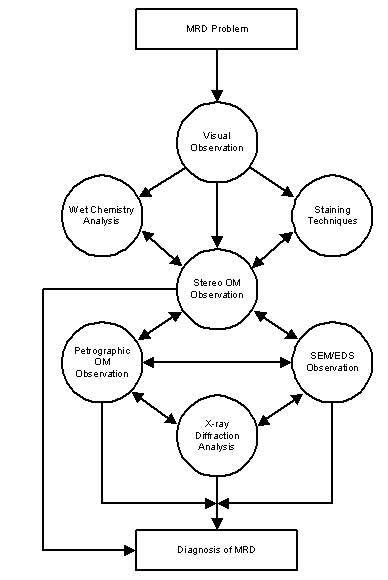
When initiating the study of deteriorated concrete, or any material, an analysis plan of how to approach the problem must be followed. This plan very often reflects a process of elimination; rather than proving what the MRD is, prove instead what it is not. In this way, diagnosis of the MRD responsible is achieved. The basic flow of a typical laboratory analysis is presented in figure II-1. The general approach is to start very broadly, inspecting the concrete by eye. As the concrete is examined the analyst should look for diagnostic features, which are essentially conditions or physical properties of the concrete that will assist in diagnosis. After evaluating or assessing the core visually, a hand lens or stereo microscope can be used to look more closely at pertinent features. In some cases, as a result of this visual and stereo microscope analysis, the probable or certain cause of distress is identified. In most cases, a few potential MRD types can be eliminated and further analysis can then focus on those remaining. At this point, the analyst must decide which examination technique can be performed to confirm a given MRD, or eliminate other MRD types, thereby narrowing the choices to the most probable mechanism.
The process is as follows. A sample of concrete exhibiting distress comes into the lab and is first visually inspected. After specimens are produced from a core sample, it is common to use the stereo OM for initial optical analysis and staining techniques to help identify ASR or sulfate phases. Next, the specimen can be viewed in the petrographic microscope and/or SEM. This process of using the stereo OM, petrographic OM, and SEM is iterative and it is quite common to view the same specimen in all three instruments. Staining in particular can assist in the optical evaluation although it may interfere with SEM analysis.
As of this writing, a SEM is not available in most State highway agency (SHA) laboratories. However, laboratories trying to actively diagnose and treat MRD in concrete should consider either the purchase of an SEM or establishing cooperative arrangements with other institutions to gain access to an SEM. Although a trained petrographer can use the petrographic microscope and identify practically all minerals and aggregate reaction products present in a concrete specimen, this often requires thin section preparation or detailed analysis of picked grains with refractive index liquids. This requires a highly skilled concrete petrographer to analyze and interpret the complex and vast array of information revealed by the petrographic OM. In contrast, the SEM is an instrument any laboratory technician can learn to operate. Another advantage of the SEM is the simple presentation of the results in a form engineers, technologists, and scientists can all understand.
Figure II-1. Fundamental process for analyzing a concrete MRD sample.
Both x-ray mapping and x-ray microanalysis are very useful ways of identifying components of the microstructure. However, the use of the SEM has some disadvantages. Cracking problems in the conventional SEM (CSEM), microanalysis problems in the environmental SEM (ESEM), and a much higher initial cost with a significant ongoing maintenance cost are associated with its operation.
When analyzing a concrete specimen, the concrete should be viewed as an entity consisting of a system of four principal components: air, hydrated cement paste, coarse aggregate, and fine aggregate. All available methods to examine the system and its components should be used, looking for all features that will help in the diagnosis. The ability to establish certain features as being normal greatly helps in deducing the cause of the problem. For example, no apparent coarse aggregate cracking all but eliminates aggregate freeze-thaw deterioration as a cause. As another example, the presence of an adequate, uncompromised air-void system helps rule out paste freeze-thaw damage as the primary distress mechanism. Systematic examination of all components of the concrete is crucial to determining the cause of failure.
In general, it is recommended that tests be carried out in the order presented in figure II-1. However, if properly done, deviations from this approach should still lead to the same result. That is to say no one test depends directly upon the outcome of another. In practice, some tests must be performed prior to others. One example is the Strategic Highway Research Program (SHRP) uranyl acetate test, which contaminates the concrete with uranium. When using an SEM equipped with an EDS for microanalysis of stained aggregate reaction products, the uranium M-series x-ray lines obliterate the potassium K-series x-ray lines, making identification of potassium in the aggregate reaction product impossible. Therefore, qualitative EDS microanalysis of ASR reaction products must be performed on unstained concrete. As another example, concrete specimens analyzed in a CSEM are subjected to a high vacuum, and thus microcracking due to desiccation of the paste will occur. It is therefore best to first observe such specimens optically prior to CSEM evaluation to assess paste microcracking.
In the end, the proper examination of concrete requires the application of independent, unbiased testing methods in a uniform and controlled approach. The number of required tests is determined by the complexity of the MRD while the implementation may depend upon various factors including scheduling of laboratory equipment and personnel.
The purpose of this section is to provide an overview of the analytical procedure used to examine MRD in concrete. To accomplish this standard analysis, data sheet templates designed to follow a sample (most commonly a core) through the laboratory evaluation are provided. The use of these data sheets will facilitate laboratory analyses and data interpretation in a number of ways. First, these data sheets provide a framework for the “questions you ask about the material” and are intended to be consistent with the requirements of ASTM C- 856 Practice for Petrographic Examination of Hardened Concrete. It is noted that the individual questions and data queried in these forms do not constitute the full implementation of ASTM C- 856. Instead they focus on the analysis of deteriorated pavement concrete, which is only a small fraction of what this very broadly applied Practice addresses.Another benefit of using data forms is that they serve as the “lab notebook” for recording and archiving laboratory results. As an example, careful inspection with a stereo microscope alone can often reveal the reason for concrete failure. Although a diagnosis of MRD based on stereo microscope observations may be correct, it is often necessary to use other techniques to get confirmation. The data sheets provide a systematic way of gathering and archiving the results of multiple laboratory analyses that may be conducted by multiple technicians, often in different laboratories. Finally, personnel outside the laboratory want to know that a core was examined for all possibilities and no rush to judgment was made on limited data. By using standard data collection forms, the diagnostic indicators laboratory personnel were looking for will be clear to others. When tests are not performed, it should be noted on the data sheet along with an explanation of why the test was not conducted. This reporting protocol will help provide an understanding of the decisions made by laboratory personnel to arrive at a diagnosis of material failure. The data sheets provided are separated into the following major categories roughly corresponding to the steps illustrated in figure II-1:
|
|
|
Within each data sheet, tests and diagnostic features are presented in a tabular format along with possible or common results. It is up to the analyst to observe and make judgments about the concrete relative to the questions posed on each data sheet. Laboratory personnel should complete only those data sheets that apply to analyses conducted. These observations are combined with all other data to arrive at a diagnosis of the MRD observed.
Analysts are expected to enter data and observations on these forms and a copy of these forms accompanies each core, following it through the analysis process. Additionally, completed forms should be provided to the engineer along with the final laboratory report. Copies of these forms are provided in appendix C. The groupings and individual forms are as follows:
Group 1: Core Receipt and Cataloging
Group 3: Stereo Optical Microscope Examination.
Group 5: Petrographic Optical Microscope Examination
Group 6: Scanning Electron Microscope Examination
Group 8: X-ray Diffraction Analysis
|
LABORATORY LOG OF PCC PAVEMENT CORES Sheet ____ of ____ Project Designation: State: Highway: Nearby City and Distance: Direction: No. of Through Lanes (in direction sampled): Lane Sampled: Beginning Milepost/Station: End Milepost/Station: Operator: Core Diameter: Coring Date: Core Barrel Tip Type: Job ID: Note: Each column shown below should be used to record information for all cores/pieces extracted from a single panel. “Depth” should be measured from the pavement surface to the bottom of the core/piece and recorded to the nearest 2 mm. Front direction is the direction of traffic.
|
Figure II-2. Group 1: Laboratory log of PCC pavement cores.
|
Analyst |
Core taken by |
Date Cored |
||
|
Date |
Core ID |
Job ID |
||
|
CORE SAMPLED FOR LABORATORY ANALYSIS |
|
|---|---|
|
Location (circle one): A B C D E Other?: |
Picture: Top View |
|
Core Diameter: mm |
|
|
No. of Pieces: |
|
|
Ht. Piece #1: mm |
|
|
Wt. Piece #1: kg |
|
|
Ht. Piece #2: mm |
|
|
Wt. Piece #2: kg |
|
|
Ht. Piece #3: mm |
|
|
Wt. Piece #3: kg |
|
|
Ht. Piece #4: mm |
|
|
Wt. Piece #4: kg |
|
|
Total Ht.: mm |
|
|
Total Wt.: kg |
|
|
Sketch |
Picture: Side View |
Figure II-3. Group 1: Core sampled for laboratory analysis.
|
Analyst |
Job ID |
|
Date |
Core ID |
|
Visual Inspection - General Condition of Concrete |
|||
|
Diagnostic Feature |
Options |
Comments
|
|
|
Ring when struck lightly with a hammer? |
Yes |
No |
|
|
Does it break with your fingers? |
Yes |
No |
|
|
Is the concrete well consolidated? |
Yes |
No | |
|
Is segregation apparent? |
Yes |
No |
|
|
Orientation/parallelism of aggregates? |
Yes |
No |
|
|
Visible surface deposits or exudate? |
Yes |
No |
|
|
Are cracks apparent in the paste? |
Yes |
No |
|
|
Are the cracks widespread? |
Yes |
No |
|
|
Cracks through aggregates? |
Yes |
No |
|
|
Are there cracks around aggregates? |
Yes |
No |
|
|
Deposits in cracks? |
Yes |
No |
|
|
Embedded items present? |
Yes |
No |
|
|
Adequate cover over the embedded items? |
Yes |
No |
|
|
Are embedded items corroded? |
Yes |
No |
|
|
Underside voids on elongated aggregates? |
Yes |
No |
|
|
Are air voids filled? |
Yes |
No |
|
|
Does paste hardness seem normal? |
Yes |
No |
|
|
Is paste hardness uniform throughout? |
Yes |
No |
|
|
High paste content? |
Yes |
No |
|
|
Gradation of aggregates? |
gap |
uniform |
|
|
Coarse aggregate top size? |
|||
|
Coarse aggregate type? |
crushed |
natural |
|
|
Coarse aggregate rock type? |
|||
|
Fine aggregate type? |
crushed |
natural |
|
|
Fine aggregate rock type? |
|||
|
Alteration/reaction with aggregates? |
Yes |
No |
|
Comments_______________________________________________________________
_______________________________________________________________________
_______________________________________________________________________
_______________________________________________________________________
_______________________________________________________________________
_______________________________________________________________________
_______________________________________________________________________
Figure II-4. Group 2: General condition of the concrete.
| Analyst |
Job ID |
||
|
Date |
Sample ID |
||
|
Stereo OM - Observations of the Concrete Attach additional documentation and micrographs as needed. |
|||
|
Diagnostic Feature |
Options |
Comments |
|
|
Bleeding? |
bleed channels |
||
|
Fractures? |
none through aggregates |
||
|
Air void infilling? |
yes partial no |
||
|
Air void shape |
spherical irregular |
||
|
Embedded item condition? |
good corroded |
||
|
Surface condition? |
cracked carbonated |
||
|
Aggregate reaction products? |
yes no |
||
|
Location of reaction products? |
air voids |
||
|
Gaps around coarse or fine aggregates? |
description |
||
|
Gap widths larger for larger particles? |
yes no |
||
|
Are the gaps filled? |
yes no |
||
|
Coarse aggregate type? |
gravel quarried |
||
|
Lithological types of coarse aggregate? |
specify types identified |
||
|
Orientation/parallelism of coarse aggregate? |
specify which and specify direction of orientation |
||
|
Fine aggregate type? |
natural other (specify) |
||
|
Lithological types of fine aggregate? |
specify types identified |
||
|
Paste color – note uniformity of color. |
white light gray |
||
|
Paste hardness – note uniformity of hardness. |
soft hard |
||
Comments ______________________________________________________________
_______________________________________________________________________
Figure II-5. Group 3: Stereo OM - observations
of the concrete.
|
Analyst |
Job ID |
|
Date |
Sample ID |
|
Stereo OM Observations - Alterations of the Aggregates Attach additional documentation and micrographs as needed. |
||
|
Coarse Aggregates |
||
|
Diagnostic Feature |
Options |
Comments |
|
Degree of alteration? |
isolated extensive |
|
|
Cracking in aggregates? |
yes no |
|
|
Internal cracks narrow from center of aggregate out? |
yes no |
|
|
Cracks through aggregates extend into the paste? |
yes no |
|
|
Dissolution or softening of aggregates? |
yes no |
|
|
Reaction rims? |
yes no |
|
|
Reaction products from alteration? |
yes no |
|
|
Location of reaction products? |
air voids |
|
|
Fine Aggregates |
||
|
Diagnostic Feature |
Options |
Comments |
|
Degree of alteration? |
isolated extensive |
|
|
Cracking in aggregates? |
yes no |
|
|
Internal cracks narrow from center of aggregate out? |
yes no |
|
|
Cracks through aggregates extend into the paste? |
yes no |
|
|
Dissolution or softening of aggregates? |
yes no |
|
|
Reaction rims? |
yes no |
|
|
Reaction products from alteration? |
yes no |
|
|
Location of reaction products? |
air voids |
|
Narrative Description of Alteration _______________________________________________
_______________________________________________________________________
Figure II-6. Group 3: Stereo OM observations
- alterations of the aggregate.
|
Analyst |
Job ID |
|
Date |
Sample ID |
Results of ASTM C 457
|
Method Used: |
Length Traversed |
|
Area Traversed |
|
|
Magnification |
|
|
No. of Stops |
|
Air-Void System Parameters |
|||
|
Specification |
Typical Range for Acceptable Air Entrained Concrete |
Calculated Value for Original Air-Void System |
Calculated Value for |
|
Spacing Factor ( |
0.01 - 0.02 mm |
||
|
Specific Surface (a) |
23.6 - 43.3 mm-1 |
||
|
Paste/Air Ratio |
4 - 10 |
||
|
Void Frequency (n) |
|||
|
Phase Abundance Analysis |
|
|
Phase |
Volume Percent |
|
Coarse Aggregate |
|
|
Fine Aggregate |
|
|
Paste |
|
|
Original Air Content |
|
|
Filled Voids |
|
Comments______________________________________________________________
_______________________________________________________________________
_______________________________________________________________________
_______________________________________________________________________
_______________________________________________________________________
_______________________________________________________________________
_______________________________________________________________________
_______________________________________________________________________
Figure II-7. Group 3: Results of ASTM C
457.
|
Analyst |
Job ID |
|
Date |
|
Sulfate/ASR Reaction Product Staining |
|||
|
Core ID |
Method Used |
Positive Staining |
Comments |
|
Yes No |
|||
|
Yes No |
|||
|
Yes No |
|||
|
Yes No |
|||
|
Depth of Carbonation |
||
|
Core ID |
Depth of Carbonation |
Comments |
Comments_______________________________________________________________
_______________________________________________________________________
_______________________________________________________________________
_______________________________________________________________________
_______________________________________________________________________
_______________________________________________________________________
_______________________________________________________________________
Figure II-8. Group 4: Summary of staining
tests.
|
Analyst |
Job ID |
|
Date |
Sample ID |
|
Petrographic OM - Observations of the Concrete |
||
|
Diagnostic Feature |
Selected Descriptors |
Comments |
|
w/c in bulk? |
specify method and value |
|
|
w/c at surface if different than bulk? |
specify method and value |
|
|
Evidence of trapped bleed water? |
water voids below horizontal aggregate faces |
|
|
Air-void structure at surface intact? |
specify |
|
|
Calcium hydroxide depletion? |
specify |
|
|
Sub parallel cracking or delamination at surface? |
specify |
|
|
Paste density variations around the aggregates? |
specify |
|
|
Cracking? |
cracks through aggregates |
|
|
Secondary deposits? |
yes no |
|
|
Location of secondary deposits? |
air voids |
|
|
Identify deposits. |
specify |
|
|
Lithological details of coarse aggregate? |
specify |
|
|
Lithological details of fine aggregate? |
specify |
|
|
Mineral admixtures? |
present not present |
|
|
Identification |
fly ash silica fume |
|
Narrative Description of Petrography Results: _______________________________________
_______________________________________________________________________
_______________________________________________________________________
_______________________________________________________________________
_______________________________________________________________________
Figure II-9. Group 5: Petrographic OM -
observations of the concrete.
|
Analyst |
Job ID |
|
Date |
Sample ID |
|
Petrographic OM Observations - Alterations of the
Aggregates |
||
|
Coarse Aggregates |
||
|
Diagnostic Feature |
Selected Descriptors |
Comments |
|
Degree of alteration? |
isolated extensive |
|
|
Cracking in aggregates? |
yes no |
|
|
Internal cracks narrow from center of aggregate out? |
yes no |
|
|
Cracks through aggregates extend into the paste? |
yes no |
|
|
Dissolution of aggregate? |
yes no |
|
|
Reaction rims? |
yes no |
|
|
Reaction products? |
yes no |
|
|
Location of reaction products? |
air voids |
|
|
Identify reaction products |
specify |
|
|
Fine Aggregates |
||
|
Diagnostic Feature |
Selected Descriptors |
Comments |
|
Degree of alteration? |
isolated extensive |
|
|
Cracking in aggregates? |
yes no |
|
|
Internal cracks narrow from center of aggregate out? |
yes no |
|
|
Cracks through aggregates extend into the paste? |
yes no |
|
|
Dissolution of aggregate? |
yes no |
|
|
Reaction rims? |
yes no |
|
|
Reaction products? |
yes no |
|
|
Location of reaction products? |
air voids |
|
|
Identify reaction products |
specify |
|
Narrative Description of Alteration _______________________________________________
_______________________________________________________________________
_______________________________________________________________________
_______________________________________________________________________
Figure II-10. Group 5: Petrographic OM observations
- alterations of the aggregate.
|
Analyst |
Job ID |
|
Date |
|
SEM - General Conditions |
|
|
SEM or CSEM |
Operating Pressure |
|
Samples Conductive Coated (Y/N) |
Coating Method/Thickness |
|
Samples Dehydrated (Y/N) |
Dehydration Method |
|
SEM - Conditions for Quantitative Microanalysis |
|
|
SEM or CSEM |
Operating Pressure |
|
Accelerating Voltage |
Beam Current |
|
Working Distance |
Standardless or full-quantitative (with standards) analysis? |
|
Oxygen measured or determined by stoichiometry? |
Analysis done by EDS or WDS? |
|
SEM - Conditions for X-ray Mapping |
|
|
SEM or CSEM |
Operating Pressure |
|
Accelerating Voltage |
Beam Current |
|
Working Distance |
Map Resolution |
|
Map Dwell Time |
Elements Mapped |
Comments ______________________________________________________________
_______________________________________________________________________
_______________________________________________________________________
_______________________________________________________________________
_______________________________________________________________________
_______________________________________________________________________
_______________________________________________________________________
_______________________________________________________________________
_______________________________________________________________________
_______________________________________________________________________
Figure II-11. Group 6: SEM - general conditions.
|
Analyst |
Job ID |
|
Date |
Sample ID |
Summary of Scanning Electron Microscope Analysis
__________________________________________________________________________
__________________________________________________________________________
__________________________________________________________________________
__________________________________________________________________________
__________________________________________________________________________
__________________________________________________________________________
__________________________________________________________________________
__________________________________________________________________________
__________________________________________________________________________
__________________________________________________________________________
__________________________________________________________________________
__________________________________________________________________________
__________________________________________________________________________
__________________________________________________________________________
__________________________________________________________________________
__________________________________________________________________________
__________________________________________________________________________
__________________________________________________________________________
__________________________________________________________________________
__________________________________________________________________________
Figure II-12. Group 6: Summary of scanning
electron microscope tests.
|
Analyst |
Job ID |
|
Date |
Summary of Chemical Tests
|
Determination of w/c |
|||
|
Specimen ID |
Method Used |
Measured w/c |
Comments |
|
Determination of Sulfate Concentration |
|||
|
Specimen ID |
Method Used |
Sulfate Concentration |
Comments |
|
Determination of Chloride Concentration |
|||
|
Specimen ID |
Method Used |
Chloride Concentration |
Comments |
Figure II-13. Group 7: Summary of chemical tests.
|
Analyst |
Job ID |
|
Date |
|
XRD - Analytical Conditions |
|
|
Type of specimen (e.g., powder, slab) |
Specimen mounting method? (Side drifted, pressed pellet) |
|
X-ray tube kV and mA |
X-ray tube target material |
|
Was a primary beam filter used and what type? |
Monochromater used? (Y/N) |
|
Divergence slit (specify mm or degrees) |
Receiving slit (specify mm or degrees) |
|
Scan range (degrees 2q) |
Scan rate (degrees/min) |
|
Dwell time (seconds/step) |
Step size (degrees/step) |
|
Peaks identified by automatic or manual search (auto or manual)? |
Background subtracted before analysis? |
XRD - Results of Qualitative Analysis
__________________________________________________________________________
__________________________________________________________________________
__________________________________________________________________________
__________________________________________________________________________
__________________________________________________________________________
__________________________________________________________________________
__________________________________________________________________________
__________________________________________________________________________
__________________________________________________________________________
__________________________________________________________________________
__________________________________________________________________________
__________________________________________________________________________
Figure II-14. Group 8: XRD - analytical conditions and results of qualitative analysis.
Group 1: Core Receipt and Cataloging
Cores from a project will enter the laboratory accompanied by the coring log described in Guideline I — Field Distress Survey, Sampling, and Sample Handling Procedures for Distressed Concrete Pavements and each core will have a core identification label affixed to it. These should be carefully examined for consistency to ensure that improper labeling had not occurred in the field. Once verified, the information provided is entered in the laboratory log of PCC pavement cores provided in figure II-2. To simplify data recording if the core is not in one piece, isolate the three biggest or most interesting pieces as number 1 through 3 and combine the remainder as piece number 4. In these cases, the general position of the piece in the reconstructed core is also recorded in figure II-2. The top of the core is defined as the pavement wear surface. When an arrow is drawn on the top of the core to define the direction of traffic, the arrow points to the front of the core. The left and right sides of the core may be determined by orientating the core such that the observer is facing the tip of the arrow. The physical attributes (height, weight, diameter) of each core used to prepare specimens for laboratory analysis will be recorded in figure II-3. Note obvious physical defects and include photographs and a sketch of the core.
Once received and cataloged, specific cores of interest will be sampled and specimens will be prepared. If the core is intact, it can be sliced in one of two ways. The first approach is to slice the core lengthwise through the middle. In this case, one of the halves will be saved for later staining, chemistry laboratory analysis, or as an archival specimen. The other half can again be sliced to produce a 25- to 40-mm-thick slab for use in an OM evaluation. Thin sections can be made from interesting areas in the slab or from the remaining piece of the sectioned half. This type of approach is appropriate in evaluating the change in condition and characteristics of the concrete with depth. The second method is to slice the core perpendicular to its length. This approach is used to determine concrete condition or characteristics at selected depths.
It is likely that when advanced stages of deterioration are present, cores will not be extracted intact, but instead be obtained in a number of pieces. When possible, these pieces should be reassembled, and epoxy impregnated for strength. Slicing should be done in a manner consistent with the above recommendations (i.e., sliced lengthwise and parallel to the direction of traffic flow). This may not be possible in all cases due to the size and orientation of the fragments, and therefore the analyst will need to use discretion as to which pieces will be prepared
In this guideline, the general recommended approach is the first, in which the core will be sliced lengthwise and parallel to the direction of traffic flow. But, depending on the objective of the examination, one or both of the approaches may be appropriate. For example, the analyst may want to isolate the surface if studying scaling. Even if the first slice is made lengthwise, a perpendicular cut could be made subsequently to isolate the near surface zone. The use of the 150-mm-diameter cores allows more flexibility in preparing samples.
Slicing the core parallel to the direction of traffic flow assists in investigating degradation in the vicinity of joints and helps establish a consistent pattern for all cores obtained. As described in Guideline I — Field Distress Survey, Sampling, and Handling Procedures, the coring locations and number of cores obtained is dependent to some degree on the observed distress. If the distress is concentrated in the vicinity of joints or cracks, a total of four cores (A through D) will be obtained for each coring site. Five cores (A through E) will be obtained from each coring site if the MRD is not concentrated at the joints or cracks. Cores A, B, and C are being obtained specifically to investigate deterioration at or near joints or cracks. It is noted that Core A will contain a section of a dowel bar or reinforcing steel [in the case of continuously reinforced concrete pavement (CRCP)], which will be evaluated for corrosion or socketing of the concrete. Cores D and E are located in mid-slab locations and are taken in good concrete and distressed concrete, respectively. It is also likely that an additional core may be obtained from a given coring site to investigate a relevant feature. For example, if the field inspection team notes highly visible vibrator trails, they may obtain an additional core from such a feature in order to determine if segregation of inadequate air voids exists. For more information on the recommended coring procedure, see Guideline I — Field Distress Survey, Sampling, and Handling Procedures. A discussion of the various methods for preparing specimens is presented in appendix B.
The visual inspection entails observations made of the specimen with the naked eye or a hand lens. The general condition of the concrete is assessed in accordance with the questions posed in figure II-4.
Many of the features observed during the initial visual examination will be examined more closely during the stereo OM evaluation. But the qualitative observations made during this inspection help to provide an overall assessment of the concrete as well as focus future investigations.
Group 3: Stereo Optical Microscope Examination
Of all the available microscopic methods, the stereo OM is clearly the first major analytical instrument to use when analyzing concrete. It provides a large depth of field, with sufficient magnification, to see most of the key features in concrete microstructure. When viewing a polished slab of concrete, higher magnifications are usable and key microstructural features of many components, including the aggregates, paste, air void structure, reaction products and cracks, are clearly visible. Often, a petrographer can diagnose MRD with this approach alone. Given the relatively low cost of this instrument, a stereo OM is a must for any laboratory attempting to diagnose MRD.
The most common types of concrete specimens observed in an optical microscope are broken pieces, polished slabs, and thin sections. Broken pieces require no sample preparation if examined by stereo OM. This is often very useful for examining fractures, aggregates, and filled voids. Polished slabs and thin sections require preparation time but provide for more detailed analysis of the concrete. Details regarding equipment, sample preparation, and methods for the stereo OM are provided in appendix B. Data collection forms are presented in figures II-5 through II-7.
Staining techniques can be effectively used to guide the entire laboratory analysis at an early stage. Generally speaking, staining can be carried out in any lab space and may very well be conducted in the petrographic laboratory if no chemistry lab space is available. The SHRP uranyl acetate test (Stark 1991) is one exception due to special requirements regarding chemical handling and the need for viewing under UV light.
Four existing staining methods are discussed in this guideline. They are the barium chloride potassium permanganate (BCPP) stain for sulfate minerals in concrete (Poole and Thomas 1975), the sodium cobaltinitrite/rhodamin B method for diagnosing alkali–silica reactivity (ASR) (Guthrie and Carey 1997), and the SHRP uranyl acetate method for identifying ASR in concrete (Stark 1991). More information on the SHRP uranyl acetate method is given in an appendix in ASTM C 856. An additional staining test uses phenolphthalein to stain uncarbonated cement paste a magenta color. Carbonated paste will not stain. The use of these stains is discussed in appendix B. Figure II-8 presents a data collection form for staining results.
Group 5: Petrographic Optical Microscope Examination
The petrographic OM is also a very useful instrument for evaluating microstructure and identifying the composition or mineralogical characteristics of phases within concrete. Using polarized light, the petrographer can identify subtle optical properties in different minerals that are characteristic and often unique to that mineral. By this method, a more complete picture of the concrete microstructure is obtained. The drawback to the petrographic OM is two-fold. First, there is often the need for preparing concrete thin sections which requires practice and experience. Some petrographers skip this step and analyze individual grains picked from the concrete using refractive index liquids. However, the second problem is that even without thin sections, the proper interpretation of petrographic OM data requires significant training and experience to identify all possible minerals. With practice, most lab personnel can learn to identify the principal minerals composing the microstructure of concrete using the petrographic microscope but it will take some time and effort. More details regarding equipment, sample preparation, and methods for the petrographic OM are provided in appendix B. Data collection forms are presented in figures II-9 and II-10.
Group 6: Scanning Electron Microscope Examination
Like the petrographic OM, the SEM can be used to identify the composition or mineralogical characteristics of phases within concrete. However, unlike the petrographic OM, the SEM can produce results that are easily interpreted by most lab personnel. As the phase of interest is ionized with an electron beam, the chemical analysis is determined by x-ray microanalysis using an energy dispersive (ED) or wavelength dispersive (WD) detector that measures the characteristic energy or wavelength of x-rays produced. The x-ray signal is used to produce elemental maps that identify common occurrences of elements. Also, a quantitative analysis can be produced that reports the elements present in the ionized phase and their respective concentrations. This last capability is most significant as it allows for accurate identification of mineral species, regardless of their crystallinity (i.e., the composition of amorphous reaction products are readily determined).
The CSEM is also capable of producing an electron image of the concrete showing the microstructural features and cracks. On first inspection, given the high magnification level of a conventional CSEM, it would seem ideally suited for studying cracks in concrete. Unfortunately, this is not the case. The instrument operates at a very low pressure (10-6 torr), which dehydrates the concrete when it is placed in the CSEM, potentially leading to significant cracking. The ESEM operates at a higher relative pressure (2-20 torr) and reduces this effect to a minimum. However, some cracking may still occur, depending upon operating conditions, and care should be exercised in interpreting micron size cracks seen in an ESEM image as signs of distress. Also, the ESEM is not ideally suited for x-ray microanalysis as the higher operating pressure relative to an CSEM results in more collisions between gas molecules and the exciting electron beam. This leads to a scattering of the incident beam and production of x-rays in phases not being analyzed. These “background” x-rays appear in the spectrum obtained and can lead to erroneous phase identification. This problem is minimized with a short working distance and low operating pressure. A compromise instrument is the low vacuum SEM (LVSEM), which operates at pressures ranging from 10-6 to 2 torr. It provides the analytical performance of a CSEM when operated at high vacuum but also allows for viewing of uncoated concrete with little to no desiccation cracking at low vacuum. Details regarding equipment, sample preparation, and methods for the SEM are provided in appendix B. The data collection forms for the SEM are presented in figures II-11 and II-12.
The use of chemical tests in the diagnosis of MRD is one possible exception to the order of applying tests. In figure II-1, they are presented as a step following the stereo OM examination, but in reality they can be conducted at almost any point in the evaluation, and are often not performed at all. It is noted that many wet chemistry procedures require relatively large volumes of concrete, and thus they would likely be conducted on the half of the core put aside for this purpose as discussed previously. Also, some chemical analyses take many days to complete and work should begin immediately if the results are to be obtained in a timely manner. If wet chemistry laboratory tests are to be conducted they should be considered at an early stage of the analytical process for all these reasons.
The role of the chemistry laboratory in analyzing an MRD in concrete is not always clearly defined and whether the chemistry laboratory is used or not depends upon availability and cost. The initial cost of installing a full laboratory may be prohibitive for a SHA currently without this capability. Private laboratories are available and when the need arises, specimens can be sent out. However, many of the tests can easily be carried out in a conventional, well-ventilated laboratory without the need for sophisticated analysis equipment. A data collection form for chemical tests is presented in figure II-13.
Group 8: X-ray Diffraction Analysis
X-ray diffraction is not commonly applied to concrete, although in many cases it could assist in clarifying complicated problems. The fundamental data obtained in an XRD diffraction pattern is the identification of crystalline phases in concrete. Unfortunately the diffraction patterns from different phases of a multiphase specimen convolute together in an additive manner, creating an often-unrecognizable pattern. In this latter case, which is very common in concrete, diffraction patterns from phases low in concentration are masked. For this reason, conventional XRD analysis using a diffractometer is not useful for identifying minor components of the concrete in bulk samples. Often the analyst can “pick” materials from the concrete matrix and these small quantities are analyzed using XRD. Because the phase of interest was extracted from the matrix, interfering diffraction patterns from other phases are eliminated. However, the intensity of the pattern is reduced drastically. Also, the analyst must keep in mind that the extracted phase may actually be a mixture of two or more phases (e.g., ASR reaction product and calcium hydroxide). Data collection forms for XRD are presented in figure II-14.