U.S. Department of Transportation
Federal Highway Administration
1200 New Jersey Avenue, SE
Washington, DC 20590
202-366-4000
Federal Highway Administration Research and Technology
Coordinating, Developing, and Delivering Highway Transportation Innovations
 |
| This report is an archived publication and may contain dated technical, contact, and link information |
|
Publication Number: FHWA-RD-01-165 Date: March 2002 |
Previous | Table of Contents | Next
The California DOT provided several candidate projects and this particular project was selected as a secondary site in the dry-nonfreeze region. The project is located on SR 14 near Mojave, California from MP 2 to 12 in both the northbound and southbound lanes. The project is situated on a four-lane divided highway.
The key design features of this project are presented in table 3-30. The pavement was built in 1972 and includes a 215-mm JPCP surface on a cement-treated base course. The subgrade is sandy material. The transverse joints are skewed and include a random joint spacing pattern of 3.7-4.0-5.8-5.5 m. No means of load transfer (other than aggregate interlock) is provided and neither the transverse of longitudinal joints have been sealed. Both shoulders are paved with an AC surface; the inside shoulder is 1.2 m wide and the outside shoulder is 2.4 m wide.
Table 3-30. Summary of design features for CA-014-011.
|
Category |
Design Feature |
Description |
|---|---|---|
|
General Information |
Project limits |
MP 2.0 - 12.0 |
|
Highway type |
Divided |
|
|
Number of lanes |
4 |
|
|
Direction |
Northbound/southbound |
|
|
Construction date |
1972 |
|
|
Cumulative ESALs |
||
|
Pavement |
Pavement type |
JPCP |
|
PCC slab thickness |
215 mm |
|
|
Base |
CTB |
|
|
Subbase |
||
|
Subgrade type |
Sand |
|
|
Transverse |
Joint spacing |
3.7-4.0-5.8-5.5 m |
|
Joint skew |
1:6 |
|
|
Load transfer |
None |
|
|
Sealant type |
None |
|
|
Longitudinal |
Load transfer |
|
|
Sealant type |
None |
|
|
Outer |
Surface type |
AC |
|
Width |
2.4 m |
|
|
Inner |
Surface type |
AC |
|
Width |
1.2 m |
|
|
Climatic Conditions[1] |
Region |
Dry-nonfreeze |
|
Annual precipitation |
305 mm |
|
|
Freezing index |
0 °C-days |
Due to the similar performance observed throughout the project, only one section was selected for detailed survey. The section begins at milepost 11.0 and extends 150 m to the south. The section is located approximately at grade.
This section exhibits an array of distresses, as summarized in table 3-31. First, over one-half of the slabs contain corner breaks, one-third of which are medium severity. The corner breaks are all located at the acute angle formed at the intersection of a transverse joint and the longitudinal centerline joint. Nearly one-third of the slabs also contain transverse cracks and again many have progressed to medium-severity levels. Several longitudinal cracks are present but all are still low severity. Many of the cracks and corner breaks have been sealed with a hot-pour sealant using a band-aid configuration. Faulting is also problematic, averaging 5.1 mm and 4.0 mm at distances of 0.30 and 0.75 m from the outer slab edge, respectively. Finally, the entire surface area exhibits map cracking consisting of interconnecting transverse and longitudinal surface cracks (this distress is discussed in more detail in the next section of this report).
Table 3-31. Summary of pavement condition surveys for CA-014-011-001.
|
Distress Type |
Distress |
Severity Level |
Comments |
|||
|---|---|---|---|---|---|---|
|
Low |
Moderate |
High |
||||
|
Cracking |
Corner Breaks |
number |
12 |
6 |
0 |
|
|
Longitudinal Cracking |
linear meters |
8.5 |
0.0 |
0.0 |
||
|
Transverse Cracking |
number of cracks |
6 |
4 |
0 |
||
|
linear meters |
17.8 |
14.8 |
0.0 |
|||
|
percent of slabs |
31 |
|||||
|
Transverse |
Sealant |
n/a |
joints not sealed |
|||
|
Spalling |
number |
1 |
2 |
0 |
||
|
linear meters |
0.4 |
0.5 |
0.0 |
|||
|
Faulting |
millimeters |
5.1 |
measured at 0.30 m |
|||
|
millimeters |
4.0 |
measured at 0.75 m |
||||
|
Width |
millimeters |
5.8 |
||||
|
Long. Joints |
Sealant |
n/a |
joints not sealed |
|||
|
Spalling |
linear meters |
0.0 |
0.0 |
0.0 |
||
|
Shoulder Dropoff |
millimeters |
18.2 |
||||
|
Surface |
Map Cracking |
number of slabs |
32 |
all slabs |
||
|
square meters |
561.0 |
entire area |
||||
|
Scaling |
number of slabs |
0 |
||||
|
square meters |
0.0 |
|||||
|
Polished Aggregate |
square meters |
0.0 |
||||
|
Popouts |
number/sq. meter |
0.0 |
||||
|
Other |
Blowups |
number |
0 |
|||
|
Flexible Patches |
number |
0 |
0 |
0 |
||
|
square meters |
0.0 |
0.0 |
0.0 |
|||
|
Rigid Patches |
number |
0 |
0 |
0 |
||
|
square meters |
0.0 |
0.0 |
0.0 |
|||
|
Pumping/Bleeding |
number |
0 |
||||
|
linear meters |
0.0 |
|||||
A more detailed evaluation of the potential MRDs was conducted during the visual surveys. The key characteristics of these distresses are summarized in table 3-32. Although such an evaluation cannot be used to provide a definite diagnosis, it can provide useful information in conjunction with the laboratory investigation.
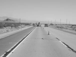
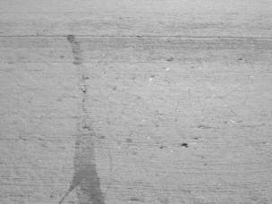
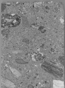
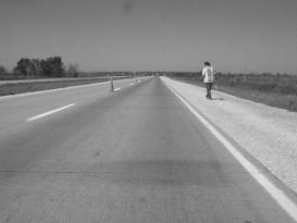
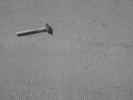
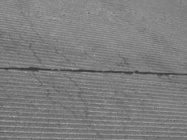
The potential MRD is characterized by map cracking over the entire pavement surface. These cracks, made up of multiple interconnecting surface cracks, form a honeycomb pattern on the pavement surface. The cracks are generally hairline cracks but are more visible in the wheel paths because they are slightly more open. No staining or exudate was observed within or surrounding the cracks and joints. Figure 3-74 shows the typical site conditions.
Table 3-32. Summary of MRD characterization for CA-014-011.
|
Description |
Section 001 |
Comments |
|
|---|---|---|---|
|
Cracking |
Location |
Entire slab |
More prevalent in wheel paths |
|
Orientation/shape |
Honeycomb |
||
|
Extent |
Entire slab |
||
|
Crack size |
Hairline |
||
|
Staining |
Location |
None |
|
|
Color |
n/a |
||
|
Exudate |
Present |
None |
|
|
Color |
n/a |
||
|
Extent |
n/a |
||
|
Scaling |
Location |
None |
|
|
Area of surface |
n/a |
||
|
Depth |
n/a |
||
|
Vibrator Trails |
Visible |
None |
|
|
Discolored |
n/a |
||
|
Distressed |
n/a |
||
|
Change in texture |
n/a |
||
|
|
|
|
(a) Section overview |
(b) Close up of observed map cracking |
Figure 3-74. Typical conditions at CA-014-011.
Core selection/Visual Inspection
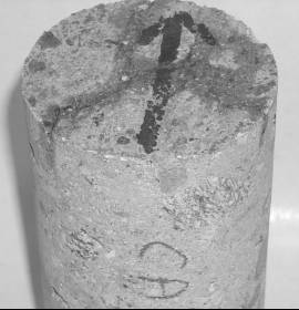
Through visual examination, the aggregate type was determined to be granitic crushed gravel. The fine aggregate was the same rock type as the coarse aggregate. In examining all pavements in this study, the flowchart for assessing the likelihood of MRD (figure II-14 in Guideline II) was used to determine if the distress is most likely an MRD. For the previous sites, this flowchart always determined that an MRD was probable and it wasn't discussed. For this site, figure II-14 yielded the answer of probably not an MRD. Although a map cracking pattern was observed on the pavement surface, as shown in figures 3-74(b) and 3-75, it was thought to be shrinkage cracks, given the nature of the cracks, the slow progression of the distress, and the age of the pavement (28 years). However, to be confident of our visual assessment, it was decided to examine core E in the laboratory since a definitive assessment of a possible MRD cannot be performed without examining the concrete with a stereo optical microscope.
Figure 3-75. Map cracking pattern on core CA-014-011-001E, emphasized by wetting down the surface.
The stereo optical microscope was used to examine the cracking and trace its path back into the specimen. The surface cracks pass through the paste, some go around aggregates, and some go through aggregates. Cracks are wide and irregular in cross-section near pavement surface, but narrow as the crack descends into the pavement. To image these diagnostic features, a conventional flatbed scanner hooked to a PC was used. The flatbed scanner is a convenient way to get an image that, when scanned in at high resolution (e.g., 1200-2400), can be zoomed digitally and viewed magnified on the computer monitor. This is a fast and easy way of documenting polished slabs.
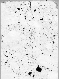
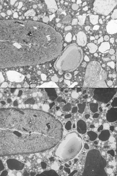
In figure 3-76, a crack is seen that runs the length of the image. It starts wide at the top and narrows as it goes deeper into the concrete, jogging around one large aggregate grain. That portion of the crack is typical of plastic shrinkage, wide and irregular at the pavement surface, where the paste was soft and cracked preferentially. The rest of the crack is more typical of drying shrinkage where much larger stresses are applied to the aggregates as the paste hardens with time. Stresses build to the point where the crack already started at the surface propagates through an aggregate and continues. Figure 3-77 is a normal scan of the same specimen. Some darkened rims are evident on the coarse aggregate, which is typical of ASR.
Figure 3-76. Inverse image of polished cross section of core
CA-014-011-001E, through pavement,
after painting the surface black and pressing white powder into the voids and
cracks (magnified 1.5x).
Figure 3-77. Same area of core CA-058-011-001E as
shown in figure 3-78,
included to show darkened reaction rims on some of the coarse aggregate (magnified
1.5x).
The sodium cobaltinitrite and barium chloride/potassium permanganate stains were applied and both were positive meaning ASR reaction products and sulfate minerals were present in the concrete. Micrographs showing ASR reactive particles and ettringite inclusions are shown below in figure 3-78. Also the phenolphthalein stain was used to determine the depth of carbonation. This slab was scanned and is shown in figure 3-79. Note the areas of deeper carbonation in the vicinity of the plastic shrinkage crack, indicating the increased permeability of the cracked surface.
|
|
|
|
(a) Yellow sodium cobaltinitrite stain for ASR gel in cracks associated with granitic coarse aggregate |
(b) Ettringite filled air voids that have picked up the purple to pink stain from the solution of barium chloride and potassium permanganate |
Figure 3-78. Results of staining test applied to core CA-058-011-001E.
This site provides an excellent case for demonstrating the value of the guidelines. First, through the rigorous field inspection, it was decided that an MRD was likely not the cause of the observed distress. The logic for this conclusion is shown in figure 3-80. But it was believed that laboratory work should be conducted to verify this conclusion. As discussed in Guideline II, to reach a diagnosis, the concrete must be observed using stereo microscopy. Because of this examination, the true nature of the surface cracking was documented, confirming the field evaluation. In addition, it was determined that there were diagnostic features of MRD, specifically ASR reaction products. Mild infilling of air voids and cracks with ettringite was also observed but not considered significant.
Having performed the necessary laboratory analyses and applying the diagnostic flowcharts, no possible MRDs were identified in CA-058-011. To finalize the diagnosis, the diagnostic tables were consulted. From the tables only two possible distresses were identified, including ASR and sulfate attack. The diagnostic features identified in the analysis processes are listed below in table 3-33 along with their associated MRD type and significance as related to this pavement. A brief discussion follows of each possible MRD identified in the laboratory analysis:
Figure 3-79. Phenolphthalein stained polished slab, showing
carbonation along plastic shrinkage crack (magnified 1.5x).
Figure 3-80. Flowchart for assessing the likelihood of MRD
causing the observed distress in the pavement as applied to CA-014-011.
ASR - ASR is certainly occurring in this pavement, but at this time there is little to no distress resulting from ASR. Additionally, there are no cracks associated with the ASR reaction products found in this concrete. These reaction products are filling adjacent voids and cracks within the aggregate. It is thus concluded that the ASR is not currently deleterious and is not a major contributor to the distress of this pavement at this time. Monitoring the pavement condition over time will demonstrate whether this distress is progressive, possibly helping engineers in planning maintenance schedules if the ASR does become deleterious.
Sulfate Attack - This is highly unlikely as the only signs of sulfate attack was some moderate infilling of air voids, perfectly normal in good quality concrete. Also, this pavement was constructed using Type II modified cement that helps to prevent sulfate attack at a moderate exposure level. Sulfate attack is not a major contributor to the distress of this pavement at this time.
In summary, applying the guidelines as proposed provided information for engineers that can help establish a maintenance program for this pavement, thereby extending its life. Specifically, shrinkage cracks propagating with time and applied load are the most probable cause of the distress. As the concrete becomes more permeable as a result of the cracking, opportunistic MRDs occur such as ASR. Some mitigation of ASR may be appropriate.
|
Diagnostic |
Method of Characterization |
Associated with MRD Type |
Significance |
|---|---|---|---|
|
Map cracking without exudate |
Visual |
ASR |
Low |
|
ASR reaction products in voids |
Visual |
Low |
|
|
Reaction rims on aggregates |
Visual |
Low |
|
|
Some sulfate deposits in cracks and voids |
Visual |
Sulfate attack |
Low |
This project is located on SR 2 in Iowa near the Nebraska border; the closest city to the project site is Nebraska City, Nebraska. The Iowa DOT indicated that the pavement surface had a slight map cracking pattern over about 60 percent of the pavement area. This project was thus selected as a secondary test site in the wet-freeze climatic region. This area receives approximately 760 mm of precipitation per year and has a freezing index of 580 oC-days.
The project, located in both the eastbound and westbound lanes from MP 2.09 to 3.59, is situated on a four-lane divided highway. The project was constructed in 1986. The pavement cross section includes a 240-mm JPCP and a 150-mm granular base course. The transverse joints are skewed at a 1:6 ratio, spaced at 6.1-m intervals, and contain 32-mm dowel bars for load transfer. The longitudinal and transverse joints are both sealed with a hot-pour sealant. The inside and outside shoulders, which are surfaced with AC, are 3.0 and 1.2 m wide, respectively. Specific design features for the project are summarized in table 3-34.
Table 3-34. Summary of design features for IA-002-002.
|
Category |
Design Feature |
Description |
|---|---|---|
|
General Information |
Project limits |
MP 2.09 - 3.59 |
|
Highway type |
Divided |
|
|
Number of lanes |
4 |
|
|
Direction |
Eastbound/westbound |
|
|
Construction date |
1986 |
|
|
Cumulative ESALs |
> 2,500,000 |
|
|
Pavement Cross Section |
Pavement type |
JPCP |
|
PCC slab thickness |
240 mm |
|
|
Base |
150-mm granular |
|
|
Subbase |
||
|
Subgrade type |
Glacial clay |
|
|
Transverse Joint |
Joint spacing |
6.1 m |
|
Joint skew |
1:6 |
|
|
Load transfer |
32-mm dowels |
|
|
Sealant type |
Hot-pour |
|
|
Longitudinal Joint |
Load transfer |
|
|
Sealant type |
Hot-pour |
|
|
Outer Shoulder |
Surface type |
AC |
|
Width |
3.0 m |
|
|
Inner Shoulder |
Surface type |
AC |
|
Width |
1.2 m |
|
|
Climatic Conditions1 |
Region |
Wet-nonfreeze |
|
Annual precipitation |
760 mm |
|
|
Freezing index |
580oC-days |
1 Climatic data are for Omaha, Nebraska.
Two sections were selected for survey within this project, both of which are located in the westbound, outer traffic lane. Section 001 begins at Station 1513+60 and Section 002 begins at Station 1495+00. Both sections are located approximately at grade.
The performance of each section is summarized in tables 3-35 and 3-36. It is
observed from these tables that both sections are performing similarly. Section
001 contains two transverse cracks-one low severity and one medium severity-and
Section 002 contains only one low-severity transverse crack. Short longitudinal
cracks, which appear to be more than surface cracks, are also present throughout
both sections. These cracks are generally confined to the wheel paths. Spalling
is exhibited on a few transverse joints but is limited to low severity. The
ride quality is not affected by the faulting.
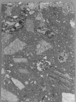
A characterization of potential MRD was conducted in the field to assist in the diagnosis of the type and cause of the distress. The potential MRD on both sections is the presence of short longitudinal cracks throughout the sections. These cracks are generally confined to the wheel paths and in many cases initiate at a transverse joint. There is some slight staining, which is brownish-gray in appearance, around transverse joints and in the wheel paths. There is no exudate observed at the cracks. Table 3-37 provides a summary of the MRD characteristics for this project. Figure 3-81(a) shows staining along longitudinal cracks and at the transverse joints. Figure 3-81(b) shows closeup views of the hairline cracks. Additional site conditions are shown in figure 3-82.
Core Selection/Visual Inspection
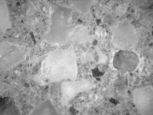
The distresses observed at both sections were similar, and appeared to be concentrated at the joints. Core A was selected from Section 001 for analysis. Core A exhibited hairline cracking at the pavement surface, and a large crack near the base running parallel to the subbase contact. Figure 3-83 shows a polished slab from core A. Other than the visible cracks, the concrete seemed in good condition. The coarse aggregate consisted of a blend of a quarried limestone and pink granite.
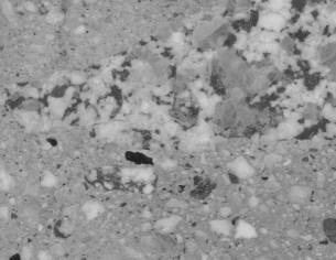
The most striking feature of the concrete was the abundance of small, entrained
air voids, as shown in figure 3-84. Although the concrete did contain a large
percentage of air, the specific surface and spacing factors were within reasonable
values. A summary of the Modified Point Count is included in table 3-38. There
was moderate infilling of the void structure by secondary ettringite. Some isolated
alkali-silica gel deposits were observed with some of the fine aggregate particles.
The gel deposits were found filling air voids near the reactive particles, and
were not associated with any cracking. The coarse aggregates were intact, and
did not appear to be reactive.
Table 3-35. Summary of pavement condition surveys for IA-002-002-001.
|
Distress Type |
Distress |
Severity Level |
Comments |
|||
|---|---|---|---|---|---|---|
|
Low |
Moderate |
High |
||||
|
Cracking |
Corner Breaks |
number |
0 |
0 |
0 |
|
|
Longitudinal Cracking |
linear meters |
14.0 |
0.0 |
0.0 |
||
|
Transverse Cracking |
number of cracks |
1 |
1 |
0 |
||
|
linear meters |
0.2 |
3.7 |
0.0 |
|||
|
percent of slabs |
8 |
|||||
|
Transverse Joints |
Sealant |
good condition |
hot-pour sealant |
|||
|
Spalling |
number |
5 |
0 |
0 |
||
|
linear meters |
1.5 |
0.0 |
0.0 |
|||
|
Faulting |
millimeters |
1.1 |
measured at 0.30 m |
|||
|
millimeters |
0.8 |
measured at 0.75 m |
||||
|
Width |
millimeters |
10.5 |
||||
|
Long. Joints |
Sealant |
good condition |
hot-pour sealant |
|||
|
Spalling |
linear meters |
0.0 |
0.0 |
0.0 |
||
|
Shoulder Dropoff |
millimeters |
26.8 |
||||
|
Surface Conditions |
Map Cracking |
number of slabs |
0 |
|||
|
square meters |
0.0 |
|||||
|
Scaling |
number of slabs |
0 |
||||
|
square meters |
0.0 |
|||||
|
Polished Aggregate |
square meters |
0.0 |
||||
|
Popouts |
number/sq. meter |
0.0 |
||||
|
Other |
Blowups |
number |
0 |
|||
|
Flexible Patches |
number |
0 |
0 |
0 |
||
|
square meters |
0.0 |
0.0 |
0.0 |
|||
|
Rigid Patches |
number |
0 |
0 |
0 |
||
|
square meters |
0.0 |
0.0 |
0.0 |
|||
|
Pumping/Bleeding |
number |
0 |
||||
|
linear meters |
0.0 |
|||||
Table 3-36. Summary of pavement condition surveys for IA-002-002-002.
|
Distress Type |
Distress Measure |
Severity Level |
Comments |
|||
|---|---|---|---|---|---|---|
|
Low |
Moderate |
High |
||||
|
Cracking |
Corner Breaks |
number |
0 |
0 |
0 |
|
|
Longitudinal Cracking |
linear meters |
3.0 |
0.0 |
0.0 |
||
|
Transverse Cracking |
number of cracks |
1 |
0 |
0 |
||
|
linear meters |
1.5 |
0.0 |
0.0 |
|||
|
percent of slabs |
4 |
|||||
|
Transverse |
Sealant |
good condition |
hot-pour sealant |
|||
|
Spalling |
number |
1 |
0 |
0 |
||
|
linear meters |
0.3 |
0.0 |
0.0 |
|||
|
Faulting |
millimeters |
1.0 |
measured at 0.30 m |
|||
|
millimeters |
0.8 |
measured at 0.75 m |
||||
|
Width |
millimeters |
10.5 |
||||
|
Long. Joints |
Sealant |
good condition |
hot-pour sealant |
|||
|
Spalling |
linear meters |
0.0 |
0.0 |
0.0 |
||
|
Shoulder Dropoff |
millimeters |
22.4 |
||||
|
Surface |
Map Cracking |
number of slabs |
0 |
|||
|
square meters |
0.0 |
|||||
|
Scaling |
number of slabs |
0 |
||||
|
square meters |
0.0 |
|||||
|
Polished Aggregate |
square meters |
0.0 |
||||
|
Popouts |
number/sq. meter |
0.0 |
||||
|
Other |
Blowups |
number |
0 |
|||
|
Flexible Patches |
number |
0 |
0 |
0 |
||
|
square meters |
0.0 |
0.0 |
0.0 |
|||
|
Rigid Patches |
number |
0 |
0 |
0 |
||
|
square meters |
0.0 |
0.0 |
0.0 |
|||
|
Pumping/Bleeding |
number |
0 |
||||
|
linear meters |
0.0 |
|||||
|
Description |
Section 001 |
Section 002 |
Comments |
|
|---|---|---|---|---|
|
Cracking |
Location |
Wheel paths |
Wheel paths |
Most cracks initiate at joints |
|
Orientation/shape |
Parallel to longitudinal joint |
Parallel to longitudinal joints |
||
|
Extent |
Wheel paths |
Wheel paths |
||
|
Crack size |
Hairline |
Hairline |
||
|
Staining |
Location |
Joints/wheel paths |
Joints/wheel paths |
|
|
Color |
Brownish-gray |
Brownish-gray |
||
|
Exudate |
Present |
None |
None |
|
|
Color |
n/a |
n/a |
||
|
Extent |
n/a |
n/a |
||
|
Scaling |
Location |
None |
None |
|
|
Area of surface |
n/a |
n/a |
||
|
Depth |
n/a |
n/a |
||
|
Vibrator Trails |
Visible |
None |
None |
|
|
Discolored |
n/a |
n/a |
||
|
Distressed |
n/a |
n/a |
||
|
Change in texture |
n/a |
n/a |
||
|
|
|
|
(a) Staining along longitudinal cracks |
(b) Staining along transverse joints |
Figure 3-81. Site conditions at IA-002-002.
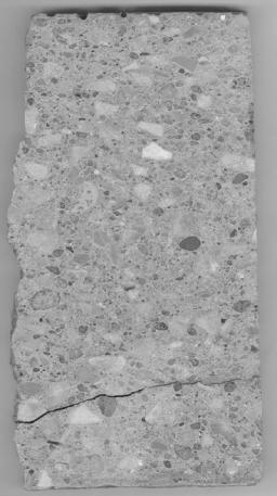
Figure 3-83. Polished slab from core IA-002-002-001A. The
irregular surface along the left-hand side
of the core is a cross-sectional view of the transverse joint texture.
Table 3-38. Air-void characteristics of core IA-002-002-001A as determined by ASTM C457.
|
Original |
Existing |
|||
|---|---|---|---|---|
|
Core |
Air Content |
Spacing Factor |
Air Content |
Spacing Factor |
|
Site 1 Core C |
8.73 |
0.213 |
8.59 |
0.216 |
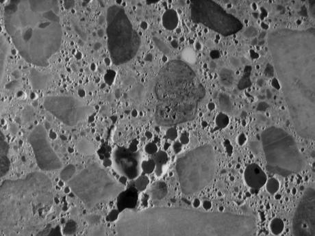
Figure 3-84. Stereo micrograph showing air void structure of IA-002-002-001A, magnified 7.5x.
Petrographic Optical Microscopy
Areas observed to contain reactive fine aggregate particles were prepared in thin section. Figure 3-85 shows a reactive particle that has undergone dissolution, cracking, and the reaction product has filled some neighboring air voids. The reactive particles, which appear to be volcanic in origin with phenocrysts in a very fine matrix, are likely to have originated from much further west, and been brought to the area by the Missouri River. The air-void structure has experienced limited infilling by secondary ettringite.
Figure 3-85. Reactive fine aggregate particle with alkali-silica
gel filled air voids as viewed in thin section.
Top image is transmitted plane polarized light, bottom image is in epifluorescent
mode, magnified 20x.
Although the concrete exhibits signs of distress such as hairline longitudinal cracking with staining in addition to staining at the transverse joints, it is still performing well. Some ASR was present in the fine aggregate, although it did not seem to be associated with any cracking. The air-void content was unusually high, over 8 percent, with an abundance of small-entrained air voids that were sometimes coalesced into dense groupings.
Having performed the described laboratory analyses and applied the diagnostic flowcharts, as shown in figures 3-86 through 3-90, three possible MRDs were identified in IA-002-002, including paste freeze-thaw, ASR and sulfate attack with none being dominant or extensive. To finalize the diagnosis, the diagnostic tables were consulted. The diagnostic features identified in the analysis processes are listed below in table 3-39 along with their associated MRD type and significance as related to this pavement. A brief discussion of each distress is given below.
ASR - The ASR occurring in this pavement was not extensive and did not seem to related to any of the observed cracking. As a result, ASR is not considered to be a major cause of the observed MRD. This does not rule out ASR in its early stages as being present.
Paste Freeze-Thaw - The only diagnostic feature of paste freeze-thaw present was the marginal air-void system in terms of the measured Powers spacing factor. This is considered to be a diagnostic feature of low significance given the fact that no other diagnostic feature of paste freeze-thaw was seen. As a result, paste freeze-thaw is not considered to be a major cause of the observed distress.
Sulfate Attack - The only diagnostic feature of sulfate attack was ettringite infilling in entrained air voids. This was considered a low significance diagnostic feature for a variety of reasons. First, ettringite deposits by themselves are not diagnostic of sulfate attack. Second, the amount of infilling was limited, not extensive. Finally, no other diagnostic feature of sulfate attack was observed. Therefore, sulfate attack is ruled out as a major cause of the observed distress.
In summary, the exact nature of the observed distress is not known. The unusual air-void structure may be a contributor but the exact mechanism could not be discerned from this analysis. It is noted that the concrete had a very fine coarse aggregate grading, which may also be a contributing factor but, again, no evidence of a specific mechanism for the observed distress was seen related to this gradation. The guidelines do help rule out the obvious types of MRD but in the end, this is an example of a pavement that cannot be absolutely diagnosed using the developed guidelines.
Figure 3-86. Flowchart for assessing the likelihood of MRD
causing the observed distress in the pavement as applied to IA-002-002.
|
Possible Distress |
Present |
Additional Information |
|
|---|---|---|---|
|
Error in Mix Proportioning |
Yes |
No |
See Recommended Literature |
|
Poor Placement |
Yes |
No |
See Recommended Literature |
|
Poor Finishing/Curing |
Yes |
No |
See Recommended Literature |
|
Poor Steel Placement |
Yes |
No |
See Recommended Literature |
|
Carbonation at Depths > 5-10 mm |
Yes |
No |
See Recommended Literature |
Figure 3-87. Flowchart for assessing general concrete properties based on visual examination as applied to IA-002-002.
|
Possible Distress |
Present |
Additional Information |
|
|---|---|---|---|
|
Shrinkage Cracks or Sample Preparation Cracks |
Yes |
No |
See Recommended Literature |
|
Paste Freeze-Thaw |
Yes |
No |
Table II-2 |
|
Aggregate Freeze-Thaw |
Yes |
No |
Table II-3 |
|
Sulfate Attack |
Yes |
No |
Table II-4 |
|
Deicer Attack |
Yes |
No |
Table II-5 |
|
Secondary Deposits
|
Yes |
No |
Figure 3-90 |
Figure 3-88. Flowchart for assessing the condition of the concrete paste as applied to IA-002-002.
|
Possible Distress |
Present |
Additional Information |
|
|---|---|---|---|
|
Natural Cracking of Aggregate |
Yes |
No |
See Recommended Literature |
|
Sample Preparation Cracks |
Yes |
No |
See Recommended Literature |
|
Aggregate Freeze Thaw |
Yes |
No |
Table II-3 |
|
Natural Weathering of Aggregates |
Yes |
No |
See Recommended Literature |
|
Alkali-Silica Reaction |
Yes |
No |
Table II-6 |
|
Alkali-Carbonate Reaction |
Yes |
No |
Table II-7 |
|
Secondary Deposits
|
Yes |
No |
Figure 3-90 |
Figure 3-89. Flowchart for assessing the condition of the concrete aggregates as applied to IA-002-002.
|
Possible Distress |
Present |
Additional Information |
|
|---|---|---|---|
|
Sulfate Attack |
Yes |
No |
Table II-4 |
|
Deicer Attack |
Yes |
No |
Table II-5 |
|
Alkali-Silica Reaction |
Yes |
No |
Table II-6 |
|
Alkali-Carbonate Reaction |
Yes |
No |
Table II-7 |
| Corrosion of Embedded Steel |
Yes |
No |
Table II-1 |
Figure 3-90. Flowchart for identifying infilling materials in cracks and voids as applied to IA-002-002.
|
Diagnostic |
Method of |
Associated with |
Significance |
|---|---|---|---|
|
ASR reaction products in voids |
Petrographic OM |
ASR |
Low |
|
Significant sulfate deposits in cracks and voids |
Staining |
Sulfate attack |
Low |
|
Inadequate air-void system |
Stereo OM |
Paste freeze-thaw |
Low |
[1] Climatic data are for Los Angeles, California.