U.S. Department of Transportation
Federal Highway Administration
1200 New Jersey Avenue, SE
Washington, DC 20590
202-366-4000
Federal Highway Administration Research and Technology
Coordinating, Developing, and Delivering Highway Transportation Innovations
 |
| This report is an archived publication and may contain dated technical, contact, and link information |
|
Publication Number: FHWA-RD-03-047 Date: July 2003 |
Previous | Table of Contents | Next
This chapter summarizes various case studies involving the use of lithium in both new and existing concrete. This comprehensive summary provides relevant information on materials, mixture proportions, supporting laboratory testing (if available), application techniques (for treating existing concrete), and field performance for each of the trials. Information gathered and lessons learned from these case studies are incorporated into the guidelines for using lithium (chapter 5).
4.2.1 Lomas Boulevard, Albuquerque, NM (1992)
Construction of Experimental Pavement
An experimental pavement consisting of the westbound approach lanes to a bridge carrying Lomas Boulevard (State Route 352) over U.S. Interstate 40 in Albuquerque, NM, was constructed in June 1992. The 3-lane pavement is 155 m long and 11 m wide. Eleven different concrete mixtures were used to construct the pavement, to evaluate different methods for preventing ASR. Reactive aggregate (sand and gravel) from two local sources, namely the Shakespeare and Placitas pits, were used in combination with either fly ash or LiOH as summarized in table 10.
| Source of Reactive Aggregate | Mix No. | Preventive Measure |
|---|---|---|
| Shakespeare Pit | 1 | 1.0% LiOH |
| 2 | 0.5% LiOH | |
| 3 | LomarTM admixture | |
| 4 | Class F Fly Ash | |
| 5 | Class C Fly Ash | |
| 5 | Class C Fly Ash | |
| 6 | None (Control) | |
| 7 | Blend of Class F and C Fly Ash | |
| Placitas Pit | 8 | Class F Fly Ash |
| 9 | None (Control) | |
| 10 | 1.00% LiOH | |
| 11 | Class C Fly Ash |
The total cementitious material content of the concrete mixtures was nominally 395 kg/m3 with five of the mixtures containing fly ash at a nominal replacement level of 20 percent. The cement was reported to have an alkali content of approximately 0.55 percent Na2Oe (Stark et al. 1993). The Class F fly ash was from the Cholla Generating Station in Phoenix, AZ, and the Class C fly ash was from the Tolk Generating Station in the Texas Panhandle. One mixture contained a 50-50 blend of Class F and Class C fly ash. In this case, the "C ash" was from the same source, but the "F ash" was from Escalente Generating Station (according to mixture data sheets). The water-cementitious materials ratio (w/cm) of these mixtures was generally in the range of 0.40.
The lithium was added as a dry powder of LiOH•H2O and dosed at rates of either 0.5 percent or 1.0 percent by mass of portland cement. Assuming the alkali content of the cement to be 0.55 percent Na2Oe, these lithium doses yield lithium-alkali molar ratios of Li:(Na + K) = 0.67 and 1.34 in the concrete with 0.5 percent and 1.0 percent LiOH•H2O, respectively.
To ensure adequate dispersion of the LiOH•H2O powder, the mixing water and appropriate dose of powder were batched into the trucks the night before the concrete was placed. The use of LiOH had no discernable effect on the slump or air content of the concrete, nor did it impact the placing or finishing operations.
After placing the experimental pavement, the aggregates were tested in combination with the fly ashes and low-alkali cement (0.18 percent Na2Oe) using the accelerated mortar bar test (ASTM C 1260), yielding the results shown in table 11. Aggregate-LiOH combinations were tested using ASTM C 227, but no data from these tests have been reported. The test data in table 11 confirm the high reactivity of both aggregate sources and the inferior performance of Class C fly ash compared to Class F fly ash in controlling expansion.
| Aggregate | Fly Ash | Expansion (%) | |
|---|---|---|---|
| 7 days | 14 days | ||
| Shakespeare Pit | None | 0.580 | - |
| None | 0.502 | - | |
| Class C | 0.405 | - | |
| Class F and C | 0.052 | 0.125 | |
| Class F | 0.017 | 0.045 | |
| Placitas Pit | None | 0.575 | - |
| None | 0.511 | - | |
| Class C | 0.400 | - | |
| Class F | 0.015 | 0.055 | |
Table 11. Results from ASTM C 1260 Tests (Stark et al. 1993).
Subsequent Investigations
Concrete cores were taken from the different sections after 2 and 3 years, and were tested to determine the elastic (static) modulus. The results from these tests, shown in figure 14, do not indicate signs of progressive deterioration (i.e. there was no reduction in modulus between 2 and 3 years), although the static modulus of the concrete with Class C fly ash and Shakespeare aggregate (mix #5) was significantly lower than the other mixtures.
Cores taken at 2 years were also subjected to limited petrographic examination, and a summary of the results is presented in table 12. Only concrete containing Class C fly ash showed any visual signs of damage when lapped samples were viewed under a stereobinocular microscope.
Figure 14. Elastic Modulus of Concrete Cores from Lomas Boulevard.
| Concrete Mixture | Cores at 2 Years | Cores at 4 Years | ||||
|---|---|---|---|---|---|---|
| Number of Reaction Sites | Damage | Uranyl Acetate | LANL Stain | Petrography | Overall | |
| Shakespeare Aggregate | ||||||
| 1.1.0% LiOH | 5 | No | 3 | 4 | 4 | 11 |
| 2. 0.5% LiOH | 10 | No | 4 | 4 | 4 | 12 |
| 3.Lomar | 30 | Yes | 2 | 2 | 2 | 6 |
| 4.Class F Fly Ash | 15 | No | 4 | 4 | 3 | 11 |
| 5.Class C Fly Ash | 30 | Yes | 1 | 1 | 1 | 3 |
| 6.Control | 5 | No | 4 | 3 | 3 | 10 |
| 7.Blend of F and C Ash | Many | Yes | 3 | 3 | 3 | 9 |
| Placitas Aggregate | ||||||
| 8.Class F Fly Ash | Many | No | 2 | 2 | 3 | 7 |
| 9.Control | 10 | No | 4 | 4 | 3 | 11 |
| 10.1.00% LiOH | None | No | 4 | 3 | 4 | 11 |
| 11. Class C Fly Ash | Many | Yes | 1 | 2 | 2 | 5 |
Further cores were extracted in 1996 (at 4 years), and these samples were subjected to a detailed petrographic examination (Sherman and Krauss, 1997). Thin-section microscopy and staining techniques using uranyl acetate and Los Alamos National Laboratory (LANL) stain were used together with visual observations of the reacted particles, gel amount, and distress in the form of microcracking. The results of these studies, compared with the observations made at 2 years, are presented in table 12. The observations made during the later examination were ranked using a numerical scale (see table 12), which can be interpreted as shown in table 13.
Generally, the mixtures containing Class C fly ash showed the most signs of reactivity and those containing LiOH the least. However, the observations reported were largely qualitative, and it is not possible to provide a more objective ranking of the different mixtures' performance.
Further visual inspections of the site were made in February 1999 and April 2001. Figure 15 shows a general view of the experimental pavement looking westward. Figure 16 through figure 19 show the 4 sections with Placitas aggregate in February 1999. Significant cracking was evident in both the control section and the section with Class C fly ash at this time, and the extent of damage appeared to be substantially more severe in the fly ash concrete. The concrete sections containing Class F fly ash or 1 percent LiOH•H2O appeared to be in good condition, with little visible cracking at the surface at the age of 7 years. However, after 2 more years, some cracking appeared on the surface of the fly ash concrete close to the sawn-cut edge of the slab (see figure 20).
| Rank | Uranyl Acetate | LANL Stain | Petrography |
|---|---|---|---|
| 1 (Worst) | Highly positive | Much yellow stained gel and aggregate | Many reacted particles, much gel, and distress |
| 2 | Abundant glowing areas | Yellow stained gel and aggregate | Many reacted particles and much gel |
| 3 | Some glowing areas | Yellow aggregate | Some reacted particles and gel |
| 4 (Best) | Mostly negative | Mostly negative | Few particles and little gel |
The control concrete containing Shakespeare aggregate and the sections with either Class C fly ash or a blend of F and C fly ash admixture all exhibited significant cracking when examined at 7 and 9 years. The concrete with the Class F fly ash and either 0.5 percent or 1.0 percent LiOH•H2O show no significant cracking at the same ages.
More cores were taken from the experimental pavement in December 2001 and these will be subjected to the following tests:
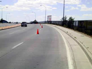
Figure 15. General View of Lomas Boulevard Experimental Pavement.
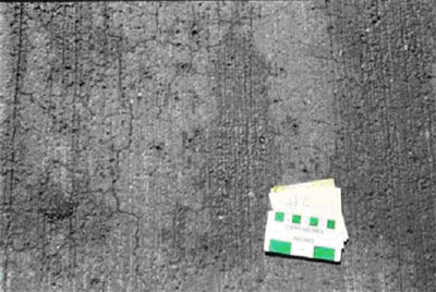
Figure 16. Control Section with Placitas-February, 1999.
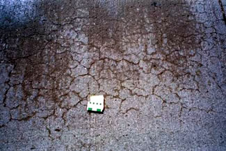
Figure 17. Section with Class C Fly Ash and Placitas-February, 1999.
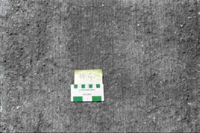
Figure 18. Section with Class F Fly Ash and Placitas-February, 1999.
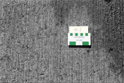
Figure 19. Section with 1 Percent LiOH and Placitas-February, 1999.
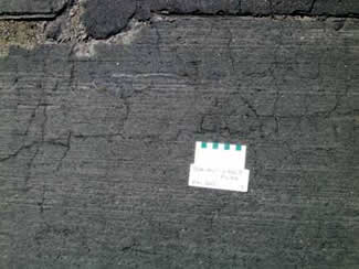
Figure 20. Section with Class F Fly Ash and Placitas-May, 2001.
In summary, the concrete mixtures containing LiOH (at both doses), together with highly reactive New Mexico aggregates, appear to be performing very well after 10 years service. Although only small differences were observed between the visual appearance of these concrete mixtures and those containing approximately 20 percent of a Class F fly ash, the lithium appears to have been slightly more effective in controlling cracking. However, continued monitoring of this site is required to determine whether the lithium continues to show improved performance over the Class F fly ash.
All the mixtures without fly ash had a total cementitious material content of 350 kg/m3. The fly ash mixtures contained 315 kg/m3 of portland cement with varying amounts of fly ash. The water-cementitious material (w/cm) ratio of the mixtures was 0.44, except for mix #11 where w/cm = 0.42. LiOH was added in the form of an aqueous solution containing 8.75 percent LiOH by mass to achieve the target lithium-alkali molar ratios. In mix #12, which contained LiOH in combination with Class F fly ash, the lithium was dosed at the same rate as mix #2 (i.e. assuming the fly ash to contribute the same amount of alkali as the cement it replaced).
4.2.2 Lakawanna Valley Industrial Highway, PA (1997)
The Lackawanna Valley Industrial Highway is a new four-lane highway built in May 1997 in Lackawanna County in northeastern Pennsylvania. A section of this highway was constructed using reactive greywacke aggregate, high-alkali cement, and various preventive measures to assess SHRP recommendations for controlling ASR (Thomson and Stokes, 1999; Thomson, 2000). A photograph of the experimental pavement section is shown in figure 21.
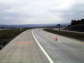
Figure 21. Lackawanna Valley Industrial Highway Experimental Section.
Twelve different concrete mixtures were used in the construction of the experimental section; one of these was a control mixture with high-alkali cement (0.86 percent Na2Oe) and the remaining 11 mixtures used various approaches to mitigate expansion. The preventive measures adopted are summarized in table 14.
The different systems were tested using the Pyrex mortar bar test (ASTM C 441) and the accelerated mortar bar test (ASTM C 1260), and the test results are also included in table 14.
The test data in table 14 clearly indicate the coarse and fine aggregates to be potentially reactive and demonstrate that the use of sufficient levels of lithium, fly ash, or slag are all effective in controlling damaging expansion. Note that the accelerated mortar bar test (ASTM C 1260), as it exists in its standard form, is not suitable for the purpose of evaluating lithium or low-alkali cement.
| Mix # | Preventive Measure | C 441 | C 1260 | |
|---|---|---|---|---|
| Coarse Aggregate | Fine Aggregate | |||
| 1 | None (Control) | 0.432 | 0.402 | 0.257 |
| 2 | LiOH: [Li]:[Na + K] = 0.75 | 0.014 | - | - |
| 3 | LiOH: [Li]:[Na + K] = 1.00 | 0.014 | - | - |
| 4 | LiOH: [Li]:[Na + K] = 1.25 | 0.011 | - | - |
| 5 | Low-alkali cement (0.37% Na2Oe) | 0.299 | - | - |
| 6 | 25% GGBF Slag | 0.187 | 0.301 | 0.127 |
| 7 | 40% GGBF Slag | 0.026 | 0.113 | 0.034 |
| 8 | 50% GGBF Slag | 0.024 | 0.065 | 0.016 |
| 9 | 15% Class F Fly Ash | 0.239 | 0.247 | 0.074 |
| 10 | 20% Class F Fly Ash | 0.221 | 0.156 | 0.046 |
| 11 | 25% Class F Fly Ash | 0.155 | 0.101 | 0.017 |
| 12 | 15% Class F Fly Ash + LiOH [Li]:[Na + K] = 0.75 | 0.008 | - | - |
Detailed visual inspection of the experimental pavement is conducted periodically. Figure 22 shows some very fine cracking developing on the 15 percent Class F fly ash mix after 4 years. Several other sections showed similar cracking, however, all of the concrete was in generally excellent condition at this age. The conditions of the concrete also are being monitored using impact echo techniques (figure 23); little significant change in response has been observed to date.

Figure 22. Lackawanna Valley Industrial Highway Experimental Pavement-15
percent Fly Ash (Mix #9)-May, 2001.
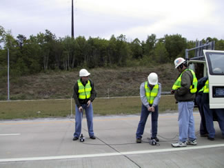
Figure 23. Impact Echo Testing-Lackawanna Valley Industrial Highway Experimental
Pavement.
4.2.3 U.S. I-90, Oacoma, SD (1996)
In June 1996, the South Dakota Department of Transportation (DOT) replaced a 13.36-km long section of asphalt pavement with a continuously reinforced concrete pavement and jointed plain concrete pavement. A highly reactive sand and a slowly reactive quartzite coarse aggregate were used together with a series of 14 different concrete mixtures incorporating various measures to control expansion due to ASR (Johnston, 2001). Details of the mixtures are summarized in table 15.
The cement used in all of the mixtures was a Type V low-alkali (0.55 percent Na2Oe) cement. The test sections are being monitored by means of visual examination, impact echo, and modulus of elasticity (on cores). The LiOH and LiNO3 were added as aqueous solutions containing 8.75 percent LiOH and 30 percent LiNO3 by mass, respectively. Decrepitated spodumene represents an intermediate stage in the lithium extraction process of the ore spodumene. Spodumene ore normally is crushed and fired in a kiln to "untie" the lithium prior to its extraction. The material at this stage is known as decrepitated spodumene and is essentially an amorphous alumino-silicate that contains significant quantities of available lithium. A detailed description of the material and its efficacy in controlling ASR in laboratory tests has been presented by Thomas and Stokes (1999).
| Mix # | Cementitious Material (kg/m3) | Preventive Measure | ||
|---|---|---|---|---|
| Type V Cement | Class F Fly Ash | Type | Dose (L/m3) | |
| 1 | 356 | - | LiOH Solution | 9.90 |
| 2 | 356 | - | LiOH Solution | 12.87 |
| 3 | 356 | - | LiOH Solution | 15.84 |
| 4 | 356 | - | LiNO3 Solution | 4.95 |
| 5 | 356 | - | LiNO3 Solution | 7.43 |
| 6 | 356 | - | LiNO3 Solution | 9.90 |
| 7 | 356 | - | LiNO3 Solution | 12.38 |
| 8 | 303 | 66.4 | LiNO3 Solution | 2.48 |
| 9 | 303 | 66.4 | LiNO3 Solution | 4.95 |
| 10 | 356 | - | Decrepitated Spodumene | 10.9 kg |
| 11 | 356 | - | Decrepitated Spodumene | 21.8 kg |
| 12 | 303 | 66.4 | Decrepitated Spodumene | 10.9 kg |
| 13 | 356 | - | - | - |
| 14 | 303 | 66.4 | - | - |
All of the concrete appeared to be in good condition when inspected in June 2001, and there has been no progressive change in the in-situ response of the concrete to impact echo or in the static modulus of core samples. A photograph of the site is shown in figure 24.
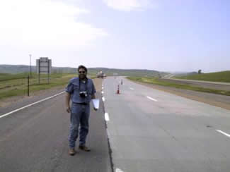
Figure 24. Experimental Pavement on U.S. I-90 near Oacoma, SD.
4.2.4 Coyote Springs Bridge, NM (2000)
This bridge, shown in Figure 25, was built in 1999, using highly reactive aggregate from the Placitas quarry near Albuquerque, NM. The concrete was produced using a combination of Class F fly ash and lithium.
During an inspection of the bridge in August 2001, cracking was observed on the surface of the deck. A photograph showing the nature of the cracking observed is shown in figure 26. This type of cracking was visible on many parts of the exposed bridge deck. Although this type of random or map-pattern cracking with associated damp staining of the cracks is observed frequently in concrete structures affected by ASR, the feature is not reliably diagnostic of this form of deterioration. Such cracking may form due to other processes, such as plastic shrinkage during construction or drying shrinkage during the early stages of exposure. The role of ASR can be determined only by petrographic examination of the samples removed from the structure.
Two cores were taken from the structure for petrographic examination and chemical analysis to determine the lithium content. The average lithium content was determined to be 0.0097 percent and 0.0101 percent for the 2 cores. This equates to a lithium dosage of between 6.5 to 7.0 liters (L) of LiNO3 solution per cubic meter of concrete, assuming the solution to be 30 percent LiNO3.
The petrographic examination revealed minor evidence of internal microfracturing of some aggregate particles and of reaction rims around other particles, however, there was no indication of an expansive reaction that could lead to internal microcracking of the concrete. To determine that ASR has led to the internal disruption of concrete requires evidence of sites of expansive reaction, i.e., the occurrence of features that provide direct evidence of reaction and production of expansive forces. Such features take the form of reactive aggregate particles showing cracking internally or at the cement/aggregate interface, with cracks propagating into the surrounding matrix and cracks filled or partially filled with gel. No such features were evident in the sections examined. Indeed, very few cracks were found in the cement paste matrix, and these were largely confined to the exposed surface of the concrete. Spherical fly ash particles were found in the cement paste fraction of the cores, but no attempt was made to quantify the replacement level of replacement. Further monitoring is required to determine whether there is progressive deterioration of the structure due to ASR.
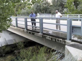
Figure 25. Coyote Springs Bridge, NM.
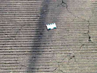
Figure 26. Cracking on Deck Surface of Coyote Springs Bridge, NM.
4.2.5 Bridge Deck Overlay, Wilmington, DE (1999)
Delaware DOT specified the use of LiNO3 in a concrete overlay for repairing a corrosion-damaged concrete bridge deck in Wilmington, Delaware. The contract involved the remov ingal, by milling, of the concrete down to the top mat of reinforcing steel and placing a dense, low-permeability overlay containing 7 percent silica fume. The concrete bridge also was suffering from ASR, and there were concerns that the new concrete might provide an additional source of alkali to stimulate further reaction in the existing concrete. The cements available in Delaware are typically high in alkali. Lithium nitrate LiNO3 solution (30 percent LiNO3) was sprayed onto the freshly milled surface prior to placing the overlay and was also used as an admixture in the concrete overlay. The sand used in the overlay was moderately reactive. The philosophy of this approach is to provide sufficient lithium to control ASR in the overlay and in the existing concrete. The latter is achieved by direct ly topical appl ying ication of the LiNO3 solution onto the substrate and also by migrati ng on of the lithium from the overlay into the substrate. Although the efficiency of penetration is not known, it is hoped that sufficient lithium will penetrate to control damaging reactions at the interface between the old and new materials, thus minimizing the risk of debonding. Figure 27 shows a photograph of the bridge deck, and Figure 28 provides a comparison of the new overlay concrete with the existing ASR-affected concrete.
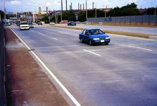
Figure 27. Bridge Deck Overlay, Wilmington, DE.
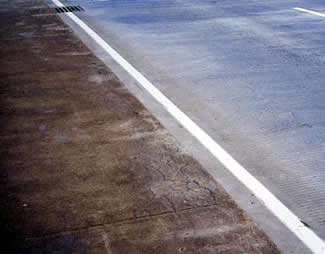
Figure 28. Comparison of Existing ASR-Affected Concrete (at left) with New Overlay Concrete (at right).
4.2.6 Bridge Deck Overlay, Lyman County, SD (2000)
The South Dakota DOT specified Lithium nitrateLiNO3 solution was specified by SDDOT as an admixture for a number of concrete bridge deck overlays placed during the repair of a 20.9-km stretch of highway in Lyman County, SD (figure 29). In addition, the bonding grout used between old and new concrete also contained LiNO3. The lithium was used for the same reasons as those discussed in the previous section (deck overlay in Delaware).
4.2.6 Bridge Deck Overlay, Lyman County, SD (2000)
The South Dakota DOT specified LiNO3 solution was specified by SDDOT as an admixture for a number of concrete bridge deck overlays placed during the repair of a 20.9-km stretch of highway in Lyman County, South DakotaSD (figure 29). In addition, tThe bonding grout used between old and new concrete also contained LiNO3. The lithium was used for the same reasons as those discussed in the previous section (deck overlay in Delaware).
Figure 29. Bridge Deck Overlay, Lyman County, SD.
The overlay concrete was produced using low-alkali cement, Class F fly ash, and 7.43 L/m3 of 30 percent LiNO3 solution, and both the sand and coarse aggregate were alkali reactive. As with the overlay placed in Delaware, the incorporatingion of LiNO3 into the concrete mixture had no noticeable impact on the concrete properties or the placing schedule.
4.2.7 Utility Transmission Towers, Corpus Christi, TX (2000)
LiNO3 was used in transmission tower footings constructed for a 40.2-km length of transmission line near Corpus Christi, Texas. The potential reactivity of the aggregates in the area called for some measure of ASR control, and the options available to the contractor were using lithium, Class F fly ash, or importing non-reactive aggregates. Lithium was chosen, because since the quality and availability of the fly ash in the region was questionable, and the costs associated with hauling aggregate were too high. The concrete mixture contained a low-alkali cement and 8.42 L/m3 of 30 percent LiNO3 solution together with moderately reactive coarse and fine aggregates. Figure 30 shows a photograph of the construction of one of the foundations.
4.2.8 Repair of Platte Winner Bridge, SD (1998)
Repair of the pile caps of the Platte Winner Bridge in South Dakota (figure 31) became necessary after severe damage was caused by heavy river ice loads during a winter storm in 1997. Petrographic examination of the concrete revealed that ASR was occurring in the 30-year old structure, and it was thought that this might have weakened the concrete, thereby exacerbating the storm damage. The concrete and grout used for repair were specified to contain LiNO3 solution to prevent ASR in the new concrete and to provide a source of lithium to the existing concrete. The concrete mixture contained low-alkali cement, a fly ash with an intermediate calcium content, and 7.43 L/m3 of 30 percent LiNO3 solution, together with slowly reactive coarse and highly reactive fine aggregates. The repair concrete had to be pumped over 60.9 m horizontally and then down 9.1 m from the bridge deck to the pile caps. The use of the lithium admixture did not affect the concrete properties and was found to be compatible with the other admixtures.
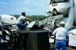
Figure 30. Utility Transmission Tower Footing in Corpus Christi, TX.
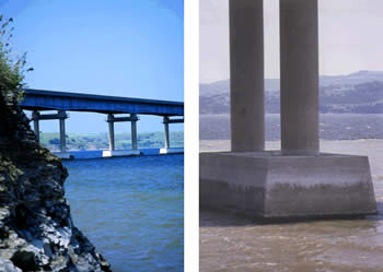
Figure 31. Repair of Pile Caps on Platte Winnder Bridge, SD.
4.3.1 Topical Applications
U.S. Route 14, Wolsey, SD (1995)
This roadway, which forms part of U.S. Route 14 near Wolsey, SD, and was constructed in 1981, is a 2-lane, 185-mm-thick jointed plain concrete pavement. Damage due to ASR was first detected in 1989, and topical lithium application was completed in October 1995. A detailed description of the project is given in Johnston et al. (2000).
The decision to use LiNo3 solution was based on concerns surrounding the possible pessimum effect associated with LiOH, i.e., if the quantity of LiOH introduced to the concrete was too low, it could have the increased the potential for expansion by raising the pH of the concrete pore solution. However, the pessimum effect has only been observed when insufficient LiOH is added to new concrete, and there is no experimental evidence to suggest similar behavior when lithium is applied to hardened concrete. A 30 percent LiNO3 solution containing a propriety blend of surfactants (to reduce surface tension effects and aid penetration) was applied at a rate of 0.16L/M2 A photograph of the spray truck is shown in figure 32. Three 150-m long sections were treated 1,2 or 3 times, achieving total applications of 0.16, 0.32, and 0.48 L/m2. Three sections of the same size were left untreated for comparison.
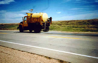
Figure 32. Topical Application of Pavement near Wolsey, SD.
Monitoring of these sections included visual assessment, modulus testing of cores, and in-situ impact echo soundings. In addition, samples were collected at different times to different times to determine the penetration depth of lithium into uncracked and cracked concrete. Modulus testing indicated little significant change in the stiffness of the treated or untreated sections 1-3 years after treatment. However, between 3 and 4 years, there was a sudden increase in the modulus of elasticity (~5 to 6 Gigapascals GPa)) for the treated sections; no change was observed for the control sections. By contrast, the impact echo measurements made 2 years after treatment showed slightly reduced frequency values in the treated sections compared with the control sections, however, these differences could be due to small differences in the pavement thickness of pavement. Interestingly, for the control sections, there was a significant reduction in the compression-wave velocity calculated from impact echo readings made on cores compared to in-situ measurements made at the same location prior to coring. Differences between measurements made in-situ and on cores were less pronounced for the treated concrete.
This change in velocity was attributed to relaxation of internal stresses in the concrete when the cores were removed (Johnston et al., 2000) -the greater change in the untreated sections may indicate increased ASR activity and, hence, internal stress. Chemical analysis to determine lithium concentration profiles showed little significant penetration of lithium into uncracked concrete approximately 10 mm below the surface 10 mm or so. However, larger quantities of lithium were detected at depths of 45 mm in concrete that was moderately cracked, although there was no correlation between the amount of lithium detected and the number of treatments.
Johnston et al. (2000) conclude that the lithium appears to have had a positive effect by reducing the distress due to ASR. However, there is little visible difference between the treated and untreated sections at this time, and continued monitoring is required to confirm these preliminary findings.
U.S. I-68, LaVale, MD (1997)
In 1986, the decks and parapets to two bridges carrying opposite lanes of U.S. I-68 over a gorge in the Appalachian Mountains were replaced. Just 10 years later, ASR was detected in the new concrete in both structures, and lithium treatment was conducted in 1997. The treatment involved a single topical application to the structure carrying the westbound lanes; the other structure was left untreated as a control. A photograph of the bridge carrying the westbound lanes is shown in figure 33. Figure 34 shows a close-up of the deck surface and the slight- to- moderate ASR cracking apparent approximately 1 year after treatment. The surface condition of the untreated deck appeared relatively unchanged, and there appeared to have been little change in the appearance of either concrete (treated and untreated) since the time of treatment.
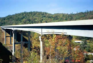
Figure 33. Bridge Carrying Westbound Lanes of U.S. I-68 Near LaVale, MD.
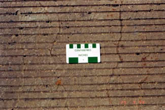
Figure 34. Cracking in 12-Year-Old Bridge Deck.
Electrical chemical injection of lithium into the deck was considered initially, but this option was later dismissed because the reinforcing steel was epoxy coated. The topical treatment involved a single pass using an application rate of 0.37 L/m2 of 30 percent LiNO3 solution. In addition to visual observations of the concrete, impact-echo monitoring is conducted periodically. Three years after treatment, there was little visible difference between the condition of the treated and untreated sections.
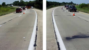
S.R Rt. 1, Bear, DE (1998)
A 6.43-km section of S.R. Route 1 near Bear, Delaware, built in 1990, began to show signs of ASR just 7 years after construction. Treatment of two sections of the affected pavement began in 1998. One of the sections was at the southern end and one at the northern end of the project, and control sections were set aside for each project. The treatment to date has involved a total of 6 spray applications (2 per year), each at a rate of 0.24 L/m2 using 30 percent LiNO3 solution. Two more applications are scheduled for the year 2002.
Monitoring includes visual observations, testing of cores for modulus of elasticity, and in-situ impact-echo testing. More recently, cores were taken from treated and untreated sections for the purpose of quantitative petrographic examination and to determine the depth of lithium penetration.
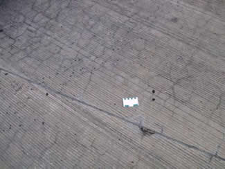
Figure 35. Cracking of 11-Year-Old Untreated Section of S.R. Rt. 1 in Delaware.
Figure 35 shows the nature of the cracking observed on one of the untreated sections during an examination in the summer of 2001. The untreated section at the southern end of the project has undergone accelerated deterioration in the past few years, especially in the vicinity of the control joints. Consequently, frequent patch and partial-depth repairs of joints have been required on this section. The two treated sections and the second control section have required fewer repairs.
Figure 36 shows 2 photographs to compare the visual appearance of the treated and untreated sections located at the southern end of the project. The photographer stood at the point where the two sections meet. The picture to the left is the view north showing the treated concrete, and the picture to the right is the view south showing the untreated concrete. The difference between the two sections is quite apparent. The difference between the two sections is quite apparent. It is interesting to note that despite the differences in visual appearance in the treated and untreated concrete, the physical testing (modulus and impact echo) has detected little difference in the behavior of the concrete has been detected by the physical testing (modulus and impact echo).
The untreated section of the southern end of the project is scheduled for rehabilitation, which will probably take the form of removing the deteriorated surface by milling and resurfacing with an asphalt overlay. The Delaware DOT views the lithium treatment as successful in terms of extending the life of the pavement (Pappas, 2001), becauseas repairs of the treated sections do not require resurfacing at this time.
|
|
a) Treated Concrete b) Untreated Concrete |
Summary and Other Projects
A summary of the above projects and two others is presented in table 16. The two other projects listed are concrete pavements in New Ulm, MN, and High Point, NC. Both of these pavements were in a fairly advanced stage of deterioration when they were treated and it has not been possible to discern any benefits due to lithium treatment. In fact, the pavement rehabilitation of the pavement in North Carolina included an asphalt overlay following treatment with lithium that was applied to stabilize the underlying concrete. Two more pavement rehabilitation projects using a combined lithium treatment and asphalt overlay are planned in the state of Delaware this year. Similarly, a lithium treatment under a methacrylate wearing surface is being placed on a bridge deck in Reno, Nevada.
Other projects involving topical applications of lithium have included pavements in Lexington and Selby, NC, Albuquerque, NM, Cheyenne, WY, and Dover, DE.
Date of 1st Application |
Structure Type |
Location |
Application Rate (L/100 m2) |
No. of Appl. |
Condition Prior to Treatment |
Comments on Effectiveness |
|---|---|---|---|---|---|---|
1995 |
Pavement |
U.S. Rt. 14, Wolsey, SD |
18.36, |
1 |
Fair |
Little visible difference (controls and treated areas unchanged during evaluation period) |
1997 |
Bridge deck |
U.S. I-68, LaVale, MD |
36.72 |
1 |
Good |
Little visible difference (controls and treated areas unchanged during evaluation period) |
| 1998 | Pavement and bridge decks |
S.R. Rt. 1, Bear, DE |
24.48 |
6 (2/yr for 3 yrs) |
Good to fair |
On southern end of project, treated areas faring better than control-no noticeable difference on northern end |
| 1998 | Pavement |
S.R. 15, New Ulm, MN |
24.48 |
1) |
Fair to poor |
No noticeable improvement (controls and treated areas both continued to deteriorate about the same) |
1999 |
Pavement |
U.S. I-85, High Point, NC |
12.24 |
1 |
Fair |
Not evaluated -used as enhancement of durability of asphalt overlay |
4.3.2 Electrochemical Migration
Bridge Abutments, Latchford, Ontario (1992)
This arch bridge carries Highway 11 over the Montreal River just south of Latchford, in Northern OntarioON (figure 37). Electrochemical chloride extraction (ECE) was used to treat corrosion problems in the abutments, because concrete removal was not an option in the vicinity of the bearing seat of the steel arch. Lithium borate was used as the electrolyte in the ECE system to reduce the risk of exacerbating ASR, as the structure was thought to contain potentially reactive aggregates. The process of ECE results in the generation of hydroxyl ions OH- at the embedded steel cathode, thus increasing the risk of ASR. Further augmentation of the alkalies may occur, as sodium borate is often used as the electrolyte. The use of a lithium-based anolyte should offset the effects of the increased pH.
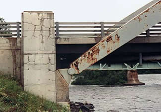
Figure 37. Bridge over Montreal River near Latchford, ON Ontario.
This case has been discussed in detail elsewhere (Manning and Ip, 1994). Continued monitoring of the structure to determine the effectiveness of the treatment was planned, but it is not known if any such monitoring is taking place.
Bridge Deck, Arlington, VA (1995)
As with the bridge in Ontario described above, the main purpose of the electrochemical treatment of the bridge deck on U.S. I-395 in Arlington was to he remove al of chlorides, and lithium borate was used as the electrolyte in response to concerns regarding the potential for ASR. Details of the project are given elsewhere (Whitmore and Abbott, 2000). The installation and operation of the system was typical of any other ECE application, with the exception that special measures were required to prevent electrolyte run-off of the electrolyte from the sloping deck. The treatment lasted for 8 eight weeks, and periodic analysis of the electrolyte during this period indicated a rapid decrease in the lithium concentration over time. Cores taken before and after treatment showed that the lithium penetrated a significant distance into the concrete. Lithium concentrations at a depth of 6 to 19 mm ranged from 315 to 343 parts per million (ppm), and at a depth of 19 to 32 mm the concentrations of lithium were in the range 203 to 265 ppm.
Bridge Deck, Seaford, DE (1997)
ECE treatment with lithium borate as an electrolyte was also applied on a 50-year-old bridge, classified as a heritage structure in Seaford, DE.
Pier Footings, New Jersey Turnpike, NJ (1999)
The remediation of five pier footings on the New Jersey Turnpike was likely the first time an electrochemical migration technique was used solely for the purpose of reducing the potential for ASR (Whitmore and Abbot, 2000). Figure 38 shows a photograph of the system during operation.
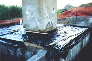
Figure 38. Application of an Electrochemical Lithium Migration Technique
for a Pier Footing on the New Jersey Turnpike.
Repair of some of the larger cracks was carried out prior to lithium treatment and in such cases the mix water for the grout was a 10 percent LiNO3 solution. The footings were massive sections (approx. 6 m by 6 m by 1.5 m deep), with a single mat of steel at a depth of approximately 1 m. The small amount of steel necessitated required the use of a system of embedded anodes and cathodes. A series of vertical holes were drilled to a depth of just less than 1 m into the footing. Into some of these holes, steel cathodes were grouted in place and connected together with the reinforcing mat to the negative terminal of the rectifier. A titanium anode was inserted into other holes, and these were connected to a titanium mesh covering the top surface of the footing. The anodes were connected to the positive terminal of the rectifier. A lithium borate solution was used as an anolyte to fill the holes containing anodes and to pond the top surface of the footing.
4.3.3 Pressure Injection
Pressure injection techniques frequently are used to help grout materials assist the penetrate ion of grout materials into concrete. Such techniques generally are not recommended for concrete damaged by ASR, as the internal pressures may lead to disruption of the concrete.
4.3.4 Vacuum Impregnation
Vacuum impregnation is an alternative to pressure injection and has been used for increased grout penetration into cracked concrete. This technique should lend itself to applications where lithium impregnation is desired. There are no known cases involving the vacuum impregnation of lithium into concrete, however, at least three trials were scheduled for the summer of 2002.