U.S. Department of Transportation
Federal Highway Administration
1200 New Jersey Avenue, SE
Washington, DC 20590
202-366-4000
Federal Highway Administration Research and Technology
Coordinating, Developing, and Delivering Highway Transportation Innovations
 |
| This report is an archived publication and may contain dated technical, contact, and link information |
|
Federal Highway Administration > Publications > Research > Structures > Electrochemical Chloride Extraction: Influence of Concrete Surface on Treatment |
Publication Number: FHWA-RD-02-107 |
Previous | Table of Contents | Next
One of the most critical gaps in the management of highway safety is the lack of a reliable method for estimating the safety performance of an existing or planned roadway. Accident record systems have been developed and maintained by highway agencies to monitor the safety performance of their roadways, but these provide historical or retrospective data. Effective management requires a prospective viewpoint. Highway engineers need to know not what the safety performance of a roadway was in the recent or distant past, but what it is now and what it is likely to be in the future if particular proposed actions are taken.
This report contains typical scientific abbreviations.
It is known that chlorides can lead to corrosion in reinforced concrete structures. A second detrimental factor then transpires because the corrosion product requires a larger volume of space than the original iron. This creates tensile stresses, which makes the concrete more prone to cracking and spalling. If this process continues, premature deterioration of a bridge can result. Therefore, in chloride contaminated bridges it is vital to have a method for alleviating the corrosive attack on the reinforcing steel. Currently, two electrochemical methods are available, cathodic protection (CP) and electrochemical chloride extraction (ECE), each having certain advantages and disadvantages. Although ECE is a proven means of removing chlorides from the concrete while increasing the pH in the region adjacent to the reinforcing steel, extensive use has not developed partially due to a deficient understanding in the following issues:
Interest in the movement of ions through concrete has prompted numerous studies, both theoretical and experimental. Currently, data from field and laboratory experiments indicate certain regions in concrete appear to lead to inefficient chloride extraction. By determining the regions of low efficiency and the controlling mechanisms, questions relating to extraction rates, efficiency, and beneficial life can be addressed. It is anticipated that upon the completion of this project, techniques for altering the procedure and/or materials will provide a means to improve the ECE process.
Despite differing opinions on corrosion mechanisms and ion ingress into concrete, the concentration and movement of oxygen, chloride, and hydroxyl ions are all considered important factors in the corrosion of reinforcing steel. However, chloride ions are considered the key factor with regard to the corrosion. Li, et al., presented the flow chart shown in figure 1, which is based on the work from several studies that investigated the relationship between chloride concentration and reinforcing steel corrosion.[1] This diagram emphasizes the numerous factors that could influence the corrosion threshold value.[1]
Early research into the corrosion of reinforcing steel indicated that a change in alkalinity near the reinforcement can significantly influence the steels' susceptibility to corrosive attack.[2] According to Hausmann, the chloride threshold value, which is given in equation 1, is a function of the chloride and hydroxyl ion concentrations ratio and should not exceed 0.61.[2]
 |
(1) |
Figure 1. Potential influences on the corrosion threshold for steels exposed to chlorides [1]
Based on the relationship in equation 1, it has been suggested that concrete could have a higher percentage of chlorides if they were introduced during the mixing stage, due to binding of some of the chloride, versus if chlorides diffuse into a cured concrete block.[3, 4] Other researchers have produced estimates for the chloride threshold value that range from 75 - 3640 ppm in concrete.[5] The effects of several other factors on the corrosion threshold value are summarized in Table 1.
Table 1. Factors influencing corrosion threshold value[3, 5-12]
| Description | Effect on Threshold Value |
|---|---|
Dehydration of concrete | Increases |
Water saturation resulting in oxygen depletion | Increases |
Concrete sealed or pores constricted | Increases |
Increase in humidity | Decreases |
Changing concrete mixture (i.e. admixtures, w/c ratio) | Increases or Decreases |
The concept of removing chloride ions from concrete by electrochemical migration was borne in 1973 out of Kansas Department of Transportation (KDOT) experiments on electro-stabilization of clayey soils. [13] Since then, numerous studies have shown it is possible to remove chlorides from concrete using electrochemical means.[14-17] To facilitate the treatment of vertical surfaces a commercial electrochemical method was developed, which is known as NorcureTM.[18] The benefit of removing the chloride ions electrochemically is that contaminated concrete that are still structurally sound would not require excavation and will remain in place after the application of the chloride removal process. This restoration technique has inherited various names; electrochemical chloride removal, desalination, and electrochemical chloride extraction.
ECE and CP have some distinct similarities and differences. Although both are DC techniques that cathodically polarize the reinforcing steel and reduce the corrosion rate, CP is usually permanently installed, operates at lower current densities (approximately 10 mA/m2), and usually requires routine maintenance.[17] Figure 2 is an illustration of a typical CP system installed on a bridge deck with the anode permanently embedded in the concrete overlay. In contrast, ECE is an in-situ restoration technique that is designed to remove chlorides and increase the alkalinity adjacent to the reinforcing steel. A temporary treatment system is attached to the concrete and the applied voltage causes a direct current, which can be up to 1 A/m2, to flow through the concrete for typically 4 to 8 weeks.[14, 16, 17] The ECE system is then removed following completion of the treatment process. Currently, ECE of bridge decks, using a system such as that illustrated in figure 3, requires changes to the traffic pattern during operation. However, ECE of concrete bridge piers do not generally require the rerouting of traffic.
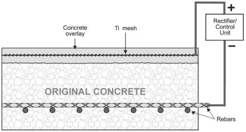
Figure 2. Cathodic protection system for reinforced concrete
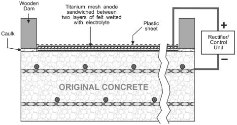
Figure 3. Illustration of ECE setup on the 34th Street Bridge in Arlington, Virginia, USA [17]
Both electrochemical techniques produce hydroxyl ions at the cathode or the rebars, while water is decomposed at the anode.[16] As shown in the following reactions, hydrogen gas can be produced at the cathode, and chlorine evolution and/or acidification of the electrolyte can occur at the anode during ECE. Two possible reactions at the cathode during ECE are: [16]
| 2H2O + O2 + 4e- -> 4OH- | (2) |
| H2O + e- -> HoADS + OH- | (3) |
At the anode, ECE can generate the following reactions: [16]
| 2H2O -> 4e- + O2 + 4H+ | (4) |
| 2Cl- -> 2e- + Cl2 | (5) |
In addition, the following chemical reaction can occur in the electrolyte: [16]
| H2O + Cl2 -> HCl + HClO | (6) |
As hydroxyl ions are produced at the cathode the pH adjacent to the steel increases, which is beneficial for the rebar, but these electrochemical reactions can create adverse effects like hydrogen embrittlement or alkali aggregate reaction. In equation 3, "HoADS" is nascent hydrogen, which could either enter the metal or form hydrogen gas. These issues are discussed further in the section "Effects of Electrochemical Chloride Extraction" on page nine.
Figure 3 is an illustration of an ECE system using a catalyzed titanium mesh anode, however other anodes have performed satisfactorily.[14, 16, 17, 19-25] Steel mesh anodes cost less than inert catalyzed titanium mesh anode, but some of the steel is consumed during the extraction process and therefore it has a shorter functional life.[20, 26] In addition, some have suggested that the corrosion product from the steel anode can deposit in concrete pores and decrease the chloride extraction efficiency if ECE is being applied on an upward facing horizontal surface.[25]
Potable water has shown favorable results as an electrolyte during ECE.[22] Calcium hydroxide solutions have also been used as an electrolyte in many applications. A benefit of using calcium hydroxide is it reduces the chance of the electrolyte becoming acidic and etching the concrete when a catalyzed titanium anode is used.[17, 26] In addition, increasing the alkalinity of the electrolyte reduces the evolution of chlorine gas.[25] A third common electrolyte is lithium borate solution, which is useful when dealing with concrete containing aggregates susceptible to alkali-aggregate or alkali-silica reaction (ASR).[22, 26, 27] The lithium borate solution is actually a mixture of lithium hydroxide and boric acid, which ensures lithium ions are available to penetrate the concrete and reduce or eliminate ASR.[3, 26] This solution is the most expensive of the commonly used electrolytes.[26] Although the electrolytes presently used for ECE do not contain corrosion inhibitors, Asaro, et al., demonstrated in a strategic highway research program (SHRP) study that it is possible to inject inhibitors using a similar setup as ECE.[28]
During ECE it is important to maintain good contact between the electrolyte and the concrete surface to minimize circuit resistance. This has been accomplished using three different methods: sprayed cellulose fiber, synthetic felt mats, and surface-mounted tanks.[22, 26] For vertical surfaces, sprayed cellulose fiber and surface-mounted tanks are generally used.[20, 22, 26] When treating horizontal surfaces, synthetic felt mats are more common.[22, 26]
Work by Christensen, et al., suggested that the binding of ionic species and the increase in alkalinity during the hydration process has a strong influence on the conductivity.[29] During the early stages of hydration in a chloride free cement (£100hr.), conductivity is dominated by Na+, K+, Ca2+, OH-, and SO4-2.[29] As the hydration process continues, Christensen, et al., found that only Na+, K+, and OH- contribute significantly to the conductivity in these samples.[29] With equation 7 and using the ionic conductivity values given in table 2, Banfill calculated the transference values for a mixture containing 0.5 mol/liter sodium hydroxide and 0.5 mol/liter sodium chloride, which are given in table 3.[30] Based on these values, it was concluded that the current flow from the reinforcing steel toward the anode was composed of 72% hydroxyl ions and 28% chloride ions during electromigration.[30]
 |
(7) |
Where,
tj | = | Transference number of species j | λ | = | Ionic conductivity of j (infinite dilution) | |
|
Ij |
= |
Current due to species j |
F |
= |
Faraday constant | |
|
Itotal |
= |
Total current |
Wj |
= |
Mass of species j removed | |
|
zj |
= |
Charge on species j |
t |
= |
Time | |
|
cj |
= |
Concentration of species j |
Table 2. Ionic conductivity values [30]
|
Positive |
Conductivity |
Negative |
Conductivity |
|---|---|---|---|
|
H+ |
349 |
OH- |
198 |
|
Na+ |
50.1 |
Cl- |
75.2 |
|
K+ |
73.5 |
½ SO42- |
79.8 |
|
Ca2+ |
59.5 |
½ CO32- |
69.3 |
HCO3- |
44.5 |
Table 3. Calculated transference values for
a solution
containing 0.5 mol/l NaCl and 0.5 mol/l NaOH [30]
Species |
Value |
|---|---|
|
tNa+ |
0.27 |
|
tOH- |
0.53 |
|
tCl- |
0.20 |
The calculation by Banfill assumed that for every 96,500 coulombs of charge passed, one mole or 35.5 g of chloride ions successfully migrated to the anode.[30] However, after calculating the efficiency of an early SHRP study (6.9-7.8%), Banfill concluded that other negative ions (i.e. OH-, SO4-2) and resistive heat generation must account for the efficiency loss.[30, 31] Tritthart demonstrated that the concentration of hydroxyl ions in concrete increased during ECE, and suggested that during ECE the hydroxyl ion influences the rate of removal of the chloride ion.[32] This is because as hydroxyl ions are being produced at the cathode and migrating towards the anode during ECE, these ions will compete with chloride ions as charge carriers. Therefore, based on the calculations by Banfill and the results from Tritthart, it is not surprising that the efficiency of chloride removal would decrease as the treatment progressed.[30, 32]
Chatterji suggested that although free chloride ions can participate in electrolysis, bound chloride ions would first require exchange with hydroxyl ions before being able to contribute to the conductivity.[15] For the exchange between bound chloride ions and hydroxyl ions to occur, Chatterji proposed that the electrolysis would require sufficient time and an elevated hydroxyl ion concentration.[15] The fact that not all of the chlorides are initially free to migrate could reduce the extraction efficiency of the process.[33] In the work by Elsener, et al., indications of a chemical equilibrium between bound and free chlorides were shown.[19] Others have supported this idea and have even included this as a factor in proposed models.[34-36] Ihekwaba, et al., suggested the following chemical equation would exist for a chloroaluminate compound, [37]
| CaCl2 + 3CaO·Al2O3 + 10H2O ↔ 3CaO·CaCl2·Al2O3·10H2O | (8) |
All these studies have led to the development of some general relationships between the various factors and ECE. Table 4 summarizes these relationships, which were determined either experimentally or through modeling. However, cracks in the concrete are not addressed in this table. This is because it was determined that the effect of small cracks (½0.5 mm wide) did not significantly affect the current distribution.[31] Bennett, et al., suggested that even though small cracks appeared to fill with a white precipitate during ECE, it is best if damaged concrete is repaired prior to ECE.[31] In addition, Bennett, et al., indicated that variations in the depth of cover did not greatly influence the current distribution during ECE.[31]
Table 4. Influences of various factors on ECE [31, 37-41]
| Factor | Effect |
|---|---|
|
Increase quantity of reinforcing steel |
Increases chloride extraction rate |
|
Increase the applied voltage |
Increases chloride extraction rate |
|
Higher initial chloride concentrations |
Increases chloride extraction rate |
|
Reinforcement mats placed directly over each other ** |
Increases chloride extraction rate |
|
Increasing temperature above 35oC |
Increases chloride extraction rate |
|
Multiple applications of ECE |
Increases chloride extraction efficiency |
|
Initial chloride concentration on final chloride concentration |
No influence |
|
Potentiostatic vs. galvanostatic operation |
No influence |
|
Renewal of anolyte to maintain maximum concentration gradient |
No influence |
|
Carbonated layer in front of chlorides being extracted |
Decreases chloride extraction rate |
|
** Based on mathematical model |
Electrochemical Chloride Extraction Projects
Various studies have demonstrated ECE is a promising bridge restoration alternative to CP for chloride-contaminated concrete bridges.[8, 14, 16, 17, 20-23, 26, 42, 43] Table 5 lists the reinforced concrete structures in North America that were treated using ECE. The majority of these structures can be categorized as either bridge piers or decks. In addition, this table includes a summary of the percentage of chlorides removed from selected North American structures using ECE treatment. Unfortunately, many of these results are not reported for the same concrete depths, so a comparison between structures is impossible. However, it is clear that although the amount of chlorides removed from most of these structures was substantial, some of the chlorides remain in the structure following treatment. [3, 19]
Half-cell measurements on some of these treated structures following ECE treatment indicate a low probability of corrosion. Table 6 lists the half-cell measurements that were taken on treated and untreated structures. In addition, all of the structures listed in table 6 are also cited in table 5.
Table 5. ECE treatment on selected North American structures [17, 21, 31, 42-55]
| Location | Date | Area Treated |
Chloride Removed (%) |
Current Efficiency (%) |
|---|---|---|---|---|
Hwy #192 Bridge Substructure, Council Bluffs, Iowa |
2000 |
1209 m2 |
N/A |
N/A |
Highway 11 Bridge Abutments, North Bay, Ontario |
2000 |
646 m2 |
N/A |
N/A |
Eastern Avenue Bridge #576 Abutments, Washington DC |
2000 |
220 m2 |
N/A |
N/A |
3rd St. Viaduct, Bridge Substructure, Minot, North Dakota |
1999 |
100 m2 |
N/A |
N/A |
St. Adolphe Bridge Deck, St. Adolphe, Manitoba |
1999 |
14704 m2 |
N/A |
N/A |
S02 of 38061 Substructure, Jackson County, Michigan |
1999 |
109 m2 |
N/A |
N/A |
I-480 Bridge Substructure, Omaha, Nebraska |
1999 |
1400 m2 |
N/A |
N/A |
Burlington Skyway Substructure, Burlington, Ontario |
1999 |
1533 m2 |
N/A |
N/A |
Hwy #192 Bridge Substructure, Council Bluffs, Iowa |
1998 |
463 m2 |
N/A |
N/A |
I-480 Bridge Substructure, Omaha, Nebraska |
1998 |
1525 m2 |
74 (at 0-25 mm) |
N/A |
St. Adolphe Bridge Deck, St. Adolphe, Manitoba |
1998 |
1115 m2 |
84 (at 0-25 mm) |
N/A |
Pembina Highway Overpass Structure, Winnipeg, Manitoba |
1998 |
220 m2 |
N/A |
N/A |
Industrial Spur Bridge Substructure, Peoria, Illinois |
1998 |
462 m2 |
N/A |
N/A |
Starbuck Bridge Deck, Winnipeg, Manitoba |
1997 |
270 m2 |
N/A |
N/A |
I-395 & Dunwoody Substructure, Minneapolis, Minnesota |
1997 |
225 m2 |
N/A |
N/A |
Carousel Center Parking Deck, Syracuse, New York |
1997 |
100 m2 |
N/A |
N/A |
Islington Ave. Bridge Interceptor Chambers, Toronto, Ontario |
1997 |
180 m2 |
N/A |
N/A |
Burlington Skyway Substructure, Burlington, Ontario |
1997 |
268 m2 |
N/A |
N/A |
Tulls Highway Overpass Deck, Seaford, Delaware |
1997 |
1550 m2 |
N/A |
N/A |
Hwy #6 & #11 Overpass Piers, Regina, Saskatchewan |
1995 |
180 m2 |
Up to 80 |
N/A |
5th Street & I-64 Substructure, Charlottesville, Virginia |
1995 |
488 m2 |
27-60 (at 6-19 mm) |
9 to 12 |
Hwy #1 & #6 Overpass Piers, Regina, Saskatchewan |
1995 |
370 m2 |
N/A |
N/A |
Hwy #2 Overpass Piers, Morinville, Alberta |
1995 |
55 m2 |
62 -96 |
N/A |
34th Street & I-395 Bridge Deck, Arlington, Virginia |
1995 |
733 m2 |
76-82 (at 6-19 mm) |
11 to 15 |
Hwy #11 & #16 Overpass Piers, Saskatoon, Saskatchewan |
1994 |
150 m2 |
62-88 |
N/A |
Pier Columns, SHRP, USA |
1992 |
49 m2 |
N/A |
7 to 13 |
Abutment Area, SHRP, USA |
1992 |
17 m2 |
N/A |
12 to 19 |
Deck Area, SHRP, USA |
1991 |
136 m2 |
60 (25 mm from bars) |
20 |
Portage Avenue & Rt. 90 Retaining Wall, Winnipeg, Manitoba |
1991 |
N/A |
20 - 76 |
N/A |
Burlington Skyway Pier, Burlington, Ontario |
1989 |
31 m2 |
27 (East Face) |
11 (East) 32-33 (West) 30 (South) |
U.S. Route No. 33 Bridge Deck (ODOT No. UNI-33.1138-R) |
1975 |
18 m2 |
31 in 12 hr (at 0-25 mm) |
N/A |
N/A = Not Available |
Table 6. Half-cell potentials on treated and untreated North American structures [43, 44, 49]
| ECE Date | Location | Test Date | Half Cell, mV (vs. Cu/CuSO4) |
|---|---|---|---|
| 1989 | Burlington Skyway Pier, Burlington, Ontario |
Untreated |
0% > -200 |
96% between -200 and -350 | |||
4% < -350 | |||
Treated |
96% > -200 | ||
4% between -200 and -350 | |||
0% < -350 | |||
| 1991 | Portage Avenue & Rt. 90 Underpass Retaining Wall, Winnipeg, Manitoba | Untreated |
84% < -350 |
Treated |
100% > -280 | ||
| 1995 | Hwy #6 & #11 Overpass Piers, Regina, Saskatchewan |
Untreated |
49% > -200 |
27% between -200 and -350 | |||
24% < -350 | |||
Treated |
99% > -200 | ||
1% between -200 and -350 | |||
0% < -350 | |||
| 1997 | Starbuck Bridge Deck, Traffic Bearing System, Winnipeg, Manitoba |
Untreated |
6% > -200 |
75% between -200 and -350 | |||
19% < -350 | |||
Treated |
96% > -200 | ||
4% between -200 and -350 | |||
0% < -350 |
The beneficial effect of ECE on the reduction of corrosion induced concrete deterioration of a structure after the treatment is important. However, there were concerns about the structural effects of ECE, such as hydrogen evolution at the cathode, bond strength loss between the concrete and reinforcement, and ASR susceptibility around the reinforcement. Many of these issues relate to the high voltage and current densities used during extraction, which changes the chemistry around the reinforcement and redistributes ionic species, thus altering the concrete's properties.[3, 56, 57]
The generation of nascent hydrogen at the cathode is inevitable due to the high voltages used during ECE.[3, 24] If hydrogen is absorbed into the steel, it could lead to hydrogen embrittlement and reduce the fracture toughness of the steel.[15, 24] If hydrogen gas is produced, it can increase the local pressure and eventually promote cracking.[15, 24, 57] Currently, research indicates that hydrogen evolution will not adversely affect the structure, if current density levels are kept at 1 A/m2 or less.[3, 23, 25] In addition, the lower strength steels used for reinforcement are not as susceptible to hydrogen embrittlement as high-strength steel.[3, 23] It is not surprising then that ECE is currently not recommended for high-strength steels used in prestressed concrete.[3, 23]
A study by Bennett, et al., suggested that porosity increased in the cement paste adjacent to the reinforcing steel.[31] Using mercury porosimetry, it was determined that a significant increase occurred in the one- to ten-micron pore range following ECE.[31] In addition, the cement adjacent to the top steel mat had undergone softening when compared with concrete extracted from deeper depths.[31] Ihekwaba, et al., noted the softening effect when the concrete was exposed to higher current densities (3 A/m2), but the effect was insignificant in samples exposed to lower current densities (1 A/m2).[60] However, Bertolini, et al., did not observed a statistically significant change in microhardness measurements made near the reinforcing steel after exposing samples for twelve weeks to current densities that ranged from 5 mA/m2 to 5 A/m2.[58] In addition, Bennett, et al., indicated that even at high current densities (20 A/m2), ECE was not detrimental to the compressive strength of the concrete.[31]
Broomfield discusses research that indicates that corrosion product on the surface of the reinforcing steel improves the bond strength with the concrete.[3, 25] The elimination of expansive corrosion product during ECE seems to reduce this bond strength.[3] Initially, the force required is greater for the corroded sample, but as the ECE treatment time increases, the pull out load decreases to approximately the same value as the control sample.[3] Others have shown that in addition to removing chlorides, ECE physically changes the concrete.[61, 62] However, these effects appear to be minor at the current densities commonly employed during the ECE process.
Bertolini, et al., indicated that ASR could result if ECE was applied to concrete containing susceptible aggregate.[58] This was due to accumulation of alkali metal ions and hydroxyl ions near the reinforcing steel during ECE.[3, 23, 58] However, electrolytes containing lithium ions (i.e. lithium borate electrolyte) have demonstrated the ability to suppress ASR.[3, 23, 59]
Currently, the primary focus of the research has been to study how the electrical parameters of the regions between the anode and the cathode change during ECE. It was expected that this approach would provide insight into the decrease in current flow during the early stage of ECE treatment, with which improvements to the efficiency of chloride removal can be made. In addition, the influence of w/c ratio on ECE was investigated using specimens made of several w/c ratios. It was hoped that this might lead to a correlation between the w/c ratio and the time required for chloride extraction.

