U.S. Department of Transportation
Federal Highway Administration
1200 New Jersey Avenue, SE
Washington, DC 20590
202-366-4000
Federal Highway Administration Research and Technology
Coordinating, Developing, and Delivering Highway Transportation Innovations
 |
| This report is an archived publication and may contain dated technical, contact, and link information |
|
Publication Number: FHWA-HRT-06-078
Date: June 2006 |
|||||||||||||||||||||||||
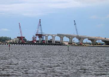
Job Site Evaluation of Corrosion Resistant AlloysAPPENDIX C FHWA Project NUMBER FL-00-01, part 2TEA-21 INNOVATIVE BRIDGE CONSTRUCTION PROGRAM State: Florida. State DOT Contact: Mr. Randall Scott, P.E. [(772) 225-1888]. Bridge Number: 890145 (Frank A. Wacha Bridge). Project Type: Replacement. Location: Bridge crossing the St. Lucie River at Jensen Beach, FL. Innovative Material: Type 2201 Stainless Steel Reinforcement. Bridge Description: The bridge is the center of three two-lane structures5 that serve as a causeway between Jensen Beach and South Hutchinson Island on the southeast Florida coast. It is replacing a 50-year-old, low-profile, two-lane bascule bridge that has become badly deteriorated because of the combined effects of brackish water exposure and age, and is now functionally obsolete. Figure 18 shows a perspective photograph of the project which is scheduled for completion in March 2005 (note the old bridge in the background). The substructure design involves conventional, driven prestressed piles, cast-in-place footers, columns and cast-in-place hammerhead column caps. The superstructure is constructed with precast Florida bulb-tee beams and a cast-in-place deck. Unlike northern areas that employ deicing salts such that deterioration from embedded steel corrosion and concrete cracking and spalling is largely confined to the deck, it is the substructure of coastal bridges in Florida that typically experiences the greatest distress. While most of the reinforcement in this bridge is conventional bar or prestressing strand, the footer and column of two piers (numbers 11 and 12, which are just to the right of the leftmost crane in figure 18) are being constructed using Type 2201 stainless steel. The eastern bridge, the construction of which is of longer duration, will have MMFX-II reinforcement in eight deck spans.
Figure 18. Perspective photograph of the Jensen Beach Causeway Bridge under construction. Innovation Justification: The bridge is subject to a marine exposure in a semitropical south Florida coastal environment. It is anticipated that 2201 stainless steel (ss) reinforcement will provide improved confidence that structures of this type can achieve a 100-year life. Construction Sequence: The contractor’s construction sequence involved the following sequential steps:
Figure 19. Photograph of driven, cut-off prestressed piles for pier 11.
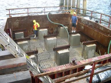
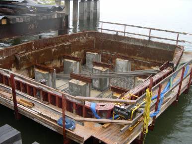
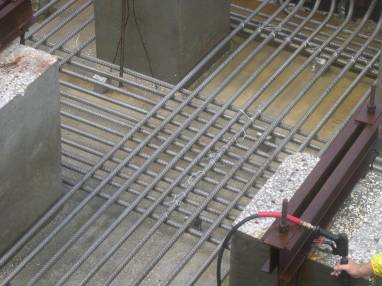
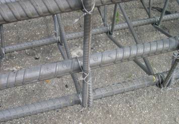
Figure 22 shows a closer view of the in-place 2201 bars at the bottom of the footer for pier number 12. The threaded conventional steel bars and support I-beams upon the piles remain in place, but the black bars will be isolated from the 2201 prior to concrete pouring. The tie wire is also stainless steel (type unknown).
Figure 22. View of 2201 ss in place at the base of the footer formwork. Figure 23 shows a perspective view of the reinforcement cage for column number 11 as fabricated prior to placement. At the time of this photograph, the cage had been in this position for approximately six weeks. Figure 24 is a closeup view of a portion of the cage showing the bars to be generally excellent condition. Figure 25 shows a conventional bar reinforcing steel cage for a hammerhead column cap that had been exposed for approximately the same length of time as the column cage (figures 23 and 24). Here, rusting over the whole surface is apparent.
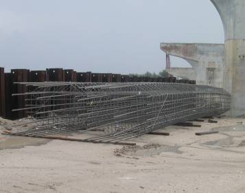
Figure 23. Photograph of 2201 ss reinforcement cage for the column of pier number 11.
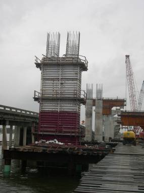
Figure 25. Photograph of the conventional bar reinforcement cage for a hammerhead column cap. Figure 26 shows a photograph that was taken several weeks after the ones above of the column steel and forms of pier number 11 in place.
Figure 26. Photograph of pier number 11 column formwork and 2201 ss cage in place. Reinforcement Specification: The column and bottom mat footer bars are #36 (metric designation) and the top mat footer bars are #19 (metric designation). A total of 8,048 kg (17,746 lb) of reinforcement was required for each footer. The column of pier number 11 required 10,422 kg (22,981 lb) of reinforcement and for pier number 12, 9,741 kg (21,479 lb), with the difference resulting from the difference in height. Clear cover in both cases is specified as 115 mm (4.5 inches). Concrete Specification: The concrete was specified as conforming to class IV of section 346 of the FDOT State Specifications Office. Table 8 provides a listed of required properties.
MPa = megapascal; 1 MPa = 20.885 ksi Job Contractor: Archer Western, Inc. Jacksonville, FL Steel Supplier: Gerdau Ameristeel, Inc., as supplied by Avesta Sheffield in Sweden. Material Cost: The delivered cost was $2.43/kg ($1.10/lb). Job Site Storage: The column cage fabrication commenced shortly after bars were delivered. Consequently, the bars were stored elevated but uncovered per FDOT Specification 415. Special Considerations: Prior to delivery of the steel, the supplier (Gerdau Ameristeel, Inc.) expressed concern that the as-rolled 2201 would develop surface rust as a consequence of the use of carbon steel rolling and handling equipment. A test program was performed by the FDOT Corrosion Laboratory in Gainesville, FL, to assist in selection of an appropriate surface treatment. A copy of the report issued by FDOT is attached as appendix C1. Based upon this, blasting with silica sand was selected with the specification for this, as is described in appendix C2. From the appearance of the stainless steel at the job site (see figures 20–24), this treatment accomplished what was intended. During construction, ground leads were installed to the 2201 column steel. The purpose of these was to facilitate subsequent continuity and corrosion test measurements. The work was performed by Concorr Florida, Inc., under direction from the FDOT Corrosion Laboratory in Gainesville, FL. Construction Difficulties: The 2201 column and footer cages were fabricated on the construction site. Because the source of replacement reinforcement was in Sweden, possible delay resulting from mistakes raised concerns. However, the fabrication occurred without incident; and so this concern did not materialize. Florida Department of Transportation Corrosion Research LaboratoryFour sets of 16-mm bars of alloy 2201 stainless steel furnished by Gerdau Ameristeel, Inc., were received for testing per ASTM G85, “Standard Practice for Modified Salt Spray (Fog) Testing.” The four sets received had different surface condition per table 9: Table 9. Listing of reinforcements and surface condition for each.
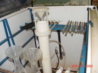
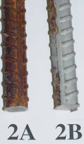
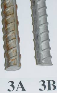
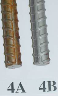
Half of the bars for each set were pickled per ASTM A380, “Standard Practice for Cleaning, Descaling, and Passivation of Stainless Steel Parts, Equipment, and Systems,” Table A1.1 “Acid Descaling (Pickling) of Stainless Steel,” Code B, followed by scrubbing with plastic fiber brush in hot running tap water. The bars were exposed in salt spray tank for 3 days positioned horizontally as shown in figure 27.
Figure 27. Bars positioned in salt fog chamber. The photographs in figures 28–31 show the condition of the bar samples after salt spray exposure.
Type 2201 Stainless Steel surface preparation procedureJacksonville Mill 217 Yellow Water Road Jacksonville, FL 32234 Stainless Blasting ProcedureWork to be performed at Blast Tech.
5 It was originally planned that span 4 would utilize stainless clad bars from a second source; however, these could not be delivered according to the construction schedule.
|
|||||||||||||||||||||||||