U.S. Department of Transportation
Federal Highway Administration
1200 New Jersey Avenue, SE
Washington, DC 20590
202-366-4000
Federal Highway Administration Research and Technology
Coordinating, Developing, and Delivering Highway Transportation Innovations
| REPORT |
| This report is an archived publication and may contain dated technical, contact, and link information |
|
| Publication Number: FHWA-HRT-13-026 Date: March 2014 |
Publication Number: FHWA-HRT-13-026 Date: March 2014 |
The primary purpose of building models is to evaluate alternatives in support of the decisionmaking process. The alternatives analysis process has two fundamental parts: the simulation modeling of alternatives and the sequencing of the alternatives to analyze. From an overall workflow perspective, the alternatives analysis step is similar for all projects in terms of how the modeling steps are conducted. However, the number of alternatives and workflow for what is being analyzed and reported can be very different and therefore needs to be customized based on the issues and the nature of the proposed project and improvements.
There are three main areas of consideration for an alternatives analysis, as shown in figure 21. There is the simulation modeling work itself, which includes carrying forward relevant calibration parameters, satisfying the required number of model runs, forecasting traffic, and ensuring that error checking has been conducted. The second area is the sequencing of alternatives and timeframes that are to be simulated. Time should be invested up front to investigate and lay out an optimal approach for the sequencing of the simulation analysis to reduce the overall level of effort. The third area is the presentation of modeled results, where the report summaries must be designed to be illustrative and effective at communicating differences.

Figure 21. Flowchart. Alternatives analysis workflow.
Key considerations for the alternative analysis step include the following:
In some occasions, the simulation analysis may not be sensitive enough to distinguish between subtle nuances between similar alternatives. For example, simulation models cannot really distinguish between operational characteristics of two alternatives featuring a difference of 20 ft in the length of a storage lane. Similarly, simulation tools may not adequately analyze the differences between other design features such as shoulder widths, lane widths, and taper rates of acceleration and deceleration lanes. It is important that parameters are identified upfront about the realistic capabilities of what the simulation can and cannot be used to evaluate.
The requirements for an alternatives analysis depend on the type of project. The focus of this report is interstate freeway improvement projects. The level-of-effort case studies presented in chapter 1 include two projects requiring FHWA approval for interstate access requests. One project was a national highway system freeway (TH 100) that does not require the same FHWA approval as an interstate project, and the other was a comprehensive system plan (I‑5 in San Diego, CA). The national highway system project mostly followed the interstate access request process.
The interstate access request process is fairly strict and requires a number of analyses, including the existing conditions, year opening, and design year. Depending on the sequence of construction and project phasing, additional interim year analyses may be required. This workflow is illustrated in figure 22. The interstate access request process is described in FHWA’s Interstate System Access Informational Guide.(10)

Figure 22. Illustration. Interstate access analysis requirements—analysis years.
Baseline Condition
In all of types of projects, it is important to have a baseline for comparison. The baseline condition generally reflects some of the current planned geometric and operational conditions with future year traffic. When future planned/approved projects are coded into the model, the baseline condition is representative of the no-build condition.
Depending on the complexity of the network and of the alternatives analyzed, it is beneficial to use the ODME process (described in chapter 5) to analyze future alternatives that have interchange or ramp reconfigurations. Constructing O‑D matrices by hand (to reflect the new ramp termini or interchange reconfiguration) introduces the potential for errors, and, depending on the size of the system, it can be labor intensive.
The actual simulation of alternatives must follow the same principles and guidelines for base development and error checking. However, there are some specific considerations for the alternatives analysis that are captured in this section as follows:
Managing the number of alternatives to be simulated in an alternatives analysis must be given careful consideration. If there are too few analyses, the process will have little credibility. Conversely, if there are too many analyses, the process can become bogged down with information overload, and it will become costly.
Simulation analysis is a powerful tool that allows for an effective and comprehensive analysis of an alternative. However, depending on the size and complexity of the model, it can also be a costly resource to deploy. It is essential to strike a balance between using the modeling process correctly and using the modeling process too much.
There are three different sequencing approaches, which are discussed in the following subsections. This is an illustrative exercise only and is provided to demonstrate how planning the alternatives analysis can be accomplished, potentially in a streamlined fashion. The disclaimer on this exercise is that there is no “one size fits all” solution; each project must consider the requirements and the best approach to satisfy the project. These examples demonstrate alternative methods that can reduce the amount of effort expended and improve the effectiveness of the analysis.
Incomplete Analysis
At times, particularly when resources are limited, there is a strong desire to skip the entire seven-step simulation process and go straight to the analysis of the alternative that is thought to be the best. This approach is incomplete and unacceptable for many reasons. For example, bypassing the model calibration step works against the credibility of the analysis. Also, the comparison between the baseline results and the alternative is most useful when focused on the differences in performance measures values rather than the absolute values.
An example analysis workflow of incomplete analysis is illustrated in figure 23. In this extreme case, the model calibration is not conducted, there is no baseline (no-build) for comparison, and there is only one alternative analyzed.

Figure 23. Illustration. Incomplete alternatives analysis approach.
Excessive Alternatives Analysis
The opposite of an incomplete alternatives analysis approach is one that is too excessive. In dealing with multiple stakeholders, there is a temptation to satisfy every request to analyze solutions in the microsimulation tool. At the beginning of the process, this may seem reasonable; however, as controversy occurs on a project and more ideas begin to be voiced, there is pressure to simulate more and more ideas.
One advantage of simulation is that when an alternative is modeled, the results provide useful information as to how to refine a design concept. If the initial/core set of alternatives is not managed to a reasonable number, then it is possible that the proliferation of subalternatives can add another layer of excessive alternatives analysis.
The last consideration is how the analysis years are sequenced. If the design year is the decisionmaking timeframe on the final solution, then it is advantageous to start with that timeframe to make a decision, reduce the number of alternatives, and then focus the analysis on the interim years on fewer alternatives. If not and the analysis proceeds in a linear fashion from existing to year opening to interim and then design year, then the modeler becomes obligated to carry forward all the alternatives (and sub-alternatives) forward without making a decision until all the analyses are completed.
A diagram of the number of alternatives and sub-alternatives that could easily occur as a result of the aforementioned issues is illustrated in figure 24.

Figure 24. Illustration. Excessive alternative analysis.
Streamlined Sequencing
There are many ways to approach an alternatives analysis that can satisfy the requirements and be time effective. Some simple streamlining techniques include the following:
An example is shown in figure 25. In addition to the simulation time, it is important to consider the stakeholders that must absorb the model information and make a decision. These techniques can be effective in managing stakeholders’ needs, requests, and expectations.

Figure 25. Illustration. Streamlined alternatives analysis method.
Sample Relative Level-of-Effort Approaches
The previous sample alternative analysis workflows are generic cases to illustrate the issues with too little analysis, too much analysis, and a modified approach. Assigning a value of 100 h for each analysis box in the preceding figures, the results depicted in figure 26 make a strong argument for planning a streamlined analysis before the modeling work is to begin.

Figure 26. Graph. Comparison of the effort for different alternative analysis approaches.
Tabular Methods
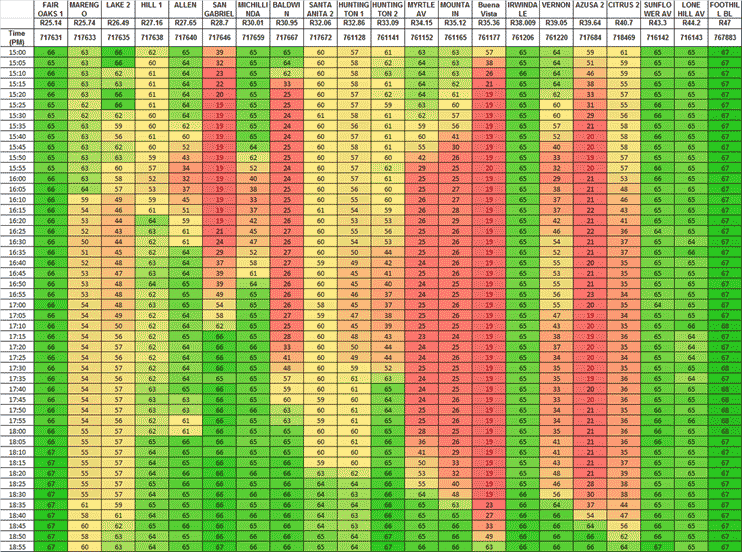
Simulation models produce excellent MOEs that help provide a quantitative assessment of alternatives. The models have the capacity to produce a lot of data. Reducing these data down to a few core tables of essential information is needed for an effective decisionmaking process. Table 19, table 20, and figure 27 are examples of data summaries. The color code in figure 27 indicates the following speeds:
Table 19. Sample MOE summary table.(7)
| Analysis Segment | Design Year | |||||||
| 2005 | 2015 (Alternative A) |
2015 (Alternative B) |
2025 | |||||
| Speed (mi/h) |
Density (vehicles/ lane/mi) |
Speed (mi/h) |
Density (vehicles/ lane/mi) |
Speed (mi/h) |
Density (vehicles/ lane/mi) |
Speed (mi/h) |
Density (vehicles/ lane/mi) |
|
I-94 merge to High Ridge exit |
64 (64) | 11 (6) | 32 (64) | 34 (9) | 64 (64) | 15 (9) | 64 (64) | 16 (11) |
High Ridge exit to High Ridge entrance |
64 (64) | 10 (4) | 7 (64) | 111 (9) | 63 (64) | 14 (6) | 63 (64) | 13 (7) |
High Ridge entrance to |
58 (63) | 12 (4) | 8 (62) | 108 (7) | 61 (64) | 15 (6) | 61 (63) | 17 (7) |
| Note: Table values are listed as XX (YY), where XX represents the morning peak average, and YY represents the afternoon average. Bolded cells represent where the average speed dropped below 30 mi/h for any peak period for that alternative. | ||||||||
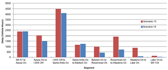
Table 20. Delay comparison between two scenarios in vehicle-hours—I 210 VISSIM simulation.
| Direction | Scenario 13 | Scenario 14 | Difference | Percent Difference |
| Westbound | 14,109 | 10,757 | -3,351 | -23.8 percent |
| Eastbound | 971 | 920 | -51 | -5.3 percent |
| Total | 15,080 | 11,677 | -3,403 | -22.6 percent |

Figure 27. Graph. Speed diagram for I-210 VISSIM simulation.
Graphical Techniques
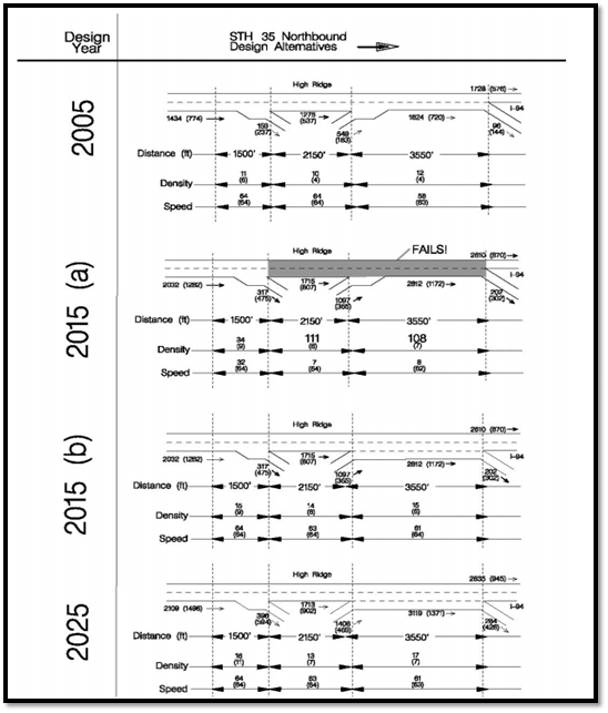
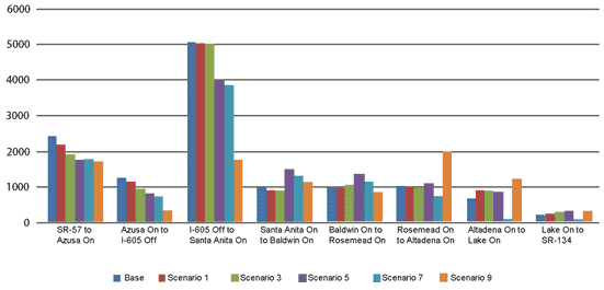
Graphical techniques are another way of representing the simulation analysis results in an effective manner. When developing a graphical representation of data, it is important to clearly explain the criteria for any shading or coloring used to highlight where there may be issues with the depicted operations. Furthermore, it is always good practice to accompany graphics with a corresponding narrative explaining the context, findings, and recommendations. Figure 28 through figure 30 include examples of graphics that can be used.

Figure 28. Illustration. Sample comparison of project alternatives using schematic drawing.(7)

Figure 29. Graph. Delay by segment for two scenarios in vehicle-hours—I-210 VISSIM simulation.

Figure 30. Graph. Delay by segment for all scenarios in vehicle-hours—I-210 VISSIM simulation.