U.S. Department of Transportation
Federal Highway Administration
1200 New Jersey Avenue, SE
Washington, DC 20590
202-366-4000
Federal Highway Administration Research and Technology
Coordinating, Developing, and Delivering Highway Transportation Innovations
 |
| This report is an archived publication and may contain dated technical, contact, and link information |
|
Publication Number: FHWA-HRT-06-139
Date: October 2006 |
|
Maintenance is essential for successful traffic signal and freeway surveillance and management systems operation over time. |
Use of appropriate sensor installation techniques and specification of suitable materials and products will minimize maintenance and other life cycle costs. However, even with superior design and installation, systems do not operate as intended for extended periods if maintenance is not provided. Therefore, proper and regularly scheduled sensor maintenance is critical to effective and prolonged operation of traffic signal control systems and freeway surveillance and management systems.
Many factors can contribute to lack of maintenance. Inadequate budget and staffing deficiencies have a profound effect on the level and quality of maintenance activities. Budgetary problems that continue to plague traffic agencies have resulted in a cost consciousness that frequently focuses only on initial cost, rather than on lifetime cost. Consequently, less expensive products, materials, and processes are used in the original installation because of their lower initial cost. However, this is not always a cost effective life-cycle solution.
While funding problems might not be easily resolved, they may be ameliorated by increased attention to cost effectiveness in all phases of design, installation, operation, and maintenance. Staffing concerns related to numbers and skill levels of maintenance personnel may be reduced somewhat by selecting only equipment that can be realistically maintained by available agency personnel or local contractors.
This chapter is designed to assist maintenance operations managers, supervisors, and technicians in identifying and resolving maintenancerelated issues. Design engineers and those responsible for installation and operations should be fully aware of the cause-and-effect relationship between their activities and maintenance issues.
A number of excellent reference sources address the maintenance process. These include the ITE Traffic Signal Installation and Maintenance Manual,(1) the TRB publication, Maintenance Management of Traffic Signal Equipment and Systems,(2) and the FHWA Traffic Control Devices Handbook.(3)
Sensor maintenance issues associated with inductive-loop detectors have changed considerably over the years. For example, the inductive-loop detector electronics unit, which formerly accounted for a considerable portion of sensor malfunctions, has matured to the point where many currently available digital models seldom experience failure. As stressed continually throughout this handbook, proper installation using appropriate materials and processes is the key to longer sensor system life, lower failure rates, and reduced required maintenance.
There is little question that sensor malfunctions and associated signal failures increase motorists’ time and delay, maintenance costs, accidents, and liability. For example, a simple failure of an inductive-loop detector can cause delay in the traffic flow. If a call is locked in to the controller, it will cause the green to extend to its maximum limit regardless of traffic demand.
In cases where the inductive-loop detector fails without a call, the most common temporary response is to place the phase on maximum recall in the controller. This can increase intersection delay by 50 percent or more.
Although failures cannot be totally eliminated, adherence to proper installation and maintenance procedures can assuredly reduce the incidence of failure and the number of unnecessary maintenance calls. Some of the common causes of failure are discussed below.
When an inductive-loop detector system experiences a failure, it exerts a negative effect on the total traffic signal control system. As discussed in Chapter 5, failures can be categorized by the failure mechanism and cause.
A failure mechanism may be defined as the malfunction that is observed in the operation of an inductive-loop detector system. The following are common failure mechanisms.
An omitted phase occurs when the signal does not service one phase because of the lack of a call from the electronics unit. This is usually caused by a loop failure. Some early electronics units with solid-state outputs would fail in the open position, resulting in no call to the controller. Newer models have circuitry that provides a continuous call if the loop circuit is incomplete. (See "Phase Extending to Maximum.")
A stuck signal is characterized by a signal indication (or phase) not changing as programmed. In most instances, a stuck signal is not caused by the sensor system, but by a controller failure. On occasion, a vehicle not being properly detected may cause a stuck signal. Another cause of a stuck signal is an inductive-loop electronics unit, operating with the delay feature, not retaining the call for a sufficient time to be transmitted to the controller.
This situation occurs when a specific phase of the signal operation extends to the maximum time set on the controller regardless of traffic demand. This is typically caused by a continuous call from the inductive-loop electronics unit and can generate extra delays of up to one-half the normal daily delay. The continuous call may be the result of a faulty electronics unit or an open loop circuit.
Low sensitivity of the loop or the electronics unit (or a combination of both) can result in intermittent problems. Unstable oscillators in the electronics unit may also cause intermittent problems during periods of rapid temperature shifts. However, many current electronics unit models are capable of retuning. When the problem persists for no apparent reason (called ghost problems), the electronics unit is usually replaced.
A broken loop wire that will ordinarily cause a malfunction may reconnect itself with shifts in pavement and cause intermittent operations. The only cure for this situation is to replace the loop when the process of elimination has determined that the only remaining cause could be a broken wire.
External devices that have been installed to provide additional lightning protection may have been damaged by a power surge. This may result in intermittent operation. Since this damage may not be visible, these devices should be checked if intermittent operation occurs.
Crosstalk is the result of inductive or capacitive coupling between loops or lead-in wires. Crosstalk may produce false detections when there are no vehicles in the detection zone. It may also result in lockup following a vehicle detection. It is usually associated with motion in either the generating or receiving loop channels due to transient frequency alignment caused by a vehicle-induced signal.
Crosstalk occurs when the normal operating frequency of one loop installation is influenced by the frequency of another. This normally arises when the frequency of one loop system is decreasing and passes through or near the frequency of the other loop. Electrical engineers refer to this as a frequency lock between two oscillators.
This condition occurs only when the frequencies of the two oscillators are close to each other and electronic coupling exists between the two oscillators. There are numerous sources of electronic coupling. Some of the more common include:
The false detection of vehicles outside the detection zone is called splashover. This problem often occurs when long loops are operated at a sensitivity level required to detect small vehicles (i.e., motorcycles). With this high sensitivity, vehicles from adjacent lanes may be falsely detected. This problem also occurs when the loop is placed too close to the lane line. Splashover is a problem between lanes controlled by different phases. It is not a problem between lanes on the same phase unless accurate vehicle counts are desired.
As discussed in Chapter 5 and Appendix M, surveys of traffic agencies indicate that there are eight major causes of loop failure. These are:
Many agencies report that most of their maintenance problems involving inductive-loop detectors can be directly attributed to installation errors. These errors can be a direct result of sloppy installation, poor inspection, and the use of low-grade components not suited to the particular environment.
Many agencies do not use their own personnel to install inductive-loop detector systems. In these cases, the contract to install the systems is usually awarded to the lowest bidder. The lowest-bidder concept has been successful in encouraging competitive bidding and generally lowering costs. To be effective, however, a procuring agency must apply stringent prequalification guidelines to avoid awarding the contract to an electrical contractor with inadequate experience or knowledge.
If inspection is inadequate, the potential for contractor expediency and error is enormous. The consequences of improper shortcuts or errors may not surface until the contractor’s responsibility has elapsed and, therefore, the loop must be repaired at the expense of the agency. For example, piercing, cutting, or otherwise damaging the insulation on the loop wire by the use of improper tools or careless handling may not show up until some time after the wire is sealed in the slot.
In Chicago, IL, IDOT maintains more than 18,000 inductive-loop detectors. Because of their past experience with loop failure, they initiated an active inspection and maintenance program to monitor each loop. This program has reduced replacements to about 35 recuts per year. They report that no more than 5 percent of their loops are inoperative at any given time.(4)
The analysis of a malfunctioning inductive-loop detector can be a difficult task. The root cause of the failure may be associated with environmental conditions or other factors attributed to installation. The technician analyzing a faulty inductive-loop system should consider all the causes of failures listed above. Initially, of course, it is necessary to isolate the problem to one associated with the sensor system.
An experienced technician is frequently able to pinpoint the troubled area or faulty part by visual examination. Figure 6-1 shows a readily apparent pavement failure along the saw slot, which has exposed loop wires. When visual inspection does not immediately disclose the problem, systematic troubleshooting is required. Such procedures for identifying and correcting malfunctioning inductive-loop detector systems are discussed below.
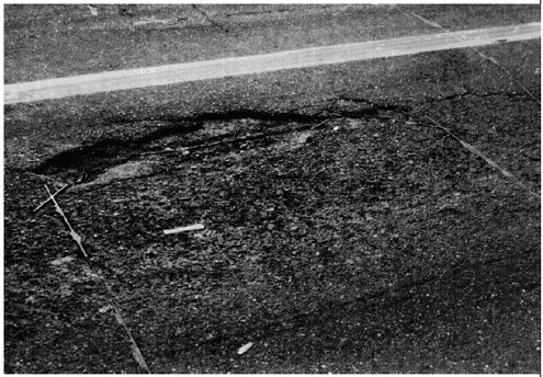
Figure 6-1. Pavement failure near an inductive-loop installation.
The hostile street environment makes the loop wire the most vulnerable component of an inductive-loop detector system. Therefore, a scheduled visual inspection of the roadway at and around the sawcut should be conducted every 6 months to determine if the integrity of the pavement, the sealant, or the slot has been violated. The inspection should include looking for wires that have floated to the top of the sealant. Loops with exposed or shallow-buried wires should be replaced. The early detection and correction of saw slot problems can prevent many future inductive-loop detector system malfunctions.
Unstable, cracked or deteriorating sealant should be removed with a blunt instrument. The slot should be blown clean with compressed air and new sealant poured over the old. This is especially important in areas where snow removal equipment is used and salt applications are prevalent.
Potholes within the loop area should also be repaired. The two major factors influencing quality pothole patching are material selection and repair procedures. Thus, these factors control the cost effectiveness of the overall patching operation through associated material, labor, and equipment costs. The combinations of materials and procedures that produce optimum cost effectiveness vary from agency to agency.(5)
Materials available for pothole repair in asphalt concrete include stockpiled cold mix materials, spray-injection heated emulsions, and hot mix asphalt concrete. FHWA reports provide detailed instructions for repairing potholes and spalls in asphalt surfaced pavements and portland cement concrete. (See references 5–10.)
A low value of inductance is the usual cause for inadequate loop sensitivity to detect a vehicle. Low inductance can be caused by an insufficient number of turns of wire, by turns of wire shorted together, or by steel mesh in the roadway that has produced a shorted-turn effect. If any of these factors are present in a multiple-loop configuration, the condition can be temporarily corrected by removing the defective loop from operation.
Multiple loops can be connected in series or series/parallel to maintain an equivalent inductance within the range needed by the electronics unit. Quantitative measurements are made to determine if the inductance of a malfunctioning system has dropped below the acceptable value. Several test meters are commercially available to measure inductance. Some of these perform direct measurements, while others measure frequency, which is inversely related to the inductance value. In the latter case, accompanying charts or graphs are used to determine inductance.
Crosstalk may occur when any of the following conditions are present:
Potential solutions to these problems are listed below.
Caltrans uses a modified loop tester and the following four-step procedure for identifying and correcting crosstalk:(11)
If wire loops are causing the crosstalk, they can be reassigned to different channels or the lead-in wires in the pull box can be retwisted and respliced, thus eliminating one cause for potential crosstalk.
To identify which electronics unit is cross talking, one general procedure is to disconnect all units except those that have the most frequent false calls. If no new false calls or lockups occur, then crosstalk from another unit is indicated. By selectively reconnecting the other electronics units, the unit causing the crosstalk between wire loops can be identified.
Specific multichannel electronics units have a scanning feature that reduces potential crosstalk. In these units, the sequential scanning system activates one loop channel at a time, while the remaining loops, connected to other channels, are deenergized and thus unable to provide coupling to the active channel. This does not, however, eliminate crosstalk between channels on different electronics units. Frequency separation will reduce crosstalk between adjacent loops as well as other wire loop detectors.
Experience indicates that older electronics units cannot be freely substituted for each other. Tests in Los Angeles, CA, revealed that "…there are some brands of electronics units that appear…to have more sensitivity than others…Certain brands and/or types will not operate with adverse conditions such as very low circuit Q or a low value of shunt resistance to the conduit ground."(12) It was concluded that the inductance value at the cabinet end of the loop system must fall within the operating range of the units if they are to be interchanged. Newer electronics units having the same characteristics and quality can generally be interchanged without problem, since different manufactured units operate on different frequencies; however, any unit that passes the NEMA tests can usually be interchanged.
Each unit within an agency’s inventory should be checked for sensitivity to ensure that all electronics units achieve minimum sensitivity. After this check has been made, the substitution process can be used to determine if the electronics unit at the malfunctioning installation is the cause of the failure. Thus, if the electronics unit is replaced and the system functions normally, this may indicate a failure in the electronics unit. Conversely, if loop system operation does not improve with the substituted unit, then the original unit is reinserted and another problem source determined.
Since many malfunctions are crosstalk-related, any change that affects the loop frequency will improve the situation, at least temporarily. Therefore, substitution of another unit, even of the same model and frequency setting, will often return the loop to normal operation due to small differences in the values of the input capacitors in the electronics unit. Substitution of a different model (especially from a different manufacturer) is often successful due to differences in front-end electronics design. The best solution is to eliminate, to the maximum practical extent, those elements that contribute to crosstalk.
Several operational checks can be conducted to expedite analysis of a malfunctioning inductive-loop detector system. These checks can be performed utilizing a maintenance vehicle and a vehicle simulator that analyze adjacent lane detection, motion in the loop wire, intermittent detection, and sensitivity of the loop system.
At locations where adjacent lane detection is suspected (such as where long loops are used on left-turn lanes), one technique is to maneuver the maintenance vehicle close to the lane and monitor the electronics unit. The sensitivity is then adjusted so that the maintenance vehicle does not cause an output. However, the sensitivity must not be set too low to prevent the electronics unit from detecting a small vehicle in the detection zone.
It should be noted that this procedure does not test the worst case. The worst case occurs when several vehicles are stopped in the adjacent lane and occupy the entire length of the long loop.
Several loop configurations avoid or minimize adjacent lane detection, e.g., a series of small loops, quadrupole loops, adjustable diamond loops, and others that are described in Chapter 4. When it is not possible to change loop configurations, delay timing can be utilized to detect a vehicle only if it is in the detection zone for a specified amount of time (say, 5 seconds). With this approach, passing vehicles in an adjacent lane are not detected, although stopped vehicles may present a signal large enough to hold the call in the empty lane.
The beginning of loop failure is often associated with intermittent operation. As stated earlier, causes of this type of operation are generally poor connections, open loops, short circuits, or leakages to ground. These, in turn, may cause the electronics unit to lock up when a motor vehicle passes over the point of the fault.
To identify this problem, the operation of the inductive loop is observed while the maintenance vehicle is driven over the various loops suspected of having intermittent operation. Operation of the vehicle in the detection area can also assist in identifying problems associated with wire motion. Another approach to identifying sources of intermittent operation is to visually inspect all connections and test them with a 500-volt megger and a low-ohm midscale ohmmeter.
A simulated vehicle that represents the smallest detectable vehicle can be used to determine if the inductive-loop system sensitivity is in balance and to determine the minimum sensitivity required of the system. The same procedure can also be used to test new installations. Caltrans uses a shortedturn vehicle model to simulate a 100 cc Honda motorcycle. The simulator is placed in the detection zone, and the electronics unit is observed to determine if the vehicle is detected. Reference 11 provides the construction details and procedures for using this model.
The simulated vehicle is utilized to measure the change in inductance, which is a measure of the sensitivity. For this purpose, a frequency reading is made with no vehicle present; then the simulated vehicle is introduced into the detection area and a new frequency reading is taken.
The difference between the two frequencies provides a measure of the change in inductance due to the presence of the vehicle according to:
| (6-1) |
This is an approximate relationship valid for changes in inductance up to 10 percent and for loop quality factor Q greater than 5. This equation shows that the percent change in inductance is twice the percent change in frequency as was discussed in Chapter 2.
Table 6-1 identifies several malfunctions that occur in inductive-loop detector operation and their causes. Potential causal factors for each listed malfunction are identified by an "X" in the appropriate table cell. Maintaining the correct resistance values and knowledge of the inductance values required for proper operation of the electronics units will eliminate many of the problems associated with loop performance.
 |
No call | Constant call | False call | Drifting | Crosstalk | Will not tune | Unbalanced sensitivity |
|---|---|---|---|---|---|---|---|
| Low quality factor |
X | X | X | ||||
| Low resistance to ground |
X | X | X | X | X | ||
| High series resistance | X | X | X | X | X | ||
| Improper inductance | X | X | X | X | |||
| Poor ground | X | X | |||||
| Improper installation | X | X | X | X | X | X | |
| Electronics unit malfunction | X | X | X | X | X |
Four devices are needed to analyze loop systems:
Low resistance-to-ground and high series resistance are major contributors to loop system malfunctions. Low resistance-to-ground can result from poor insulation on the loop or lead-in wire or inadequate sealing of splices. These problems can be avoided if, during installation, the materials are handled properly and appropriate splice sealing methods are followed. Low resistance-to-ground can also occur when wires are exposed as a result of pavement cracking, sealant cracking, frost action, and wear to pavement from studded tires. In addition, excess wire coiled in the pull box or controller cabinet can add inductance to the circuit. This may result in tuning problems. There is also an increased potential for coupling to another loop system.
Poor splices, corroded or loose screw terminals, poor crimping, or inadequate wire size can cause high series resistance. High series resistance is a problem exacerbated by humidity, temperature, and vibration, which cause drifting and false calls. These are the same problems that occur when the system has low resistance-to-ground.
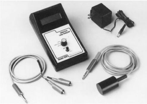
Figure 6-2. Model ILA-550 inductive-loop system analyzer. Measures the leakage resistance of a loop to ground at 500 V dc; frequency and relative signal strength of a loop network; loop inductance, resistance, and Q; and change in inductance caused by vehicle driving over a loop (Photo courtesy of US Traffic Corp., Santa Fe Springs, CA).
The following equipment is required to isolate the causes of erratic operation or malfunction of an inductive-loop detector system using the procedures discussed below:(12)
Figure 6-3. Quality factor Q data form.
Figure 6-4. Sensitivity S data form.
Figure 6-5 shows a loop finder, which can be used to locate a loop when pavement overlays cover the loop installation.
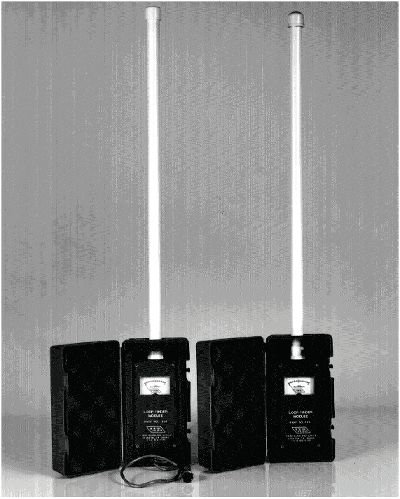
Figure 6-5. Loop finder.
The six steps described below assist in isolating the causes of inductive- loop detector system malfunction or erratic operation.
Check for indication of broken or cut loop or lead-in wires. Check for open leads within the controller and for the connection of the power source to the electronics unit.
To eliminate the electronics unit as the source of the problem, replace the existing unit with one having a known sensitivity. If the operation is not considerably improved, remove the substituted unit, replace the original unit, and continue to Step 3.
One manufacturer notes that since many problems are crosstalk-related, any change that will affect the loop frequency will improve the situation, at least temporarily. As discussed above, substitution of an electronics unit, even of the same model and frequency switch settings, will frequently be successful in eliminating the problem due to subtle differences in the values of electronics unit input capacitors. Therefore, substitution of electronics units may solve the problem temporarily without addressing the real problem. If the problem is crosstalk-related, the most effective solution is to identify and eliminate the causes of the crosstalk.
Measure and record the following data on the quality factor data form.
To determine the Q of the loop system, follow the procedure described below and record the results on the quality factor data form:
Record the frequencies obtained from either of the following methods on the sensitivity data form.
Method 1
Method 2
Perform the analysis by comparing the measured values for each of the items with the values shown in the "Indicated Conditions" column in Table 6-2. Determine the required maintenance from the suggested "Corrective Actions" listed in the table.
Conventional magnetometer systems are composed of the sensor probe, probe cable, lead-in cable, and the electronics unit. The same precautions should be observed for the probe cable and lead-in (home run) cable as with an inductive-loop detector lead-in wire and lead-in cable. Magnetometers that transmit data via RF transmission to the electronics unit do not require a probe cable, but do need a lead-in cable that connects the antenna (that receives the transmitted data) to the electronics unit in the controller cabinet. A magnetometer probe cable, when required, is placed in a slot in the road surface and should be sealed with the same care and procedures as used for inductive-loop detector lead-ins. The splices connecting the probe cable and the lead-in cable must be mechanically and electrically sound and environmentally protected, as described in Chapter 5.
Failure can occur in any of the subsystems. The principal causes of magnetometer failures are described below.
Four key areas can affect the operation of a magnetometer system. These are proper burial depth of the sensor probe, stability of the probe in the pavement, characteristics of the probe cable with regard to moisture penetration, and saw slot maintenance.
Vertical placement of the probe is critical to system performance. Deep placement of approximately 24 inches (60 cm) will provide good single-count detection, but will result in lower signal levels. Shallow placement of about 6 inches (15 cm) will provide a stronger signal, but will also increase the potential for double counting. Therefore, the burial depth must be appropriate for the intended application, as described in Chapters 4 and 5.
Probes must be firmly supported in their holes. Any displacement of the vertical alignment of the probes may result in performance instability. A recommended installation approach is to utilize PVC conduit as a shell, with sand tamped around the probe to prevent lateral displacement.
Water-blocked cable must be used to prevent moisture penetration. Any moisture can cause excessive capacitance or leakage between wires or to ground. In addition, moisture across the connections to a magnetometer may induce drift. Wherever possible, it is recommended that the probe cable run directly to the electronics unit, thus eliminating splices. If this is not possible, splices must be electrically sound and environmentally protected.
| Item | Indicated conditions | Corrective actions |
|---|---|---|
| Loop wires | Broken, cut, or exposed insulation worn away | Install new loops shifted by 6 inches (15 cm) from the old loop and cut each old loop at least twice |
| Loop slots | Sealant missing Wire exposed Surface eroded | Clean slot of loose material and refill or replace entire loop and lead-in as required Patch street surface if loop wire is not exposed |
| Resistance to ground | 100 MΩ (megohms) or more Shorted | Acceptable if Q > 5 Replace as required |
| Series loop resistance | Open circuit Greater than specified (based on wire size and length) | Locate and correct open circuit Isolate cause (poor splice, inadequate crimp, etc.) and repair as required |
| Quality factor | >5 if RP >100 MΩ <5 for any other value of RP | Acceptable with modern electronics units Replace electronics unit |
| Sensitivity of loop system | Measures lower than design value for the configuration | Consider Q, shunt RP, and series RS as possible causes and correct as indicted Determine loop interconnection and rework to accepted design values |
| Sensitivity of electronics unit | Remains actuated Does not actuate Insufficient sensitivity | Substitute known serviceable electronics unit Substitute known serviceable electronics unit Substitute and return unit removed to shop |
| a | The limiting values in the table are nominal values determined from the original investigation. They may require modification to incorporate additional experience. |
The sawcut for the magnetometer should be visually inspected every 6 months to evaluate the condition of the sealant and the surrounding roadway. As with the inductive-loop sawcut, any cracking or deteriorating sealant should be chipped away, blown clean, and replaced with new sealant.
The initial step for troubleshooting problems with magnetometer systems is to visually inspect all system components, including the connections at the terminal strip in the controller cabinet, any splices in pull boxes, and the street installation of the probe and probe cable. These components should be examined for loose connections, poor sealant, exposed wires, bad splices, or evidence of recent construction.
If none of these elements show evidence of problems, the next step is to examine the probe for tilting. Without retuning the electronics unit, use a bar magnet oriented in a direction which adds to the vertical component of the Earth’s magnetic field intensity (as described in Chapter 5) to measure the distance from the road surface that will cause the detection to occur. Compare this measurement with the one taken at the time of installation.
If the distance is smaller than the original measurement, then the probe may have tilted due to pavement movement. If the probe has tilted, the electronics unit may be retuned and this location monitored frequently for evidence of further tilting. If the unit cannot be retuned, the probe should be pulled and reinstalled with proper vertical alignment.
One way to compensate for the tilting problem is to use a Digital Nulling Loop such as that developed for the City of Baltimore, MD.(13) This device has automatic compensating circuitry, which is incorporated into the electronics unit. It works similarly to an inductive-loop detector in tracking environmental changes. One of these devices is required for each channel in the electronics unit.
If detection does not occur during the test for tilting, the problem could be in the cable, wire, probe, splice, or electronics unit. Series resistance and resistance-to-ground measurements should then be made at the controller cabinet with a VOM. The series resistance should be within 10 percent of the measurements made at installation and the other readings should be high, indicating no breaks in the insulation or in the integrity of the environmental splice.
If the measurements do not fall within these ranges, the next step is to determine whether the problem lies in the probe, the probe cable, the splice, or the lead-in cable.
The splice should be taken apart and the following tests conducted. A series resistance and resistance-to-ground measurement toward the probe should be made and compared with measurements taken during installation. Large variations indicate faulty probe or probe cable. The best solution is to replace the probe and probe cable.
On the other hand, if the measured values compare favorably with the original values, the top pair of the lead-in cable wires should be tied together and the VOM read. This should be repeated with the bottom two wires. If these values are high, the lead-in cable should be replaced. If not, the problem originates in the splice and a proper reconnection of the splice is needed to eliminate the problem.
If this systematic method is used, the problem will usually be identified. The original reference sheet should always be referred to during this process to compare measurements. When the problem has been rectified, new values should be noted and retained for future reference.
Magnetic detectors have an extremely good maintenance record. As they are installed under the road surface and all lead-in wires consist of cable encased in underground conduit, the opportunity for failure is relatively small. User surveys indicate that these sensors do not present any major maintenance problems, and that some of these devices have been installed for more than 20 years without a failure.
In the rare case where a magnetic detector fails, the first step is to examine the electronics unit. When false responses occur (the electronics unit output relay closes when no cars are crossing the detection area), replace the existing unit with another tested unit, tune, and monitor. If the system then works, it can be assumed that the original unit was at fault. If the system still does not work, a series resistance test followed by a resistance-to-ground test is required. This should identify any leakage in the system.
The total circuit resistance-to-ground of the detector should be measured after disconnecting all of the jumpers to ground and the leads to the relay. In cases where leakage is between detector cables and signal cables, a 1- megohm leakage may result in erratic operation. Proper cable layout and good splicing can avoid this condition. Occasionally, one probe circuit will pick up more extraneous signal than another probe circuit on the same phase. If this occurs, interchange probes at the terminal strip so that the probe circuit picking up the largest extraneous signal is at the "Magnetic Detector Minus" side of the system.
If the voltmeter needle moves erratically when there are no vehicles passing the probes, it generally indicates surges in nearby power wires. If the probe can be located closer to traffic, the sensitivity of the electronics unit can be decreased to reduce the effect of power lines. Changing the orientation of the detector axis can eliminate or minimize the effect of a particular power line. For minimum disturbance, the detector axis should be parallel to the power lines.
Relay units are designed to be immune to all line voltage changes except extreme ones. If line voltage changes are suspected of causing the voltmeter needle to behave in an erratic manner, disconnect the "Magnetic Detector Plus" and the "Magnetic Detector Minus" leads, and short them together. If the voltmeter needle is still erratic, the trouble is due to line voltage changes. In this case, examine the power service connections to make sure they are properly soldered and insulated. If there are no obvious problems, request that the power company check the regulation of the power being supplied and make any necessary modifications to their equipment.
If the voltmeter needle tends to behave erratically only when the signals change (with the magnetic detector terminals short-circuited), the trouble is insufficient current-carrying capacity in the service wires between the cabinet and power source.
If the voltmeter needle is steady when the electronics unit operates with the detector leads shorted and tends to be erratic when the signal lights change with the detectors reconnected, then the difficulty is caused by electromagnetic or electrostatic induction between the wires carrying signal currents and the wires leading to the magnetic detectors. Make sure that the capacitors are in place across the terminals to which the magnetic detectors are connected, as these capacitors are designed to absorb such surges.
Fluctuations on the neutral power wire with respect to ground might also cause intermittent response. A connection to a conducting rod driven into the ground (required in most modern installations) can stabilize this condition. If the connections are stable, check for leakage in the detector circuit by making the same tests that were described above with a VOM.
Other problems could involve induced voltage response, which can occur when the detector leads are placed in the conduit with the power supply leads. Induced voltage can cause false responses. Consequently, the lead-in cable should not be inserted into conduit with other signal wiring. Another cause of false response is setting the gain too high. Reducing the gain on the electronics unit will generally solve this problem.
Maintenance and life cycle costs may be determined, in part, by published values of the mean time between failures. Some over-roadway sensors are designed with mean time between failures of 64,000 to 90,000 hours. The effects of lightning strikes and other natural or human-induced failure modes are not included in this number. Thus, maintenance and replacement costs for these devices may be significantly less than for inductive loops over a 10- year period, especially if commercial vehicle loads, poor subsoil, inclement weather, and utility improvements frequently require road resurfacing and loop replacement.
Some agencies require lane closures at night and traffic diversion for installing or repairing in-roadway sensors on freeways. Such requirements create significant differences between the cost of freeway and arterial sensor maintenance. Other maintenance items, such as electronics unit retuning, are generally not needed with over-roadway sensors. However, new maintenance requirements, such as camera lens cleaning, can arise.
The most pervasive maintenance operation for video image processors is the periodic cleaning of the camera lens. The cleaning frequency varies from six months to one year, depending on the camera mounting height, the truck traffic volume, and precipitation and dust characteristics of the monitored area. Cleaning may be performed by the agency responsible for traffic management or may be contracted out. Cameras mounted on the tallest poles (e.g., 70 feet (21 m)) may require more specialized boom trucks for cleaning.
Radar sensors do not appear to require much maintenance. EIS Electronic Integrated Systems Inc., the manufacturer of the RTMS, reports that of 624 units shipped to one North American client, 10 (or 1.6%) were returned for repair from April 1994 through June 2002.
A 10-year study of inductive-loop maintenance costs in Houston, TX, found as few as 42 failures and as many as 341 failures per year in the 600 to 1000 intersections maintained during the 1989–1998 study period. The calculated loop replacement costs per intersection varied from $107 to $628 (U.S.).(14) Actual costs per intersection are probably higher because the calculation assumes all intersections had loops (some were not actuated and hence did not use loops), 100 percent of loop failures were discovered (some were not), and no maintenance besides replacement was performed.
In a summary of maintenance costs of four Autoscope VIP systems used by the Road Commission of Oakland County, MI, TTI found that monthly camera maintenance averaged $5.05 and monthly processor maintenance averaged $26.71 from 1995 through 1998. A total of 692 cameras and 194 controllers were included in the study. Costs included labor, fringe benefits, and truck, lift, and radio equipment. Because the VIPs were under warranty for at least part of the time, the manufacturer or distributor paid for some repair parts and new replacement units. Therefore, older units whose warranty period has expired may experience higher maintenance costs.(14)
Table 6-3 compares the annualized per-lane cost for inductive-loop detectors, VIPs, multiple detection zone presence-detecting microwave radar, and acoustic array sensors for a six-lane freeway sensor station.(14) Motorist delay and excess fuel consumption incurred during installation further add to the annualized cost of the inductive loops.
| Sensor | Number required for 6 lanes | Expected life | Annualized cost |
|---|---|---|---|
| ILD | 12 | 10 | $746 |
| VIP | 2 cameras, 1 processor | 10 | $580 |
| Multidetection zone microwave presencedetecting radar | 1 | 7a | $314 |
| Acoustic array | 6 | 5 | $486 |
| a | Manufacturer’s mean time between failures suggests a 10-year expected life. |
Previous | Table of Contents | Next
FHWA-HRT-06-139 |

