

| Contents | Next >> |
Connection Details for PBES
Introduction
The Federal Highway Administration (FHWA) has undertaken a program called Highways for LIFE. The word "LIFE" in this program title is an acronym for:
L = Long lasting
I = Innovative
F = Fast construction
E = Efficient and safe
The thrust of this program is to change the way we design and build our highways. A former Deputy Secretary for the US Department of Transportation put it best when he stated:
"Change the way we build highways. We need to build them faster, have them last longer, have them be safer and at a lesser cost. Be BOLD and AUDACIOUS in your thinking."
The Highways for LIFE program motto is: "Get In, Get Out, and Stay Out". The first two portions of the motto are self explanatory. The "Stay Out" portion refers to the inherent lasting quality of prefabricated components that are produced in the controlled environment of a fabrication site. Just because something can get built fast does not mean that we need to sacrifice quality. In fact, the exact opposite is true. We can build highways faster and better.
The focus of this Manual is on connections used in prefabricated bridge construction. Prefabrication is not a new concept. The vast majority of bridges built today employ some form of prefabrication. Steel and pretensioned concrete beams are two of the most common prefabricated components. Using prefabrication, large portions of the structure are manufactured off site before construction begins. There are many benefits to the use of prefabricated components; however, this Manual will focus on prefabrication as a means of accelerating bridge construction.
Numerous agencies have experimented with rapid construction techniques when bridges needed to be constructed quickly. There have been many successes, and a few failures. The next logical step in the evolution of this process is to make accelerated construction more commonplace and effective.
This type of evolution is not unprecedented. Forty years ago, parking garage structures were constructed primarily with cast-in-place concrete (either all concrete or concrete on steel framing). Today, in most parts of the country, total precast concrete parking structures are the norm and construction times for these structures have been dramatically reduced as a result. The fact that structures using prefabricated elements and systems are common in a competitive construction market also indicates the economies of this type of construction.
Accelerated Construction Technology Transfer Program (ACTT)
The FHWA has sponsored numerous three-day workshops under their Accelerated Construction Technology Transfer Program (ACTT). During each workshop, a team of national experts visited a state highway agency to brainstorm on a particular project proposed for accelerated construction techniques. Each workshop provided the state agency with a wealth of information to be used as the building blocks for a successful accelerated construction project. During these workshops, the following were identified as common needs for successfully implementing accelerated bridge construction:
- Quality details
- Long-term performance and durability
- Design methodologies and training
- Construction methodologies
Manual Intent
This Manual is intended to focus primarily on the first three items listed above. Construction methodologies have been partially addressed in previous FHWA manuals and will be further addressed in a future FHWA manual.
This Manual has been prepared through the perspective of an owner agency. It is intended to be used by bridge design engineers at the structure type study phase of a design project. Each bridge will have unique design constraints. The details included in this Manual are not intended to be simply inserted into a design. The bridge design engineer will need to adapt each detail for the specific geometric criteria and structural demands that are anticipated.
The development of a manual on connection details for prefabricated bridge elements and systems must evaluate what techniques have been used in the past. To be considered viable, any connection detail or process needs to pass a test:
- Does it result in a rapid construction process?
- Does it transmit the forces between elements and systems effectively?
- Is it durable?
- Has it performed well under traffic and in exposed environments?
- Is it cost effective?
- If a process or connection is proprietary, can it be incorporated into numerous projects without producing contracting issues?
If the answer to any of these questions is "no", then the connection should not be considered. The details included in this Manual have passed this test. Performance ratings are given for each detail. In most cases, these ratings were assigned by the agency that submitted the detail and are, therefore, subjective. Users of this Manual should critically evaluate each detail and judge whether it is appropriate for the intended use. The agency and person who submitted each detail are listed. Users are encouraged to contact these engineers for further information on specific details.
Sources of Details
This Manual includes a compilation of details used by various agencies. The vast majority of connection details have been put into practice on bridges. There are several details in the Manual that have not been used on actual bridges; therefore, these are labeled as conceptual.
The details in this Manual were obtained by a solicitation to all 50 state highway agencies; 19 state highway agencies responded. Federal agencies, suppliers, industry groups and fabricators were also contacted. The details that met the criteria listed above were sent to the authors for development of this Manual. In many cases, the details were simply copies of the original contract plans. These details were re-drafted in order to present a consistent representation throughout the manual. The authors recommend that users of this Manual contact the agency that provided the detail if there are questions. To assist the user, the following information is presented for each connection included in this Manual:
- Agency providing the detail
- Contact person's name, address, telephone number, and e-mail address
- Project description
It is understood that not all contact persons may be available in the future. However, with the information provided, a user should be able to locate persons in each agency who are familiar with the details.
The details provided in this document by no means represent all prefabricated bridge construction projects in the United States. The authors are aware of numerous other projects that were not submitted by the owner agencies. In addition, there are numerous planned prefabricated bridge construction projects that are either in construction or awaiting bidding. Designers should keep apprised of further developments in prefabricated bridge elements and systems through the Federal Highway Highways for LIFE website at: www.fhwa.dot.gov/hfl/
Manual Format
The Manual has been divided into four chapters. Chapter 1, "General Topics," addresses issues that are common to most connections in bridge construction. Chapters 2, 3 and 4 address issues which are specific to the major portions of typical bridges, in accordance with the terminology in the AASHTO LRFD Bridge Design Specifications [1]:
Chapter 2: Superstructures: Decks, beams, stringers, modular superstructure prefabricated systems, connection between superstructures and substructures, and miscellaneous superstructure details
Chapter 3: Substructures: Piers, abutments, walls (to top of footings)
Chapter 4: Foundations: Footings, piles
This Manual is formatted to help users find the correct detail through a logical hierarchy that will be consistent with a web site application. The chart in Figure 1 depicts this Manual layout:
Figure I-1: Manual Format
(Click image to enlarge)
Detail Classification
To help users of this Manual understand the practicality of each detail, the authors and members of the FHWA Office of Bridge Technology Staff developed a level classification that categorizes each detail based on its frequency of use and effectiveness. This level classification is somewhat subjective; however, it provides the user a measure of effectiveness of the detail. By assigning these levels, the authors and the FHWA staff do not endorse or guarantee the performance of each detail. Users of this Manual are reminded that sound engineering judgment must be applied to all bridge designs.
Three classifications have been developed for this Manual based on the following general criteria:
Level 1
This is the highest classification level. It is assigned to connections that have been used on multiple projects or that have become standard practice by at least one owner agency. Level 1 details are typically practical to build and will perform adequately.
Level 2
This classification is for details that have been used only once and were found to be practical to build and have performed adequately.
Level 3
This classification is for details that are either experimental or conceptual. Some Level 3 details have been researched in laboratories, but to the knowledge of the authors, have not been put into practical use on a bridge. Also included in the Level 3 classification are conceptual details that have not been studied in the laboratory, but are thought to be practical and useful.
Connection Detail Data Sheets
The authors intend users of this Manual to be able to "shop" for details for use on new projects. To facilitate this use, the details are presented on simple two-page data sheets that can easily be removed and copied from the Manual. Each data sheet contains the following information:
Originating Organization Information:
This information includes the organization, contact person information and a description of the project where the detail was used.
Connection Details:
In most cases, the original contract details are presented; when available, multiple details are presented in order to properly present each connection.
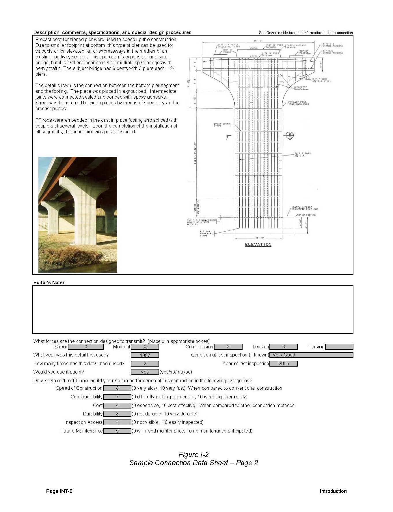
Description, Comments, Specifications and Special Design Procedures:
This section contains additional information on the connection including design information and issues that may have been encountered during the construction of the connection. If photographs were available, they are presented in this section.
Performance Data:
This section contains information on the age and durability of the connection. Agencies were asked to rate the performance of each connection on a scale of 0 to 10 as part of the submission. The ratings include:
- Speed of Construction
- Constructability
- Cost
- Durability
- Inspection Access
- Future Maintenance
Figure I-2 presents an abbreviated sample connection data sheet.
Figure I-2
Sample Connection Data Sheet - Page 1
(Click image to enlarge)
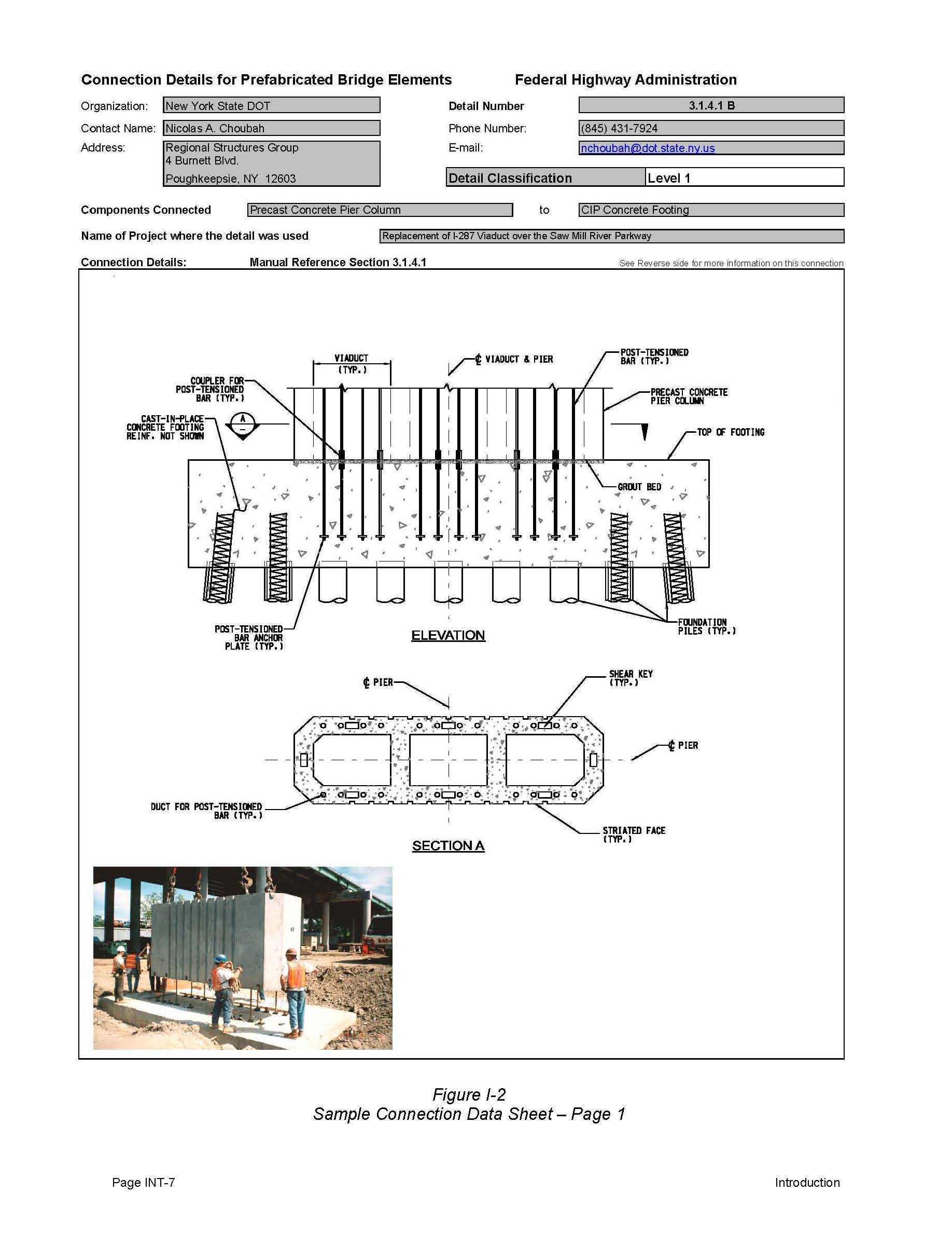
Figure I-2
Sample Connection Data Sheet - Page 2
(Click image to enlarge)
| Contents | Next >> |