

| << Previous | Contents | Next >> |
Connection Details for PBES
Chapter 1 - General Topics
1.1 Benefits of Prefabrication
There are numerous benefits to the use of prefabrication beyond accelerated bridge construction. Prefabrication can improve the quality of bridge elements and systems since they are constructed in a controlled environment using high quality materials and standardized production processes. Improved quality leads to an extension of the structure service life. Prefabrication can also reduce bridge construction costs and life-cycle costs.
A major advantage of prefabrication is that it can reduce onsite construction time, resulting in several key benefits when compared to conventional on-site construction practices:
- Traffic: The disruption of traffic is often cited as a reason for using accelerated construction techniques. Reduction in lane closures and the number of days of traffic detours can have a measurable affect on the user costs of a highway system.
- Safety: By reducing the amount of construction that takes place at the site, the amount of time that construction crews and motorists are exposed to the dangers of work-zones is also reduced. In addition, prefabrication can improve construction crew safety when working over water or in hazardous conditions such as when construction is adjacent to high voltage power lines.
- Environmental: Often environmental permitting requirements limit onsite construction, for example, to certain seasons of the year. These limitations effectively reduce the number of available calendar days for construction. Prefabrication and accelerated construction can keep a project on schedule even with fewer available working days and other environmental limitations at the site.
- Weather: As with environmental constraints, many areas of the country have limited work seasons due to severe winter weather. Prefabrication and accelerated construction can be used to complete more construction during a short construction season.
1.2 Accelerated Construction Overview
This section includes a brief overview of the accelerated construction process for bridges. Several FHWA documents on accelerated construction already exist and are hereby referenced to supplement this section:
- Decision-Making Framework for Prefabricated Bridge Elements and Systems (PBES) [2]
- Manual on Use of Self-Propelled Modular Transporters to Remove and Replace Bridges [3]
A future FHWA manual is planned that will present information on accelerated bridge construction systems and processes that are not directly related to connections. This manual will include concepts such as total bridge prefabrication and installation.
1.2.1 When to Use Accelerated Construction
There are a number of scenarios where accelerated bridge construction is appropriate. On many projects, construction of the bridges is the critical path to the overall completion of the project. This may not be the case for large roadway projects where there are few bridges. In this case, the roadway construction is usually the critical path.
At this time, there can be a cost premium for using accelerated bridge construction techniques. Many designers believe that this will change in the future as more accelerated bridge construction projects are undertaken. Contractors and fabricators will continue to become more proficient in the techniques, thereby improving the economy of accelerated construction. Other common scenarios that can offset or justify additional costs for accelerated construction include:
- Improved Safety: Any change to traffic flow can increase safety risks to motorists. Reducing onsite construction time reduces these safety risks to both motorists and construction crews in the work zone.
- Elimination of Temporary Bridges: Temporary bridges are often used for projects where detours are undesirable and staging is not feasible. However, a short-term detour combined with accelerated bridge construction can often be used instead of a temporary bridge, thereby reducing the overall project cost.
- Elimination of Detour Repairs: Roads used for detour routes are often not designed for the high traffic volumes over the extended periods required for conventional construction. Accelerated construction can eliminate the need for detour repairs.
- Reduced User Costs: User costs for highly congested highways can be significant, often exceeding the additional cost of accelerated construction. Several states account for user costs for projects in the preliminary design phase of most projects in order to make educated decisions on the approach to the project. The user costs are factored into the cost for each construction option considered.
1.2.2 Rehabilitation Projects
Several types of rehabilitation projects commonly use accelerated construction techniques. Often bridge rehabilitation projects present the greatest challenges for maintaining traffic flow during construction. Common rehabilitation projects that use accelerated construction techniques are:
- Bridge Deck Replacement: Many states (especially in northern environments) are experiencing bridge deck life-spans that are less than the life span of the overall bridge. New high performance materials and protective coatings can extend the life of a bridge deck; however, a large percentage of the national bridge inventory includes bridges with decks that will need to be replaced in the next 30 years. Prefabricated bridge deck elements made with precast concrete, filled steel grids and fiber reinforced polymers have been successfully installed on existing bridges with either weekend or overnight lane closures.
- Superstructure Replacement: Bridges with deteriorating bridge decks often have deteriorating support beams as well. The cost of removing lead paint on steel or repairing deteriorated concrete can approach or exceed the cost of new beams. If a bridge deck is already scheduled to be replaced, and repairs are anticipated to the support framing, it may be cost effective to replace the entire superstructure. In this case, a full prefabricated superstructure can be a means to replace the entire bridge superstructure in as little as one night.
1.2.3 Typical Accelerated Construction Approaches
During the development of this Manual, there have been several common types of approaches to accelerated bridge construction projects:
1.2.3.1 Short-term Full-Closure Projects
This approach involves the full closure of the roadway for an extended (but shortened) period of time. In this case, the contractor is given free use of the entire site, which will often result in very fast construction. This option is feasible if there is a reasonable detour around the project area. There are impacts with local businesses with this option; however, several states have noted that the businesses can better tolerate a short-term full closure when compared to a lengthy construction process.
1.2.3.2 Weekend Closures
On many bridge sites, traffic volumes drop off dramatically during weekends. This is especially true for urban environments. In many cases, multiple lanes and even entire roadways can be closed for approximately 50 hours during a typical weekend. By using prefabrication, bridge decks and entire superstructures can be replaced and re-opened to traffic during this time frame.
1.2.3.3 Overnight Closures
A typical overnight construction window is limited to 8 hours or less. This limits the amount of work that can be accomplished even with the use of prefabrication. In this scenario, full or partial superstructure prefabrication is often employed. Several projects have been successfully completed using these techniques. The most dramatic involved the placement of an entire superstructure in less than one hour.
1.2.4 Examples of Prefabricated Elements
For the purposes of this manual, the term "Elements" describes individual prefabricated components that make a system, e.g., deck panels are elements that make a superstructure system and bent caps are elements that make a substructure system.
Prefabrication is not a new concept. The vast majority of bridges built today employ some form of prefabrication. Steel and pretensioned concrete beams are two of the most common prefabricated elements on typical bridges. Partial-depth precast concrete deck panels have also been used in some regions for many years. Other common accelerated bridge elements include:
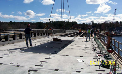
- Full-Depth Prefabricated Decks: Several different types of prefabricated decks are used, including full-depth precast concrete panels, steel grids (unfilled, filled and exodermic), fiber reinforced polymer panels, and glue laminated timber panels.
Figure 1.2.4-1 Full Depth Precast Deck Panels
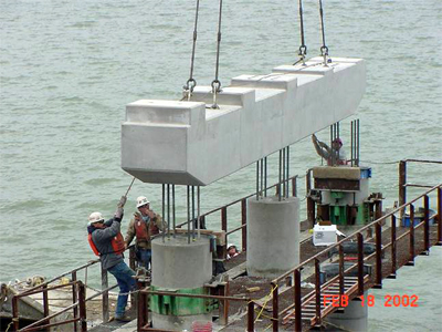
- Pier Caps: Several states use precast pier caps due to the difficulties of casting a large concrete element high in the air or over water. Precast pier caps have been used on both pile bent piers and standard concrete pier bents.
Figure 1.2.4.-2 Precast Pier Cap
In recent years, states have used more prefabricated elements to build bridges faster. These include:
- Pier columns
- Pile cap footings
- Abutment stems
- Integral abutments
- Footings
- Barriers
These elements will be discussed in more detail in the following chapters.
1.2.5 Opportunities for Architectural Treatments
An ancillary benefit of prefabrication is the opportunity to incorporate architectural features. Many prefabricated elements are made with precast concrete. Several states (Texas in particular) have taken advantage of precasting to apply significant architectural features to the prefabricated bridge elements. Figure 1.2.5-1 shows a precast pier cap constructed on a pair of cast-in-place columns. Architectural treatments typically found in building construction can also be applied to bridge projects. This gives designers significant opportunities to work with communities in the context sensitive design process to produce bridges that are preferable to the users.
Figure 1.2.5-1 Lake Belton Bridge
(Photo Courtesy of TX DOT)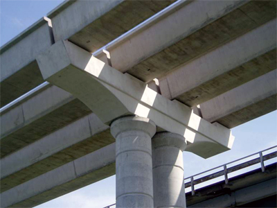
1.3 Applicability to Typical Bridges
Prefabrication and accelerated construction are not limited to large scale or signature bridges. Many states are applying this technology to ordinary bridges. Prefabrication and accelerated construction techniques can be applied to a variety of bridge projects, as discussed below:
1.3.1 New Bridges
New bridge construction offers a significant advantage when compared to rehabilitation or replacement projects in that there is often little or no conflict with traffic. These sites are often the least constricted; therefore, larger equipment can be used to move and erect the prefabricated pieces. Even if traffic control is not an issue, prefabrication and accelerated construction can be used to minimize impacts to the environment and to build a bridge faster in a harsh environment. In addition, the use of identical repeating elements, for example, precast pier caps, reduces costs.
1.3.2 Replacement of Existing Bridges
Bridge replacement projects differ from new bridge projects in that there is usually a need to maintain traffic on the roadway. In some cases, a detour can be arranged; however, detours can have a devastating impact to local communities and businesses. Prefabrication and accelerated construction can be used to reduce the time that detours are in place to minimize the impact of the project on the community.
In cases where traffic must be maintained, accelerated construction can be used to reduce the time for lane closures and diversions. It can also eliminate the need for temporary bridge structures. If a bridge can be replaced with an existing detour route combined with accelerated construction, the owner agency can save the significant costs and eliminate the environmental impact of a temporary bridge.
1.3.3 Rehabilitation of Existing Bridges
In parts of the country where there is already a mature highway network, a large portion of the assigned bridge projects involve rehabilitation of existing bridges. In many cases, this involves deck replacements, superstructure replacements, and bridge widening. Prefabrication and accelerated bridge construction techniques have proven very valuable for these types of projects, especially where lane closure limitations are severe. Many prefabricated bridge rehabilitation projects, for example, deck replacements, have been successfully completed in as little as one weekend.
1.3.4 Issues with Curved, Skewed and Flared Bridges
The complexity of the geometry of curved, severely skewed, or flared bridges combined with the lack of repetitive details makes prefabrication for these types of bridge a challenge. This does not preclude the possibility of using prefabrication for these structures, however. Prefabricated bridge deck replacement projects have been completed on bridges with significant skews and flared exit ramps, and prefabrication can be the solution of choice when widening or rehabilitating these structures over traffic. Attention to tolerances and field fit-up is essential for these complex structures.
1.3.5 Truss Bridges and Girder-Floorbeam Bridges
Truss bridges and bridges with girder-floorbeam systems offer unique challenges, but also an opportunity for prefabrication. During one successful project, the entire floor system was replaced with only overnight traffic closures. In this example, the deck on the Lewis and Clark Bridge in Washington State was replaced using a precast deck/stringer system. Figure 1.3.5-1 shows the original and the final cross-section of the bridge. The floorbeam system on the truss bridge was highly stressed in bending, but had reserve shear capacity. By varying the spacing of the stringers, the designers were able to reduce the bending moments in the floorbeams, thereby increasing the load capacity of the bridge. By using an innovative gantry crane, full-width sections were removed and replaced with full-width prefabricated sections during night closures.
Figure 1.3.5-1 Lewis & Clark Bridge
(Detail Courtesy of Washington State DOT)
(Click image to enlarge)
1.4 Typical Accelerated Construction Connection Types
During the development of this manual, information on various types of prefabricated connections were collected from across the country. The details can be categorized into several common types. These types make up the majority of connections discussed in this manual.
1.4.1 Steel Elements
1.4.1.1 Bolted
Bolted connections have been used to connect prefabricated bridge elements for many years. The process of bolting two pieces of steel together can be very fast for some connections and slow for others. Girder splices tend to be slow connections due to the large number of bolts required to make the connection.
One way to speed up construction of bolted connections is to allow a contractor the option to place only a portion of the bolts before the crane releases a particular piece. The National Steel Bridge Alliance is currently writing a steel bridge erection guide that will likely recommend that 50 percent of all bolts in each portion of a connection be installed prior to member release. This means that 50 percent of the bolts in the flanges and the webs need to be in place. By allowing a crane to release an element faster, the overall construction can proceed more rapidly.
1.4.1.2 Welded
Field welding is not as common as field bolting in most states. This is due to several factors:
- Lack of certified field welders
- Difficulties with welding in colder environments
- Concerns with the quality of field welds
- Time
Recently, several states have started to expand the use of field welding and have developed procedures that address these concerns. These new procedures show promise to increase the speed of steel element connections.
1.4.1.3 Cast-in-Place Concrete Closure Pours with Shear Studs
Several structure types make use of concrete to connect two steel elements. The idea of connecting two girders at a bridge pier shows the most promise. The concept is to design the girders as simple spans for dead load and as continuous spans for live load. This concept has been used for many years in the precast industry. The connection of two steel girders can be made by encasing the girder ends in a concrete closure pour. The live load continuity connection is transferred through the reinforced closure pour and back to the steel member via welded stud shear connectors, or bearing plates. Depending on the geometry of the closure pour, the shear studs can be placed on the girder flanges or webs.
1.4.2 Concrete Elements
1.4.2.1 Principles of Emulation Design
The America Concrete Institute has published a document entitled "Emulating Cast-in-Place Detailing in Precast Concrete Structures ACI-550.1 R01" [4]. The goal of emulation design is to achieve performance of a prefabricated system that is comparable to a cast-inplace system. For emulation design in seismic regions, the goal is for a prefabricated system to be comparable to a cast-in-place system in performance such as energy dissipation, ductility, stiffness, strength, and similar reliable failure modes. Cast-in-place concrete structures are built with construction joints that usually involve lapped reinforcing bars. The principal of emulation design is to substitute an alternate connection that mimics or "emulates" the standard lap splice. This approach has been developed primarily by the precast parking garage and hotel industry. By using emulation, a bridge designer or contractor can substitute precast concrete elements for traditional cast-in-place elements.
ACI-550.1 goes into great detail on different connections; therefore, the authors suggest referring to this document. The following sections outline some of the most common emulation connections:
Grouted Reinforcing Splice Couplers
Several manufacturers have developed couplers that can splice large diameter reinforcing steel bars within precast elements. These couplers are typically hollow cast steel sleeves (similar to a pipe). The sleeve is cast into the end of one element and a protruding reinforcing bar is cast in the end of the adjacent element. The elements are connected by inserting the protruding bars from one element into the hollow end of the coupler in the other element. The joint between the pieces is then grouted, and grout is pumped into the couplers to make the connection.
Casting tolerances are important with these couplers; however, the precast industry has demonstrated on many projects that the required tolerances are achievable on plant produced precast products.
Large diameter bars can be spliced in distances that are much less than conventional development lengths; an attribute which makes this connection desirable for substructure connections with large bars (pier caps, columns, etc.). These connections can be made quickly in tight confines. It is reasonable to obtain a full moment connection in as little as 12 hours. Temporary struts can be used to allow erection of the elements prior to grouting.
Sleeved connections are most often used in the vertical direction. They can be used in the horizontal direction, but this can complicate the erection procedure because of the difficulty of rigging a large element with small tolerances.
These connections have been thoroughly tested and can develop up to 125%, 150% and even 160% of the specified yield strength of the reinforcing bars.
Grouted Post-Tensioning (PT) Ducts
Several states have experimented with the use of PT ducts for connections between precast concrete elements. These connections are similar to grouted reinforcing splice couplers in that reinforcing bars or threaded rods are inserted into a sleeve made up of standard post-tensioning duct. The difference is that the duct is non-structural; therefore, additional confinement reinforcing is required around the pipe to develop a significant connection. The PT duct is much larger than a grouted coupler; therefore, tolerances are not as strict. Research to date has demonstrated that significant moments can be achieved with this system; however, the system is currently not recommended for high seismic areas that require plastic hinging of connections. These connections have not demonstrated the required ductility required in high seismic zones.
Grouted Voids
Like PT ducts, these connections are similar to grouted splice couplers except the coupler is simply replaced with a void cast in the receiving element. These connections typically have been used on connections that are considered pin connections that will transfer little or no moment between the elements.
Traditional Post-tensioning (PT)
PT connections have been used between precast concrete elements for years. The most common type of PT connection is between pieces in a segmental box girder bridge. Several states have also used PT for connections in pier columns and pier caps. Another common use of PT is in precast concrete bridge decks. Many states have used PT combined with grouted shear keys to connect deck elements (typically the PT is run in the longitudinal direction on typical stringer bridges). The PT systems often used include multiple grouted strands in ducts and grouted high strength thread bars.
Welded Connections
Precast elements can be connected using welding. This process is common in the building and parking garage industry. Steel plates are embedded in the precast elements and a welded connection is made after erection. Several states have developed and researched welded connections for precast butted beam systems such as slabs, double tees and even deck bulb tee girders.
Bolted Connections
Bolting of precast elements is rare, due to the difficulties of working with the tight tolerances required for quality bolting. Several states have used bolting to connect steel diaphragms on parallel precast stringer bridges; however, differential camber between members can make this connection difficult. Another use of bolting is to connect precast concrete parapet elements. Several states have used bolts that are drilled and grouted into the bridge deck to secure the precast parapet to the deck. Designers should check with each state regarding these connections; some have not been crash tested and approved for used on the national highway system.
Cast-in-place Concrete Closure Pours
One of the simplest connections that can be made between two precast concrete elements is to leave a small area between the elements to allow for a closure pour of cast-in-place concrete. This is often done on horizontal connections that make sleeved connections difficult to achieve. The connection is usually made using simple lap splices.
1.5 Seismic Considerations
During seismic events, connections between bridge elements must resist the highest force demand and cyclic effects. This section discusses current criteria for seismic details, and provides information on current and proposed research.
1.5.1 General Criteria
The design and detailing of elements and connections in a prefabricated bridge for seismic forces generally needs to be similar to designs and details in non-prefabricated bridges. All provisions specified in AASHTO LRFD Bridge Design Specification [1] need to be satisfied in any bridge. This includes, but is not limited to, reinforcing steel in footings, plastic hinge zones, column confinement, and connections between the superstructure and substructure. There is on-going research into alternate connection designs for high seismic regions [5]
1.5.2 Connection of Superstructure to Substructure
There are several methods of connecting normal stringer bridges to the substructures. In most cases, these connections are designed to transmit lateral seismic forces from the superstructure to the substructure. It is also possible to make the connection integral.
Pinned Connections
In most states, the connection of the superstructure to the substructure is detailed as a pinned connection. Integral connections are also specified, but are not as common. The most common type of pinned connection is through the bearing device. The forces are transmitted from the superstructure, through the bearing and then into the substructure. Often this is accomplished using anchor rods. However, the current AASHTO design specifications do not address the resistance of embedded anchor rods in concrete. A pending revision to the AASHTO specifications will include a reference to the American Concrete Institute Building Code Requirements for Structural Concrete (ACI 318), Appendix D [6]. This ACI code addresses the issue of resistance of imbedded anchor rods in great detail.
Another means to provide lateral restraint is to install keeper assemblies adjacent to beams. Keeper assemblies usually consist of concrete keys placed between two interior beams to transmit lateral forces from the superstructure to the substructure. The assemblies are usually cast after the beams have been erected; therefore, tolerances are not a significant issue. Longitudinal seismic forces can be resisted by the abutment backwall. Keeper assemblies are often the most cost effective means of restraining a bridge for seismic events in low seismic zones. They are especially desirable on skewed concrete pier bents where the tight confines of reinforcing steel make installation of anchor rods very difficult (if not impossible). The location of the reinforcing steel in the keeper assemblies is not as critical as an anchor rod; therefore they can be easily adjusted to fit the field conditions. Figure 1.5.2-1 shows a typical keeper assembly used in the northeast states.
Figure 1.5.2-1 Concrete Keeper Assembly
There are other options for seismic restraint such as cable restrainers and seismic isolation devices. These methods are also acceptable; however, they are not commonplace and are therefore not included in this Manual.
Moment Connections
Moment connections between substructures and superstructures are used to provide additional stability to the structure during seismic events and to eliminate bridge deck joints. These connections can also reduce lateral displacements of the structure and reduce forces in the foundations. Integral pier connections and integral abutment connections are common in high seismic regions. This requires high moment demand on the connections. The most common type of connection between prefabricated elements is a cast-in-place closure pour. There is concern in the Figure 1.5.2-1 Concrete Keeper Assembly industry that grouted reinforcing splice couplers and grouted PT ducts are not capable of developing plastic hinges in these high demand connections; therefore their use has been limited. It is anticipated that future research will address these concerns. See Section 1.5.4 for more discussion on this topic.
1.5.3 Superstructure Connections
In conventional stringer bridges having no integral connection between the superstructure and substructure, there is relatively low force demand on superstructure elements. The superstructure does see seismic forces; however, the majority of the seismic induced forces are found in the substructure. If the superstructure is integrally connected to the substructure, large seismic forces can be transmitted to the superstructure. In this scenario, engineers must take care in designing connections between prefabricated bridge superstructure elements in addition to connections in substructure elements, including superstructure design for overstrength conditions.
1.5.4 Columns and Column Connections
Columns are often the most heavily loaded elements during a seismic event. Special care must be taken to properly detail connections in precast concrete column elements. In high seismic regions, columns are designed to form plastic hinges and contribute to dissipation of seismic forces. The high demand region on a typical column is at the ends where the column connects to the footings and pier caps.
Semi-ductile moment connections can be made in precast elements by using grouted reinforcing splice couplers for longitudinal reinforcing steel confined by transverse reinforcing steel. Research from Japan has shown that the grouted reinforcing splice couplers can fully develop the longitudinal reinforcing bars as well as contribute to shifting the plastic hinge away from the extreme end of the column [7].
Grout filled reinforcing splice couplers are capable of developing 125% reinforcing steel yield strength. Some states require at least 150% of the specified steel yield strength of the bar be developed for splices in plastic hinge zones. Some grout filled reinforcing splice couplers and grouted post-tensioning duct can also achieve this level of strength.
The AASHTO specifications allow for splicing 100% of the longitudinal bars with mechanical splices at one location for low to moderate seismic zones. Low seismic zones are defined Zones 1 and 2 in the LRFD Specifications [1]. For higher seismic categories and zones, the codes require staggering every other bar by a distance of 24 inches (Section 5.10.11.4.1f of the LRFD Specifications [1]). A grout filled reinforcing splice coupler behaves differently than a lap splice. The strength of the splice is not dependent on the concrete surrounding the sleeves. Therefore, limitations for locations of lap splices caused by lack of cover concrete in the hinge zones in theory should not be applicable to mechanical connectors. There are ongoing discussions within the industry on this topic, and future research may explore this issue.
There is one way to meet the AASHTO requirements using grouted reinforcing splice couplers. The designer can detail one-half of the sleeves on one side of the connection and one-half of the sleeves on the other side of the connection. Another way to accomplish this is to place the mechanical connectors within the footing where loss of confinement is not a factor; however, locating the connectors in a pier cap connection may still be an issue due to possibility of loss of cover on the side faces of the pier cap.
Confinement Reinforcement
Some designers believe that the only way to confine column reinforcing is to use spiral confinement reinforcing that passes into the footing or pier cap, making precast columns impractical. This, however, is not the case. AASHTO provisions for confinement based on cast-in-place concrete construction should be followed.
Longitudinal bars can be confined with transverse ties detailed in accordance with the AASHTO specifications. Transverse ties can be used in place of spiral stirrups as long as they are properly detailed to achieve confinement. The AASHTO LRFD Specifications [1] states:
"Column transverse reinforcement, as specified in Article 5.10.11.4.1d, shall be continued for a distance not less than one-half the maximum column dimension or 15.0 in. from the face of the column connection into the adjoining member."
Section 5.10.2.2 states:
"Seismic hooks shall consist of a 135°-bend, plus an extension of not less than the larger of 6.0 db or 3.0 in. Seismic hooks shall be used for transverse reinforcement in regions of expected plastic hinges. Such hooks and their required locations shall be detailed in the contract documents."
These provisions do not require the confinement steel to pass through the joint between the column and pier cap or footing. Therefore, it is acceptable to properly terminate the transverse tie confinement steel at the end of the precast column, and also in the adjoining member by using ties in place of spiral reinforcement. The AASHTO Subcommittee on Bridges and Structures continues to look into these issues; therefore, users of this Manual should refer to the AASHTO specifications for the latest requirements.
1.5.5 Footings
The design of precast footings for seismic forces should follow normal procedures for cast-in-place concrete footings. Requirements must be met for confinement of column dowels.
1.5.6 Deep Foundations
If precast pile caps are used, special details may be required to provide Page 1-16 Chapter 1: General Topics pile uplift and moment capacity in precast footings. Several states have developed details for footing connections that consist of extending the pile reinforcing into a concrete closure pour pocket. Several conceptual methods for connecting a precast footing to steel or precast piles have also been developed by the Northeast Regional PCI Bridge Technical committee and are included in data sheets in this manual.
Several states have used prefabricated concrete panels to form a cofferdam on top of precast piles and drilled shafts. These cofferdams eliminate the need for deep sheeting and dewatering that have been commonly used for years. The prefabricated panels form a pier box that when used in conjunction with a tremie concrete pour provide a platform and area in which to cast the pier footing and connect it to the drilled shaft or pile below.
1.5.7 Research
There is ongoing research into connections between prefabricated elements in high seismic zones, including column and cap-to-column connections using various types of connectors. Designers should refer to the results of these research projects for guidance.
| << Previous | Contents | Next >> |