

Manual on Use of Self-Propelled Modular Transporters to Remove and Replace Bridges
Chapter 1. Introduction
1.1. Background
The use of self-propelled modular transporters (SPMTs) for bridge moves was the top implementation recommendation of the 2004 Prefabricated Bridge Elements and Systems International Scan sponsored by the Federal Highway Administration (FHWA), the American Association of State Highway and Transportation Officials (AASHTO), and the Transportation Research Board's National Cooperative Highway Research Program.(1,2) The purpose of the scan was to learn how other countries use prefabricated bridge components to minimize traffic disruption, improve work zone safety, reduce environmental impact, improve constructability, enhance quality, and lower life-cycle costs.
Prefabrication of bridges offsite under more controlled conditions followed by rapid installation onsite can achieve quality installations in significantly less time than the months or years typically required for conventional bridge construction. The use of SPMTs in combination with prefabrication should be considered for all bridge replacement projects in locations with high traffic volumes, such as those with 40,000 or more vehicles per day either on the bridge or on the roadway below the bridge. Other factors mentioned above may also make the use of SPMTs the best choice for the project.
The sequential processes of conventional onsite bridge superstructure construction include the following:
- Erecting beams
- Erecting stay-in-place or temporary deck forms and overhang forms
- Installing shear studs on steel girders
- Tying deck reinforcement
- Placing deck concrete
- Curing deck concrete
- Removing temporary formwork
- Placing barriers and appurtenances such as light poles, screens, and signs
With SPMT technology, the conventional sequence is reduced to one step: Move the prefabricated bridge superstructure to its final position.
The significant construction time savings from using SPMTs to install prefabricated bridges are due to the change from the sequential processes of conventional bridge construction to concurrent processes, followed by the use of SPMTs to quickly install the bridge:
- Prefabrication can begin well before site preparation has been completed. A replacement bridge can be built at a nearby staging area that does not impact the traveling public, at a lower elevation for improved construction safety, and on a timeline that allows attention to details such as proper concrete deck curing to achieve good long-term performance.
- The demolition process is significantly improved. It is not necessary to construct shielding to protect traffic under the bridge, saving time and money and reducing the need for road closure. Danger to traffic below from debris falling off or through the shielding is eliminated. Quick removal of the existing bridge using SPMTs followed by demolition at a staging area speed onsite construction compared to the incremental onsite demolition of conventional construction projects. SPMTs may be used for removal only on a project, or to both remove the existing bridge and install the new bridge.
- The prefabricated bridge can be ready to install as soon as the site has been prepared. SPMTs can move the new bridge superstructure or complete bridge into place in minutes, with construction inspection completed and traffic flow restored within several hours.
SPMTs can also move multispan superstructures and bridges complete with substructures, further reducing onsite construction time. Both concrete bridges and steel bridges can be moved with SPMTs.
1.2. Description of Equipment
SPMTs are computer-controlled platform vehicles used extensively in Europe to lift and drive components of the petrochemical, offshore, power, and heavy civil engineering industries. The shipbuilding industry uses SPMTs to move ship components during fabrication and the transportation industry uses them to move bridges. SPMTs move bridge systems weighing from 165 to 3,600 tons (149.6 to 3,265.8 metric tons) with precision to within a fraction of an inch.
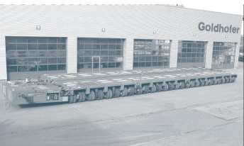
A single SPMT unit has either six- or four-axle lines, with each axle line consisting of multiple wheels arranged in pairs and spaced at a maximum 5 feet (ft) (1.5 meters (m)). Six-axle units are shown in figures 1(a) and 1(b). The units can be rigidly coupled longitudinally and laterally to combine several units, as shown in figure 1(c), for synchronized movement of all axles. The units are connected by a cable and controlled by one driver who operates the controller while walking with the units. If the computer malfunctions, the SPMTs under each span end can still operate, but with operators manually coordinating to ensure their numbers are the same. Two operators are also used when a span is being set because the span ends are set independently.
Figure 1: (a) SPMT six-axle unit, 8 ft (2.4 m) wide
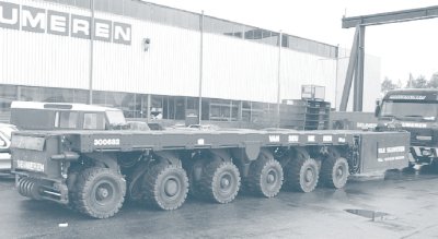
Figure 1: (b) SPMT six-axle unit, 10 ft (3 m) wide
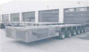
Figure 1: (c) SPMT units coupled longitudinally and laterally
The term "SPMT" is somewhat generic in the market, and there are self-driven units limited to only 60 degrees. This manual, however, concerns SPMTs with electronic steering capability that allows 360-degree pivoting about a point. The controller has four basic commands: steer, lift, drive, and brake. The computerized electronic steering capability allows movement in any horizontal direction: straight forward and backward, transversely, diagonally, and at any angle as well as carousel steering. Each pair of wheels can pivot 360 degrees about its support point. Loaded SPMTs typically travel at a walking pace of 3 miles per hour (mi/h) (4.8 kilometers per hour (km/h)) or 4.4 feet per second (ft/s) (1.3 meters per second (m/s)) and can travel up to 7 mi/h (11.2 km/h) or 10 ft/s (3 m/s), depending on load and terrain.
A four-axle SPMT unit is about 20 ft (6 m) long without the powerpack unit; a six-axle unit is about 30 ft (9.1 m) long without the powerpack unit. The powerpack unit adds another 13 to 14 ft (3.9 to 4.2 m) to the length of each unit. SPMTs can be transported to the bridge site on normal flatbed trailers or shipped in flat rack containers. For highway transport, the six-axle units require overweight permits and the 10-ft (3-m) wide units require permits for both width and weight.
Each SPMT unit is 8 ft (2.4 m) wide with four wheels per axle line or 10 ft (3 m) wide with eight wheels per axle line. Capacity and lift range vary by manufacturer, configuration type (e.g., unit width), and ground conditions.
The top surface of the unloaded SPMT platform at its lowest position is at most 4 ft (1.2 m) from the ground surface. Factors such as magnitude of load, tire compression, platform camber, and ground surface variation along the travel path affect the loaded SPMT platform travel height. The preferred minimum platform travel height is 44 to 60 inches (in) (111.7 to 152.4 centimeters (cm)), but the platform height may be as low as 36 to 50 in (91.4 to 127 cm) during travel.
The minimum available vertical stroke of the SPMT platform is about 24 in (60.9 cm), and the vertical lift range is about 36 to 60 in (91.4 to 152.4 cm). An available vertical stroke of 16 to 20 in (40.6 to 50.8 cm) should be assumed for operational purposes.
The SPMT platform can be vertically adjusted up to 24 in (60.9 cm) to keep the load horizontal without distortion while traversing uneven and sloping ground surfaces. SPMTs can travel on uneven terrain with surface variations up to 18 in (45.7 cm) and on grades up to 8 percent, depending on ground surface friction. Equipment for vertical lifting can be mounted on the SPMT platform as needed. Equal loads are maintained on each axle line through the SPMT's three-point or four-point hydraulic suspension system, which consists of two hydraulic rams per axle line with each ram attached to a hinged elbow supported by two wheels. If the ground settles during a bridge move, the hydraulic system compensates for the height difference.
A set of SPMT units under a lift point can be connected transversely to a set of SPMT units under a second lift point through the installation of connecting cross-frames. This may be required to minimize differential movement between the points.
Each axle line has a maximum applied-load capacity of 26 to 33 tons (24 to 30 metric tons), depending on unit width, and exerts a maximum ground pressure of 1,500 to 2,000 pounds per square foot (7,323.6 to 9,764.8 kilogram-force per square meter), depending on magnitude of load. The maximum load per axle line is not always possible, however, because the heavy loads being transported can create excessively high ground bearing pressures. In such cases, additional SPMT units may be required to reduce the bearing pressure to an allowable level. Steel plates can also be placed along the travel path to help spread the loads. The maximum load per axle line may also not be possible when loads have a high centroid of gravity. In such cases, additional SPMT units may be required if cross-frames connecting the units are not sufficient to ensure stability.
The SPMTs will have blocking on top of their platforms to support all the beams in the span. For bridge removals, the SPMT units will be assembled, blocking will be placed on top of the SPMT platforms, the SPMTs will drive under the span and lift it using their hydraulic system, the loaded SPMTs will travel at a normal walking pace to the staging area, and the SPMTs will incrementally lower the span onto temporary blocking for demolition. A similar process in the reverse order is used to move a new bridge into place.
1.3. Equipment Availability and Services
As part of the 2004 scan, the scan team visited two SPMT companies. These worldwide specialists in heavy and complex lifting and transport are Mammoet, a member of the Van Seumeren Group headquartered in the Netherlands (www.mammoet.com), and the Sarens Group, headquartered in Belgium (www.sarens.com). SPMTs are part of the extensive equipment inventory of both companies. Mammoet has 2,200 axle lines of SPMTs; Sarens has 500 axle lines. The approximate cost of one axle line is $150,000.
Mammoet has offices in the United States and has done most of the U.S. bridge moves. Sarens has operations in the United States and has recently entered the U.S. bridge market. Barnhart Crane & Rigging Company (http://barnhartcrane.com), a U.S. company with offices in a number of States, has recently purchased 108 SPMT units and has expressed significant interest in the U.S. bridge market. Other U.S. companies that own and operate SPMTs include S.G. Marino Crane Service Corporation (http://www.marinocrane.com), headquartered in Middletown, CT, and Bigge Crane & Rigging Co. (http://www.bigge.com), headquartered in San Leandro, CA. For large moves, these companies may lease SPMTs from each other to reduce the cost of the move. By doing this, each company does not need to own large quantities of machinery that lay idle. The more the industry maximizes the use of the equipment, the lower the net cost.
These SPMT companies are more than equipment suppliers. They have engineering departments that develop detailed moving plans. In bridge projects in the United States to date, the SPMT company typically has been a subcontractor to the general contractor that is awarded the project. On larger or more complex projects, the SPMT company is typically a subcontractor to the bridge subcontractor to the general contractor that is awarded the project.
The SPMT company handles the details of the actual move, including engineering, site surveys, crew and equipment scheduling, equipment assembly operations, transport route, and logistics plans that minimize traffic disruption.
An example of the engineering services SPMT companies provide is the design and engineering of temporary supports for the move. The companies have various systems to lift and support the loads before and during the move. For example, Mammoet has its Titan Bridge Lift System (see figure 2(a)), climbing jack system (see figure 2(b)), and container support system (see figure 2(c)). A strand jack system may be used for larger, taller moves (see figure 2(d)). The engineering services of these companies include determining which system is best considering mobilization cost and weight and height of the load.
Figure 2: (a) Titan Bridge Lift System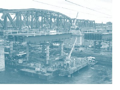
Figure 2: (b) Climbing jack system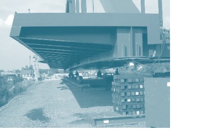
Figure 2: (c) Container support system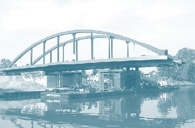
Figure 2: (d) Strand jack system
Mammoet's Titan Bridge Lift System was designed to install large prefabricated bridge spans, remove old bridges, and realign existing bridges by moving them horizontally or vertically. The lifting system is composed of modular steel "stools," each ranging in height from 16 in (40.6 cm) to 4 ft (1.2 m). The stools sit atop the SPMT platform. The SPMT hydraulic suspension system provides the lifting force for the Titan towers, and the stools are inserted incrementally. The process is repeated until the bridge is at the desired height.
Another example of the SPMT companies' engineering services is the design and engineering of temporary substructures used to support superstructures at their staging area before they are moved to their final locations. The Sarens Group has designed a standardized system of temporary substructures that are adaptable for their various bridge projects. An example of Sarens' standardized temporary substructure is shown in figure 3.
Figure 3: Substructure for temporary bridge support for Nootdorp Bridge in the Netherlands
SPMT companies can also provide special framing systems to use in conjunction with SPMTs to address the needs of the bridge move. For example, for the Washington State Department of Transportation (WSDOT) Lewis and Clark Bridge deck replacement project (see 7.1.5 in "Case Studies"), Mammoet developed a special framing system to carry the full-width, full-depth deck panels. Another example is Barnhart's gantry system that can be used with SPMTs to remove and replace bridge spans over roadways or rail lines while providing minimal interruption to service.
1.4. List of Example Calculations, Diagrams, Plan Sheets, and Specifications
A number of example calculations, diagrams, plan sheet details, and specifications are included in this manual to use as a starting point for projects using SPMTs to move bridges. Below is a list of those examples, in the order of their location in the text.
3.2.2 Contracting Strategies and Delay-Related User Costs
- An example user cost spreadsheet is in Appendix A.
4.4.1 Decks
- Example plan sheet details for a cast-in-place deck closure pour option to facilitate span fit-up are in Appendix B.
4.9.1.2 Use of Lightweight Aggregate
- Example calculations for comparing the total bridge weight and estimated cost premium for a bridge with normal-weight concrete and lightweight concrete are in Appendix C.
6.1 SPMT Equipment Requirements
- An example specification for SPMT equipment is in Appendix D.
6.2 Alternative Bridge Installation With SPMTs
- Wording for an alternative bridge installation method using SPMTs is on the example contractor alternatives plan sheet in Appendix E.
6.3 Alternative Superstructure Design to Reduce Dead Load
- Wording for an alternative composite dead load bridge design to be used in conjunction with SPMTs is on the example contractor alternatives plan sheet in Appendix E.
- An example of wording for the lightweight concrete option that can be added to the contractor alternatives plan sheet in Appendix E is as follows:
- Lightweight concrete may be used for any or all superstructure elements.
- Lightweight concrete shall conform to the Standard Specifications.
- An example specification for lightweight concrete is in Appendix F.
6.4.1 Incentive/Disincentive
- An example incentive/disincentive specification used in conjunction with the contractor alternatives plan sheet in Appendix E is in Appendix G.
- Examples of other boilerplate incentive/disincentive specifications are in Appendix H.
6.4.2 Bonus
- An example bonus specification used in conjunction with the contractor alternatives plan sheet in Appendix E is in Appendix G.
- Examples of other boilerplate bonus specifications are in Appendix I.
6.4.3 Lane Rental
- Examples of lane rental specifications are in Appendix J.
6.5 Value Engineering
- An example value engineering specification is in Appendix K.
6.6 Partnering
- An example partnering specification is in Appendix L.
6.7 Traffic Control Plans
- An example listing of general notes for traffic control are in Appendix M, with the two modifications for SPMT methods shown in bold.
- An example traffic control plan sheet for rolling roadblocks used for conventional bridge demolition is in Appendix M (see "I-4 Pacing Operation General Notes"). Only one rolling roadblock is required when SPMTs are used to remove an entire span, instead of conventional demolition in which a rolling roadblock is required for each beam removal.
- An example traffic control plan for a temporary bridge closure when SPMTs were used to replace spans of a bridge crossing a highway is in Appendix M (see "I-4 Closure Detail").
6.8.1 Temporary Shoring Bents Founded on Shallow Foundations- Differential Settlement
- An example specification for a temporary shoring on shallow foundations settlement report is in Appendix N.
6.9 Movement Plan
- Examples of path and motion diagrams are in Appendix O.