U.S. Department of Transportation
Federal Highway Administration
1200 New Jersey Avenue, SE
Washington, DC 20590
202-366-4000
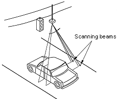
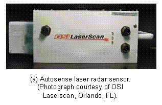
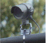
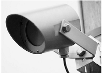
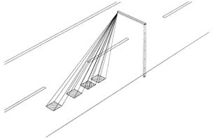
A Summary of Vehicle Detection and Surveillance Technologies use in Intelligent Transportation SystemsChapter 5 - Over-roadway Sensor Technologies (cont)Infrared SensorsActive and passive infrared sensors are manufactured for traffic applications. The sensors are mounted overhead to view approaching or departing traffic or traffic from a side-looking configuration. Infrared sensors are used for signal control; volume, speed, and class measurement, as well as detecting pedestrians in crosswalks. With infrared sensors, the word detector is also used to refer to the light-sensitive element that converts the reflected or emitted energy into electrical signals. Real-time signal processing is used to analyze the received signals for the presence of a vehicle. Active Infrared SensorPrinciples of OperationActive infrared sensors illuminate detection zones with low power infrared energy supplied by laser diodes operating in the near infrared region of the electromagnetic spectrum at 0.85 mm. The infrared energy reflected from vehicles traveling through the detection zone is focused by an optical system onto an infrared-sensitive material mounted at the focal plane of the optics. The active infrared laser sensor has two sets of optics. The transmitting optics split the pulsed laser diode output into two beams separated by several degrees as displayed in Figure 29. The receiving optics has a wider field of view so that it can better receive the energy scattered from the vehicles. By transmitting two or more beams, the laser radars measure vehicle speed by recording the times at which the vehicle enters the detection area of each beam Application and UsesActive infrared sensors provide vehicle presence at traffic signals, volume, speed measurement, length assessment, queue measurement, and classification. Multiple units can be installed at the same intersection without interference from transmitted or received signals. Modern laser sensors produce two- and three-dimensional images of vehicles suitable for vehicle classification. The laser radar illustrated in Figure 30a mounts 19.7 to 23 ft (6 to 7 m) above the road surface with an incidence angle (i.e., forward tilt) of 5 deg. Its ability to classify 11 types of vehicles has found use on toll roads. Other models from this manufacturer mount between 5 and 16 ft (1.5 and 4.9 m) from the edge of the traffic lane above the road and classify vehicles based on the number of axles detected. Another laser radar with similar capabilities is shown in Figure 30b. This device can transmit 2 to 6 beams, which control the length of the scan over the travel lane.
Figure 29. Laser radar beam geometry. (Drawing courtesy of OSI Laserscan, Orlando , FL ).
Figure 30. Laser radar sensors. Passive Infrared SensorsPassive sensors detect the energy that is emitted from vehicles, road surfaces, other objects in their field of view, and from the atmosphere, but they transmit no energy of their own. Non-imaging passive infrared sensors used in traffic management applications contain one or several (typically not more than five) energy-sensitive detector elements on the focal plane that gather energy from the entire scene. The detector in a non-imaging sensor generally has a large instantaneous field of view. The instantaneous field of view is equal to the angle, e.g., in the x-y plane, subtended by a pixel. Objects within the scene cannot be further divided into sub-objects or pixels (picture elements) with this device. Imaging sensors, such as modern charge-coupled device (CCD) cameras, contain two-dimensional arrays of detectors, each detector having a small instantaneous field of view. The two-dimensional array gathers energy from the scene over an area corresponding to the field of view of the entire array. Imaging sensors display the pixel-resolution details found in the imaged area. Principles of Operation Passive infrared sensors with a single-detection zone, measure volume, lane occupancy, and passage. The source of the energy detected by passive sensors is graybody emission due to the non-zero surface temperature of emissive objects. Graybody emission occurs at all frequencies by objects not at absolute zero (-273.15oC). If the emissivity of the object is perfect, i.e., emissivity = 1, the object is called a blackbody. Most objects have emissivities less than 1 and, hence, are termed graybodies. Passive sensors can be designed to receive emitted energy at any frequency. Cost considerations make the infrared band a good choice for vehicle sensors with a limited number of pixels. Some models operate in the long-wavelength infrared band from 8 to 14 mm and, thus, minimize the effects of sun glint and changing light intensity from cloud movement. Several passive infrared sensors are illustrated in Figure 31. The Eltec 842 sensor is used for vehicle presence detection at signalized intersections for side street demand, at construction sites, and for temporary replacement of failed inductive loop detectors. The Siemens Eagle PIR-1 sensor performs vehicle counting, stopline presence detection, occupancy detection, and queue detection. The ASIM IR 250 series are multizone sensors that offer vehicle counting, speed measurement, classification by length, and presence detection.
Eltec 842 passive infrared vehicle presence sensor [Photograph courtesy of L.A. Klein, Sensor Technologies and Data Requirements for ITS ( Norwood , MA : Artech House, 2001)]
ASIM IR 250 series passive infrared sensor (Photograph courtesy of ASIM Technologies, Uznach , Switzerland ) Figure 31. Passive infrared sensors. When a vehicle enters the sensor's field of view, the change in emitted energy is used to detect the vehicle as illustrated in Figure 32. A vehicle entering the sensor's field of view generates a signal that is proportional to the product of an emissivity difference term and a temperature difference term when the surface temperatures of the vehicle and road are equal. The emissivity term is equal to the difference between the road and the vehicle emissivities. The temperature term is equal to the difference between the absolute temperature of the road surface and the temperature contributed by atmospheric, cosmic, and galactic emission. On overcast, high humidity, and rainy days, the sky temperature is larger than on clear days and the signal produced by a passing vehicle decreases. This, in itself, may not pose a problem to a properly designed passive infrared sensor operating at the longer wavelengths of the infrared spectrum, especially at the relatively short operating ranges typical of traffic management applications ( Klein , 2001). 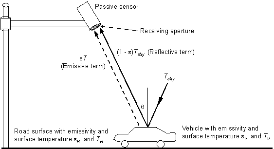
Figure 32. Emission and reflection of energy by vehicle and road surface. Application and Uses Multi-channel and multi-zone passive infrared sensors measure speed and vehicle length as well as the more conventional volume and lane occupancy. These models are designed with dynamic and static-thermal energy detection zones that provide the functionality of two inductive loops. Their footprint configuration is shown in Figure 33. The time delays between the signals from the three dynamic zones are used to measure speed. The vehicle presence time from the fourth zone gives the occupancy of stationary and moving vehicles.
Figure 33. Multiple detection zone configuration in a passive infrared sensor. AdvantagesInstallation of infrared sensors does not require an invasive pavement procedure. Some advantages of active infrared sensors are that they transmit multiple beams for accurate measurement of vehicle position, speed, and class. Also, multi-zone passive infrared sensors measure speed. Multiple lane presence detection is available in side-mounted models. DisadvantagesSeveral disadvantages of infrared sensors are sometimes cited. Glint from sunlight may cause unwanted and confusing signals. Atmospheric particulates and inclement weather can scatter or absorb energy that would otherwise reach the focal plane. The scattering and absorption effects are sensitive to water concentrations in fog, haze, rain, and snow as well as to other obscurants such as smoke and dust. At the relatively short operating ranges encountered by infrared sensors in traffic management applications, these concerns may not be significant. However, some performance degradation in rain, freezing rain, and snow has been reported (Kranig, et al., 1997). A rule of thumb for gauging when an infrared sensor may experience difficulty detecting a vehicle in inclement weather is to note if a human observer can see the vehicle under the same circumstances. If the observer can see the vehicle, there is a high probability the infrared sensor will detect the vehicle. MANUFACTURER AND VENDOR INFORMATION Effective Date: 6/15/07 Manufacturer name: Sales representative name(s): OSI LaserScan Address: 300 Sunport Lane, Ste. 500 Address: Orlando , FL 32809 Phone number: (407) 581-6000 Phone number: Fax number: (407) 581-6038 Fax number: e-mail address: sales@osi-ls.com e-mail address: URL address: http://www.osi-ls.com URL address: PRODUCT NAME/MODEL NUMBER: AutoSense 600 Overhead Vehicle Detection and Classification Sensor FIRMWARE VERSION/CHIP NO.: SOFTWARE VERSION NO.: N.A. GENERAL DESCRIPTION OF EQUIPMENT: The AS600 Series AutoSense™ vehicle detection and classification sensor is a class I laser system that provides toll and traffic management authorities with vehicle detection, presence, separation and classification information. A single sensor can be mounted above a travel lane on either a gantry, pole arm or toll plaza roof structure. The AutoSense™ scans the roadway beneath the sensor, taking range measurements across the width of the road at two locations beneath the sensor. These measurements are processed to generate messages that uniquely detect and classify each vehicle, and give its speed and position in the lane. The AutoSense™ automatically initializes the vehicle detection process upon power-up and its self-calibration process eliminates the need for any field adjustments. SENSOR TECHNOLOGY AND CONFIGURATION: Scanning infrared laser - Two beams with 10 degree separation. Each beam scans 30 degrees across lane. SENSOR INSTALLATION: Typically mounted between 19.7 and 23 ft (6 and 7 m) centered above the traffic lane. The first beam look-down angle is 10 degrees off nadir and the second beam's look-down angle is nadir (0 degrees). These beam angles are realized by mounting the sensor with a 5-degree forward tilt. INSTALLATION TIME (Per Lane ): Approximately 20 minutes INSTALLATION REQUIREMENTS: Requires AutoSense™ mounting plate, power cable and signal cable. MAXIMUM NUMBER OF LANES MONITORED SIMULTANEOUSLY: One PRODUCT CAPABILITIES/FUNCTIONS:
RECOMMENDED APPLICATIONS: Electronic toll collection, traffic data studies, flow measurement, traffic monitoring. POWER REQUIREMENTS (watts/amps): 90-140 V, 50-60 Hz, 1.5 A or 200-264 V, 50-60 Hz, 1.0 A; Power consumption 35 W nominal, 157 W maximum (motor startup and heaters on). POWER OPTIONS: See above. CLASSIFICATION ALGORITHMS: FHWA 13 Scheme F or customer specified TELEMETRY: COMPUTER REQUIREMENTS: 166 MHz, 486 or better DATA OUTPUT: RS-422 (RS-232 optional) serial interface at 19.2, 38.4 or 57.6 K baud to a 10-pin communication connector that attaches to the communication cable. This interface provides data messages in normal mode. AutoSense™ also has a high-speed (1.25 Mbps) RS-422 interface capability. The high-speed interface is used in applications requiring transmission of the sensor's raw range and intensity data. DATA OUTPUT FORMATS: Binary data files SUPPORTING DATA BASE MANAGEMENT SYSTEM: N/A EQUIPMENT AND INSTALLATION COSTS (One-lane and four-lane): STATES CURRENTLY USING THIS EQUIPMENT: Country/State Contact name Telephone number USA/Illinois Bruce Hedlund 603) 505-8266 USA / New York Jim Tate (518) 471-4349 USA/Florida Peter Zadarlik (407) 481-9994 Canada/Ontario A.J. Mohenred (905) 265-1733 USA/Florida Doug Martin (805) 488-5687 USA/Colorado Amos Pace (609) 235-5252 USA / New York Joe Lipari (732) 287-8585 USA/California Sialele Malope (658) 646-4200 South Korea Yang-Jong Park 011-02-531-8704 Italy Stefano Zoppi 011-39-55-420-2322 MANUFACTURER AND VENDOR INFORMATION Effective Date: 6/15/07 Manufacturer name: Sales representative name(s): OSI LaserScan Address: 300 Sunport Lane, Ste. 500 Address: Orlando , FL 32809 Phone number: (407) 581-6000 Phone number: Fax number: (407) 581-6038 Fax number: e-mail address: sales@osi-ls.com e-mail address: URL address: http://www.osi-ls.com URL address: PRODUCT NAME/MODEL NUMBER: AutoSense 700 Axle-Based Vehicle Detection and Classification Sensor FIRMWARE VERSION/CHIP NO.: SOFTWARE VERSION NO.: A command is available to request firmware version information from the sensor. GENERAL DESCRIPTION OF EQUIPMENT: The AS700 Series AutoSense™ vehicle detection and classification sensor is a class I laser system that provides toll authorities with timing, position, speed, length, and axle based classification of vehicles passing through its field-of-view. The AS700 Series AutoSense™ is installed on a pole arm or support structure in a toll plaza scanning side fire across the traffic lane. The AutoSense™ communicates with a roadside computer through its serial data connector, using either RS-422 (default) or RS-232 (configuration option). It provides a camera trigger signal as a discrete output through the same connector. An optional fiber optic communications interface is also available. For each vehicle passing through its field-of-view, the AutoSense™ will output five serial data messages and a camera trigger. A Vehicle ID number assigned by the unit is used to identify the passing vehicle for all five messages. SENSOR TECHNOLOGY AND CONFIGURATION: Scanning infrared laser - Two beams with 10 degree separation. Each beam scans 30 or 40 degrees, depending on sensor model for free flow or toll barrier application. SENSOR INSTALLATION: The AutoSense™ 700 is typically mounted between 5 and 16 ft (1.5 and 4.9 m) from the edge of the traffic lane. The recommended look down angle is 10 degrees for the first beam and 0 degrees for the second beam. These beam angles are achieved by mounting the sensor with a 5-degree forward tilt. INSTALLATION TIME (Per Lane ): Approximately 20 minutes INSTALLATION REQUIREMENTS: Requires AutoSense™ mounting plate, power cable and signal cable. MAXIMUM NUMBER OF LANES MONITORED SIMULTANEOUSLY: One PRODUCT CAPABILITIES/FUNCTIONS:
RECOMMENDED APPLICATIONS: Electronic toll collection, traffic data studies, flow measurement, traffic monitoring. POWER REQUIREMENTS (watts/amps): 90-140 V, 50-60 Hz, 1.5 A or 200-264 V, 50-60 Hz, 1.0 A; Power consumption 35 W nominal, 157 W maximum (motor startup and heaters on). POWER OPTIONS: See above. CLASSIFICATION ALGORITHMS: See table above. TELEMETRY: COMPUTER REQUIREMENTS: 166 MHz, 486 or better DATA OUTPUT: RS-422 (RS-232 optional) serial interface at 19.2, 38.4 or 57.6 K baud to a 10-pin communication connector that attaches to the communication cable. This interface provides data messages in normal mode. AutoSense™ also has a high-speed (1.25 Mbps) RS-422 interface capability. The high-speed interface is used in applications requiring transmission of the sensor's raw range and intensity data. DATA OUTPUT FORMATS: Binary data files SUPPORTING DATA BASE MANAGEMENT SYSTEM: N/A EQUIPMENT AND INSTALLATION COSTS (One-lane and four-lane): STATES CURRENTLY USING THIS EQUIPMENT: Country/State Contact name Telephone number MANUFACTURER AND VENDOR INFORMATION Effective Date: 6/15/07 Manufacturer name: Sales representative name(s): OSI LaserScan Address: 300 Sunport Lane, Ste. 500 Address: Orlando , FL 32809 Phone number: (407) 581-6000 Phone number: Fax number: (407) 581-6038 Fax number: e-mail address: sales@osi-ls.com e-mail address: URL address: http://www.osi-ls.com URL address: PRODUCT NAME/MODEL NUMBER: Autosense™ 815 FIRMWARE VERSION/CHIP NO.: SOFTWARE VERSION NO.: N/A GENERAL DESCRIPTION OF EQUIPMENT: The AutoSense™ 800 series is designed to be mounted overhead to provide tolling and traffic management agencies with vehicle detection, separation, speed, and classification information for two lanes of traffic. In addition, the system can be configured to trigger enforcement cameras. The system operates by emitting two laser fields beneath the sensor to scan both the roadway and the vehicles passing through the eye-safe laser. The AS 800 Series is sensitive enough to detect tow bars and motorcycles. Classification is determined by the vehicles dimensional characteristics. Other traffic flow parameters available are speed, travel direction, lane position, left and right edge, and vehicle length, width, and height. SENSOR TECHNOLOGY AND CONFIGURATION: Scanning infrared laser - Two beams with 10-degree separation. Each beam scans 60 degrees, covering two lanes. SENSOR INSTALLATION: Typically mounted between 25 and 30 ft (7.6 and 9.2 m) centered above the traffic lanes. The first beam look-down angle is 10 degrees off nadir and the second beam's look-down angle is nadir (0 degrees). These beam angles are realized by mounting the sensor with a 5-degree forward tilt. INSTALLATION TIME (Per Lane ): Approximately 1/2 hour INSTALLATION REQUIREMENTS: Requires AutoSense™ mounting plate, power cable, signal cable. MAXIMUM NUMBER OF LANES MONITORED SIMULTANEOUSLY: Two PRODUCT CAPABILITIES/FUNCTIONS: Scan rate: 720 scans/sec Field of regard: 60 degrees Measures per scan: 90 Scanline separation: 10 degrees Pixel resolution: 0.67 degrees across full field of regard, both beams Detection accuracy: >99.9% for two vehicles in field of regard Classification accuracy: >95% into 6 vehicle classes Vehicle speed accuracy: ±10% Vehicle height accuracy: ± 3 in. (± 76 mm) End-of-vehicle detection signal: ~1 ft (0.3 m) after vehicle exits second beam Vehicle spacing resolution: 10 ft at 125 mph (3 m at 200 kph); 4 ft at 62 mph (1.2 m at 100 kph); 1.5 ft at 10 mph (0.45 m @ 16.1 kph) Vehicle side-by-side spacing: 3 degrees minimum between vehicles Trailer tow bar detection: >2 in. wide, >2 ft long, up to 125 mph (>5 cm wide, >60 cm long up to 200 kph) 11 standard classification categories plus 20 user-definable categories Mean time between failures: >35,000 hours RECOMMENDED APPLICATIONS: Two-lane, open road, free flow toll collection, traffic flow measurement, routing studies, traffic monitoring. POWER REQUIREMENTS (watts/amps): 90-140 V, 50-60 Hz, 1.5 A or 200-264 V, 50-60 Hz, 1.0 A; Power consumption 40 W nominal, 160 W maximum (motor startup and heaters on). POWER OPTIONS: See above. CLASSIFICATION ALGORITHMS: Based on length, width, height and vehicle shape. TELEMETRY: COMPUTER REQUIREMENTS: 166 MHz, 486 or better. AutoSenseTM product contains an onboard AD (Sharc) 21061, 32 bit, 40 MHz, DSP 120 MFLOPS with 50 MIPS. DATA OUTPUT: RS-422 (RS-232 optional) serial interface at 19.2, 38.4 or 57.6 K baud to a 10-pin communication connector that attaches to the communication cable. This interface provides data messages in normal mode. AutoSense™ also has a high-speed (1.25 Mbps) RS-422 interface capability. The high-speed interface is used in applications requiring transmission of the sensor's raw range and intensity data. DATA OUTPUT FORMATS: SUPPORTING DATA BASE MANAGEMENT SYSTEM: N/A EQUIPMENT AND INSTALLATION COSTS (One-lane and four-lane): STATES CURRENTLY USING THIS EQUIPMENT: Country/State Contact name Telephone number USA/Florida Haitham Al -Deck (407) 823-2988 The Netherlands Rune Lende 011-47-905-59-406 MANUFACTURER AND VENDOR INFORMATION Effective Date: 7/3/07 Manufacturer name: EFKON AG Sales representative name(s): Christine Bowrey, Vice President Address: Andritzer Reichsstrasse 66 Address: EFKON USA A-8045 Graz 1401 Elm Street, Suite 3480 Austria Dallas , TX 75202 Phone number: +43(316) 695 675 - 70 Phone number: (214) 453-4500 Fax number: +43(316) 695 675 - 68 Fax number: (214) 257-0432 Mobile number: +43(676)88 675 603 Mobile number: (972) 974-4556 e-mail address: dieter.berger@efkon.com e-mail address: cbowrey@efkonusa.com URL address: http://www.efkon.com/ URL address: www.efkonusa.com PRODUCT NAME/MODEL NUMBER: Sherlock Laser Radar Vehicle Detector and Classifier FIRMWARE VERSION/CHIP NO.: Firmware uploads are made available periodically. SOFTWARE VERSION NO.: GENERAL DESCRIPTION OF EQUIPMENT: The Sherlock sensor is an overhead-mounted traffic profiler that provides vehicle detection, classification, counting, and statistics information. The sensor incorporates class 1 near infrared laser diodes (eye-safe). It scans up to 500 times per second to perform its height-profile classification, profiling, counting, speed measuring, and driving direction indication functions. An array of 6 laser diode beams provides coverage over the entire width of the monitored lane. SENSOR TECHNOLOGY AND CONFIGURATION: Six staring beams produced by laser diodes operating in the near infrared spectrum provide full lane coverage. SENSOR INSTALLATION: Suggested mounting height: ~18'4" (can range from 6'6" to 21'4"). Lane width for suggested mounting height: ~11'8" (can range from 4'3" to 13'9"). INSTALLATION TIME (Per Lane ): INSTALLATION REQUIREMENTS: Mounts onto a spherical joint that serves as an adjustable mounting bracket. MAXIMUM NUMBER OF LANES MONITORED SIMULTANEOUSLY: One PRODUCT CAPABILITIES/FUNCTIONS: 99.899% detection accuracy (audited report of 150,000 vehicles), response time: 5 ms, vehicle speed measurement range: 0 - 155 mph, detectable vehicle separation distance: <12 in. RECOMMENDED APPLICATIONS: Entry and exit trigger, vehicle detection, vehicle classification in up to 11 classes, vehicle separation, speed indication, driving direction, vehicle counting, toll audit systems, traffic monitoring, traffic statistics. POWER REQUIREMENTS (watts/amps): 24 VDC, 15 W POWER OPTIONS: None CLASSIFICATION ALGORITHMS: Optional Softguide software running on PC; classification converter for multiple sensor scenarios. TELEMETRY: Serial null modem cable for serial-to-Ethernet converter COMPUTER REQUIREMENTS: See above entries. DATA OUTPUT: DATA OUTPUT FORMATS: Interface Converter (ICON - RS422 to RS232) SUPPORTING DATA BASE MANAGEMENT SYSTEM: EQUIPMENT AND INSTALLATION COSTS (One-lane and four-lane): Equipment price 1 lane: 6200 Equipment price 4 lanes with additional servers and converters: about 30,000 Price excludes gantry, cabinet, racks, installation, project management, and software customizations STATES CURRENTLY USING THIS EQUIPMENT: Country/State Contact name Telephone number NY/NJ Port Authority NY-NJ Delaware Delaware River Bridge Authority MANUFACTURER AND VENDOR INFORMATION Effective Date: 7/3/07 Manufacturer name: Sales representative name(s): Eltec Instruments Inc. Douglas S. Armstrong Vice President, Sales and Commercial Address: P.O. Box 9610 Address: same Daytona Beach , FL 32120-9610 Phone number: (800) 874-7780 Phone number: (800) 874-7780 Phone number: +1 (386) 252-0411 (outside USA ) same Fax number: (386) 258-3791 Fax number: same e-mail address: eltecinst@worldnet.att.net e-mail address: same URL address: URL address: PRODUCT NAME/MODEL NUMBER: Model 842 Overhead Vehicle Presence Sensor FIRMWARE VERSION/CHIP NO.: N/A SOFTWARE VERSION NO.: N/A GENERAL DESCRIPTION OF EQUIPMENT: A small, self-contained passive infrared (mount and aim) sensor that detects vehicles from their long wavelength infrared contrast with respect to the road surface. Vehicle presence is via a relay output. SENSOR TECHNOLOGY AND CONFIGURATION: Thermal infrared pyroelectric detector tuned to the 8-14mm wavelength band. Housed in NEMA 4X chassis. Overhead mount (pole/mast arm) configuration. SENSOR INSTALLATION: Mounts on overhead gantry, pole, or mast arm mount; aimed at lane to be monitored. INSTALLATION TIME (Per Lane ): Minimal - attach bracket, sensor, and run wires. INSTALLATION REQUIREMENTS: Pole or mast arm. Mounting height is 15 to 20 ft. above road surface. MAXIMUM NUMBER OF LANES MONITORED SIMULTANEOUSLY: One lane PRODUCT CAPABILITIES/FUNCTIONS: Vehicle presence sensor with relay output. Responds to presence of stopped vehicle for 5 min. Multiple units at installation site will not interfere with each other; device operation cannot interfere with radios or other electronic equipment. RECOMMENDED APPLICATIONS: Signal control at temporary construction sites, temporary replacement of failed loop detectors, side street demand only signal control. POWER REQUIREMENTS (watts/amps): 95 to 135 VAC, 50 to 60 Hz, 10.0 watts max. POWER OPTIONS: 190 to 270 VAC, 50 to 60 Hz. CLASSIFICATION ALGORITHMS: N/A TELEMETRY: N/A COMPUTER REQUIREMENTS: N/A DATA OUTPUT: DATA OUTPUT FORMATS: Isolated NO or NC relay contacts. Units shipped with NO contacts unless otherwise specified. SUPPORTING DATA BASE MANAGEMENT SYSTEM: EQUIPMENT AND INSTALLATION COSTS (One-lane and four-lane): STATES CURRENTLY USING THIS EQUIPMENT: Country/State Contact name Telephone number USA/Florida USA/California USA/North Carolina MANUFACTURER AND VENDOR INFORMATION Effective Date: 7/3/07 Manufacturer name: Sales representative name(s): Eltec Instruments Inc. Douglas S. Armstrong Vice President, Sales and Commercial Address: P.O. Box 9610 Address: same Daytona Beach , FL 32120-9610 Phone number:(800) 874-7780 Phone number: (800) 874-7780 Phone number:+1 (386) 252-0411 (outside USA ) same Fax number: (386) 258-3791 Fax number: same e-mail address: eltecinst@worldnet.att.net e-mail address: same URL address: URL address: PRODUCT NAME/MODEL NUMBER: Model 864 or 864M3 (narrow field of view) Long Range Passive Infrared Telescope FIRMWARE VERSION/CHIP NO.: N/A SOFTWARE VERSION NO.: N/A GENERAL DESCRIPTION OF EQUIPMENT: Long range vehicle or personnel detection up to 500 ft (152 m) in perimeter protection applications. The differences in the models occur in the vertical field of view coverage, where the wide field of view model (864) has additional downward vertical coverage. The narrow field of view model (864M3) is better suited for detection of a defined spot from a distance. SENSOR TECHNOLOGY AND CONFIGURATION: Thermal infrared pyroelectric detector tuned to the 8-14mm wavelength band. Housed in a weatherproof tube. SENSOR INSTALLATION: Overhead pole, mast arm, bridge, building wall. INSTALLATION TIME (Per Lane ): Install bracket and run wire, point to aim INSTALLATION REQUIREMENTS: Stable (non-swaying) structure. Mounting height is 4 to 20 ft. above ground surface. MAXIMUM NUMBER OF LANES MONITORED SIMULTANEOUSLY: N/A PRODUCT CAPABILITIES/FUNCTIONS: Primarily designed for intrusion detection or alarm alert if vehicle or person enters forbidden zone (e.g., prior to blasting, other restricted areas). RECOMMENDED APPLICATIONS: In a security system designed for long-range detection of people and vehicles POWER REQUIREMENTS (watts/amps): 10.2 to 30 VDC @ 4.8 mA nominal, 5.0 mA max POWER OPTIONS: See above. CLASSIFICATION ALGORITHMS: TELEMETRY: COMPUTER REQUIREMENTS: None DATA OUTPUT: Presence DATA OUTPUT FORMATS: Relay and transistor outputs SUPPORTING DATA BASE MANAGEMENT SYSTEM: EQUIPMENT AND INSTALLATION COSTS (One-lane and four-lane): 864: 1-9 pieces− $2,147.68 each. 864M3: 1-9 pieces − $2,084.20 ea. STATES CURRENTLY USING THIS EQUIPMENT: Country/State Contact name Telephone number DEA, FBI, Secret Service, Border Patrol (US and Canada both), US Army, private roadway alarm, foreign countries from Norway to Korea , especially the Middle East . Ultrasonic SensorsPrinciples of OperationUltrasonic sensors transmit pressure waves of sound energy at frequencies between 25 and 50 KHz, which are above the human audible range. Most ultrasonic sensors, such as the model shown in Figure 34, operate with pulse waveforms and provide vehicle count, presence, and occupancy information. Pulse waveforms measure distances to the road surface and vehicle surface by detecting the portion of the transmitted energy that is reflected towards the sensor from an area defined by the transmitter's beamwidth. When a distance other than that to the background road surface is measured, the sensor interprets that measurement as the presence of a vehicle. The received ultrasonic energy is converted into electrical energy that is analyzed by signal processing electronics that is either collocated with the transducer or placed in a roadside controller. Ultrasonic sensors may be used in conjunction with other sensor technologies to enhance presence and queue detection, vehicle counting, and height and distance discrimination as shown on the left side of Figure 1.
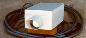
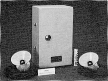
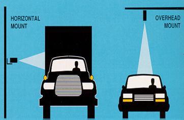
Sumitomo SDU-300 pulse ultrasonic sensor (Photograph courtesy of Lawrence A. Klein) Application and UsesPulse energy transmitted at two known and closely spaced incident angles allows vehicular speed to be calculated by recording the time at which the vehicle crosses each beam. Since the beams are a known distance apart, the speed is given by Eq. (5-1). Constant frequency ultrasonic sensors that measure speed using the Doppler principle are also manufactured. However, these are more expensive than pulse models. The preferred mounting configurations for range-measuring, pulsed ultrasonic sensors are downward looking and side viewing as shown in Figure 35. The range-measuring ultrasonic sensor transmits a series of pulses of width Tp (typical values are between 0.02 and 2.5 ms) and repetition period T0 (time between bursts of pulses), typically 33 to 170 ms. The sensor measures the time it takes for the pulse to arrive at the vehicle and return to the transmitter. The receiver is gated on and off with a user-adjustable interval that helps to differentiate between pulses reflected from the road surface and those reflected from vehicles. The detection gate is adjusted to detect an object at a distance greater than approximately 0.5 m above the road surface.
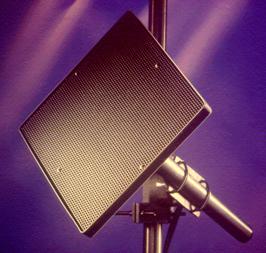
Figure 35. Mounting of ultrasonic range-measuring sensors. (Courtesy of Microwave Sensors, Ann Arbor , MI ). Automatic pulse-repetition frequency control reduces effects of multiple reflections and improves the detection of high-speed vehicles. This control is implemented by making the pulse repetition period as short as possible by transmitting the next pulse immediately after the reflected signal from the road is received (Kumagai, et al., 1992). A hold time Th (composite values from manufacturers range from 115 ms to 10 s) is built into the sensors to enhance presence detection. AdvantagesInstallation of ultrasonic sensors does not require an invasive pavement procedure. Also, some models feature multiple lane operation. DisadvantagesTemperature change and extreme air turbulence may affect the performance of ultrasonic sensors. Temperature compensation is built into some models. Large pulse repetition periods may degrade occupancy measurement on freeways with vehicles traveling at moderate to high speeds. MANUFACTURER AND VENDOR INFORMATION Effective Date: 2/29/00 Manufacturer name: Sales representative name(s): Sumitomo Electric Address: 1-1-3 Shimaya Address: Konohana-ku, Osaka 554-0024 Japan Phone number: +81 6-6461-1031 Phone number: Fax number: +81 6-6466-3305 Fax number: e-mail address: www@prs.sei.co.jp e-mail address: URL address: www.sel.co.jp URL address: PRODUCT NAME/MODEL NUMBER: SDU-420 FIRMWARE VERSION/CHIP NO.: N/A SOFTWARE VERSION NO.: N/A GENERAL DESCRIPTION OF EQUIPMENT: Ultrasonic Vehicle Detector SENSOR TECHNOLOGY AND CONFIGURATION: Ultrasound SENSOR INSTALLATION: Overhead INSTALLATION TIME (Per Lane ): INSTALLATION REQUIREMENTS: Pole arm MAXIMUM NUMBER OF LANES MONITORED SIMULTANEOUSLY: One lane/head PRODUCT CAPABILITIES/FUNCTIONS: Presence, occupancy, classification (two) RECOMMENDED APPLICATIONS: Advanced traffic signal control, freeway monitoring, POWER REQUIREMENTS (watts/amps): 160 VA POWER OPTIONS: N/A CLASSIFICATION ALGORITHMS: Vehicle height TELEMETRY: N/A COMPUTER REQUIREMENTS: NO DATA OUTPUT: NEMA TS1, custom DATA OUTPUT FORMATS: N/A SUPPORTING DATA BASE MANAGEMENT SYSTEM: N/A EQUIPMENT AND INSTALLATION COSTS (One-lane and four-lane): Approx. $1,900/one lane & installation cost STATES CURRENTLY USING THIS EQUIPMENT: Country/State Contact name Telephone number Japan Passive Acoustic Array SensorsAcoustic sensors measure vehicle passage, presence, and speed by detecting acoustic energy or audible sounds produced by vehicular traffic from a variety of sources within each vehicle and from the interaction of a vehicle's tires with the road. When a vehicle passes through the detection zone, an increase in sound energy is recognized by the signal-processing algorithm and a vehicle presence signal is generated. When the vehicle leaves the detection zone, the sound energy level drops below the detection threshold and the vehicle presence signal is terminated. Sounds from locations outside the detection zone are attenuated. Principles of OperationTwo models of acoustic sensors are marketed. Both detect the sounds produced by approaching vehicles with a two-dimensional array of microphones. The SmartSonic acoustic sensor shown on the left in Figure 36 detects vehicles by measuring the time delay between the arrival of sound at the upper and lower microphones, which are arranged in a vertical and horizontal line through the center of the aperture. The time delay changes as the vehicle approaches the array. When the vehicle is inside the detection zone, the sound arrives almost instantaneously at the upper and lower microphones. When the vehicle is outside the detection zone, sound reception at the upper microphone is delayed by the intermicrophone distance. The size and shape of the detection zone are determined by the aperture size, processing frequency band, and installation geometry of the acoustic array. The SmartSonic sensor is tuned to a center frequency of 9 KHz with a 2 KHz bandwidth. Preferred mounting is at 10 to 30 degrees from nadir with a detection range of 20 to 35 ft (6 to 11 m). The speed of a detected vehicle is determined with an algorithm that assumes an average vehicle length. Vehicle presence detection is through an optically isolated semiconductor. When the optional acoustic sensor controller board is installed in a NEMA or 170 cardfile, two detection zones can be used in a speed trap mode to measure vehicle speed. The speed trap activates relay outputs that simulate two inductive loops connected to a NEMA or 170 controller. The SAS-1 acoustic sensor on the right in Figure 36 uses a fully populated microphone array and adaptive spatial processing to form multiple zones that receive the acoustic energy from up to 5 lanes when the sensor is mounted at the side of a roadway. During setup, the detection zones are steered to positions that correspond to the monitored traffic lanes. The detection zones are self normalized and polled for vehicles every 8 ms. Detection zones are adjustable to 6 ft (1.8 m) or 12 ft (3.6 m) in the direction of traffic flow and have user-specified values in the cross-lane direction. Acoustic frequencies between 8 and 15 kHz are processed by this sensor, which accommodates mounting heights of 20 to 40 ft (6 to 12 m). Application and UsesThe SmartSonic is recommended for data collection applications on bridges and other roads where over-roadway sensors are required and where slow moving vehicles in stop and go traffic flow are not present.
Figure 36. Acoustic array sensors. The output data provided by the SAS-1 are volume, lane occupancy, and average speed for each monitored lane over a user-specified period (e.g., 20s, 30s, 1 min). Vehicle presence is provided by an optional relay interface. AdvantagesInstallation of passive acoustic array sensors does not require an invasive pavement procedure. Acoustic sensors are insensitive to precipitation and multiple lane operation is available in some models. DisadvantagesCold temperatures have been reported as affecting the accuracy of the data from acoustic sensors. Also, specific models are not recommended with slow moving vehicles in stop and go traffic. MANUFACTURER AND VENDOR INFORMATION Effective Date: March 22, 2000 Manufacturer name: International Road Sales representative name(s): Dynamics, Inc. Rod Klashinsky Address: 702 43rd Street East Address: Saskatoon SK , S7K 3T9 Canada Phone number: 306-653-6600 Phone number: Fax number: 306-242-5599 Fax number: e-mail address: info@irdinc.com e-mail address: URL address: www.irdinc.com URL address: PRODUCT NAME/MODEL NUMBER: IRD SmartSonic™ Vehicle Detection System FIRMWARE VERSION/CHIP NO.: N/A SOFTWARE VERSION NO.: N/A GENERAL DESCRIPTION OF EQUIPMENT: The IRD Smartsonic™ Vehicle Detection System is based on acoustic-sensing and signal processing technologies. The SmartSonic™ sensors are mounted non-intrusively above or beside roadways on existing structures such as bridges, overhead traffic signs or light poles. Structures may be installed specifically to mount the sensors if required. IRD SmartSonic™ Vehicle Detection Systems are ideal for detection of vehicles on roadways where lane closure is not an option. SENSOR TECHNOLOGY AND CONFIGURATION: SmartSonic™ detectors are acoustic-sensing technology for vehicle detection. A single detector provides vehicle detection per lane. SENSOR INSTALLATION: Sensors may be installed above or beside roadways using existing structures or specifically installed structures. INSTALLATION TIME (Per Lane ): Typically 4 hours. INSTALLATION REQUIREMENTS: Please see attached product information for details. MAXIMUM NUMBER OF LANES MONITORED SIMULTANEOUSLY: Four SmartSonic™ sensors can interface to a single SmartSonic™ controller to monitor 4 lanes. PRODUCT CAPABILITIES/FUNCTIONS: Vehicle detection, Traffic counting, Occupancy Counts per lane of Traffic. RECOMMENDED APPLICATIONS: Vehicle detection, Traffic counting, Occupancy Counts per lane of traffic in free-flow traffic at speeds of more than 30 MPH. POWER REQUIREMENTS (watts/amps): 12-24 VDC POWER OPTIONS: DC or solar. CLASSIFICATION ALGORITHMS: Up to 3 classes. TELEMETRY: Yes COMPUTER REQUIREMENTS: A laptop computer may be used for information retrieval with serial communication software such as HyperTerminal. DATA OUTPUT: Serial or contact closure. DATA OUTPUT FORMATS: ASCII SUPPORTING DATA BASE MANAGEMENT SYSTEM: N/A EQUIPMENT AND INSTALLATION COSTS (One-lane and four-lane): 1-lane: $4,000 US 4-lane: $12,000 US STATES CURRENTLY USING THIS EQUIPMENT: Country/State Contact name Telephone number USA/Massachusetts USA/Texas USA/Arizona MANUFACTURER AND VENDOR INFORMATION Effective Date: 7/3/07 Manufacturer name: SmarTek Systems Sales representative name(s): Greg Pieper Address: 14710 Kogan Drive Address: 295 Waycross Way Woodbridge , VA 22193 Arnold , MD 21072 Phone number: (410) 315-9727 Phone number: (410) 315-9727 Fax number: (410) 384-9264 Fax number: (410) 384-9264 e-mail address: sales@smarteksys.com e-mail address: sales@smarteksys.com URL address: URL address: www.smarteksys.com PRODUCT NAME/MODEL NUMBER: SAS-1 FIRMWARE VERSION/CHIP NO.: SOFTWARE VERSION NO.: GENERAL DESCRIPTION OF EQUIPMENT: The SAS-1 is a non-intrusive, true presence vehicle detector providing traffic count, occupancy, and per vehicle speed information, and can store up to 60 days of data. It can be connected to existing traffic controllers via RS-232 serial port or opto-coupled relay. Each sensor provides up to five lanes of dual-loop, speed trap equivalence when installed from a side-fire position. SENSOR TECHNOLOGY AND CONFIGURATION: Passive acoustic SENSOR INSTALLATION: Side-fire mounted 25 to 40 ft (76 to 122 m) above the pavement. The horizontal distance to the first detection one is 5 to 30 ft (15 to 91 m). INSTALLATION TIME (Per Lane ): 5 minutes INSTALLATION REQUIREMENTS: Pole mount; bucket truck MAXIMUM NUMBER OF LANES MONITORED SIMULTANEOUSLY: Five PRODUCT CAPABILITIES/FUNCTIONS: True presence, traffic count (volume), speed (average and per vehicle), lane occupancy, up to 60 day data storage (dependent on memory: 1, 2, or 4 Mbits). RECOMMENDED APPLICATIONS: Traffic monitoring of highways, etc. POWER REQUIREMENTS (watts/amps): 8-24 VDC, <2W. POWER OPTIONS: None CLASSIFICATION ALGORITHMS: Up to 3 levels of vehicle classification. TELEMETRY: Wireless 2.4 GHz spread spectrum optional. COMPUTER REQUIREMENTS: DATA OUTPUT: See Product Capabilities/Functions DATA OUTPUT FORMATS: RS-422 standard, RS-232 optional. SUPPORTING DATA BASE MANAGEMENT SYSTEM: EQUIPMENT AND INSTALLATION COSTS (One-lane and four-lane): STATES CURRENTLY USING THIS EQUIPMENT: Country/State Contact name Telephone number USA/Arizona Tim Wolf (602) 712-6622 USA/Arizona Glenn Jonas (602) 712-6587 USA/Idaho Jim Larsen (208) 387-6197 USA/Virginia Cyndi Ward (804) 692-0390 USA/Virginia Mr. Stephany Hanshaw (757) 464-9907 USA / New York Bill Platt (607) 324-8412
|