U.S. Department of Transportation
Federal Highway Administration
1200 New Jersey Avenue, SE
Washington, DC 20590
202-366-4000
Federal Highway Administration Research and Technology
Coordinating, Developing, and Delivering Highway Transportation Innovations
 |
| This report is an archived publication and may contain dated technical, contact, and link information |
|
Publication Number: FHWA-HRT-05-068 Date: October 2005 |
Curvature is a key concept in structural analysis and applied mechanics, especially in the area of soil-structure interaction problems. The mathematical expression for curvature for function, z = f(x), which in this case is an elevation = f(distance) profile along a jointed concrete pavement, is as shown in figure 129:
Figure 129. Equation. Kappa.
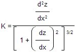
A key assumption in applied mechanics is the assumption of small strains or small changes in curvature from the initial state to the stressed state. When the slope, dz/dx, (or change in slope for structural analysis) is small, the bottom component of the above equation for curvature is very close to a value of 1. This allows the following simplified small strains approximation for curvature when there is a small slope, as shown in figure 130:
Figure 130. Equation. Curvature.![]()
In the case of a road profile, the unit for curvature is 1/L, where L is a length unit. Whenever a stress in a concrete pavement is calculated from a wheel load or curling/warping phenomena, the soil-structure interaction problem is first solved using equations of equilibrium for curvature. The pavement materials and thickness are then used to estimate stress for the solved values of curvature, which are based on the relative stiffness of the slab and foundation support. Slabs, including pavements, can be modeled in three dimensions with partial differential equations of form similar to that shown in figure 131:(38)
Bending in the X direction in a thin slab:
Figure 131. Equation. Mx.![]()
where,
| Mx = Bending moment. |
| E = Slab elastic modulus. |
| h3 / 12 = Moment of inertia of a unit wide slab element of height,h. |
| μ = Poisson's ratio for the slab material. |
Flexural stress in a slab or beam is then related to the moment by figure 132:
Figure 132. Equation. Sigma.![]()
where,
| y = Distance from the neutral axis of the slab (mid-depth). |
| σ = Stress at a distance y from the neutral axis. |
The analysis of curvatures and stress in rigid pavements is primarily based on Westergaard's research from the 1920s for predicting PCC slab deflections and stresses for wheel loads(39) and for temperature warping.(38) Based on that research and some recent trends, the equations in figures 133 and 134 are key moment-curvature equilibrium equations representing pavement slabs:
Figure 133. Equation. Negative second derivative of z over x.![]()
Figure 134. Equation. Negative second derivative of z over y.![]()
where,
| A = Temperature-related curvature, curling = f(t). |
| B = Moisture-related curvature, warping = f(t). |
| C = Construction-related curvature = f(A,x,y,t). |
| D = Long-term curvature creep = f(A,B,C,x,y,t). |
| Mx, My = Bending moments in the slab = f(A,B,C,D,x,y,t). |
These two moment-curvature equilibrium equations can be more intuitively thought of as having the form in figure 135:
Figure 135. Equation. Кtotal.![]()
Although A, B, C, and D curvature components vary over the area of the slab, the A and B components (in situ temperature- and moisture gradient-related curvatures) can generally be assumed to be close to constant over the slab area. However, the construction-related curvature and the creep of curvature over time, which is caused by stress relaxation in the slab or subgrade, are generally not constant over the slab area but are a function of the soil-structure interaction's sensitivity to joint spacing, foundation type, materials, and the like. The soil structure interaction is a function of all the various effects and slab geometry.
Modern profiling devices measure a profile of the total curvature in each slab from all of the curvature causing factors. They measure a slice through the solution (κtotal) for those partial differential equations shown previously. It is not easy to determine how much of the total curvature is occurring from each of the different types of curvature and thus it is also very difficult to quantify how much stress is actually present. The pavement profile can be divided into two separate matrices: one with only continuous slab segment data and one with only data for zones immediately around probable faults and cracks or questionable data. The following two categories of slab shape features are quantified:
Inertial profiling devices actually obtain a discontinuous profile consisting of evenly spaced point elevations, which can be conveniently analyzed using finite difference methods. The slope and curvature anywhere along the profile, for any span length, can readily be estimated using the finite difference forms of the first and second derivatives as follow in figures 136 and 137:
Figure 136. Equation. First derivative of z over x.![]()
Figure 137. Equation. Second derivative of z over x.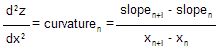
where,
| i = 1 for 152.4-mm (6-inch) interval data points. |
| i = 2 for 304.8-mm (12-inch) interval data points. |
| i = 3 for 457.2-mm (18-inch) interval data points. |
| i = 4 for 604.6-mm (24-inch) interval data points. |
| i = 5 for 762-mm (30-inch) interval data points. |
| i = 6 for 914.4-mm (36-inch) interval data points. |
| i = 7 for 1,066.8-mm (42-inch) interval data points. |
| i = 8 for 1,219.2-mm (48-inch) interval data points. |
The computation of CI is illustrated using data obtained at a 152.4-m (500-ft) length GPS-3 section. The LTPP inertial profiler collected data at 25-mm (1-inch) intervals, but profile data elevations are moving-averaged to 152.4-mm (6-inch) intervals. The elevation value reported at a given point on the profile is the average of the surrounding 12, 25-mm (1-inch) interval elevation samples, or ±152.4 mm (6 inches), which is a moving average filter. These filtering techniques significantly reduce long wavelength vertical curves and micro/macro texture features having short wavelengths from the final profile data.
Slab curvature estimates were obtained by calculating curvature using the moving-arc finite difference second derivatives, using several different base lengths across a slab. Profile data within about 0.75 to 1 m (2 to 3 ft) of imperfections are separated from the apparent continuous portions of the profile data. Within each of these isolated slab zones, moving 0.152-, 0.305-, 0.457-, 0.610-, 0.762-, 1.067-, and 1.219-m (6-, 12-, 18-, 24-, 30-, 36-, 42-, and 48-inch) interval curvatures are calculated at 152.4-mm (6-inch) intervals over the full length of the individual slab segments between the imperfections using the three-point moving arc type data filter. This procedure is performed for all isolated slab zones within the section. For each wheel path, all previously described curvature values are averaged to obtain the CI of the wheel path. Thereafter, the CI values for the two wheel paths are averaged to obtain the overall CI of the section.

