U.S. Department of Transportation
Federal Highway Administration
1200 New Jersey Avenue, SE
Washington, DC 20590
202-366-4000
Federal Highway Administration Research and Technology
Coordinating, Developing, and Delivering Highway Transportation Innovations
 |
||
 | report |  |
| This report is an archived publication and may contain dated technical, contact, and link information | ||
| Federal Highway Administration > Publications > Research > Infrastructure > Structures > Geosynthetic Reinforced Soil Integrated Bridge System Interim Implementation Guide |
Publication Number: FHWA-HRT-11-026
Date: January 2011 |
Geosynthetic Reinforced Soil Integrated Bridge System Interim Implementation GuideCHAPTER 7. CONSTRUCTION7.1 INTRODUCTIONGRS construction uses basic earthwork methods, primarily for excavation and compaction, along with sound general construction practices. The materials are readily available, which is a benefit of the generic nature of the system. This chapter provides guidance on most field–related scenarios. All methods that are presented have been field–tested and applied during the construction of GRS-IBS. The techniques outlined can be applied to efficiently construct the layered system and have been proven to quickly construct the GRS–IBS. The contractor will ultimately choose the methods most efficient for the site, the crew, and the equipment on hand. The guidance outlined here applies to GRS structures, specifically abutments built with CMU blocks. This guidance can also be adapted to other GRS structures built with different facing systems. GRS construction has two principal components: (1) logistics and (2) aspects associated with actual construction. Logistics occur after the final design and before construction, outlining a plan for implementation and control of the construction process. Even though building a GRS abutment is as simple as a row of facing block, a layer of well–compacted granular fill, and a sheet of reinforcement, the process will be hampered without adequate planning to ensure optimum flow and placement of material during the course of the project. As a result, the single–sheet plan was devised to provide information on the reinforcement schedule and the facing block schedule. The single–sheet plan also contains information on the limits of excavation and details about assembly of the GRS structure. A second sheet may be necessary to detail quantities and construction notes. This chapter conveys the importance of the following details as a means to rapid GRS construction:
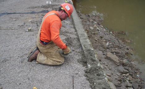
7.2 LABOR AND EQUIPMENT7.2.1 Labor Requirements A typical labor crew on GRS–IBS projects has consisted of about five workers: four laborers and an equipment operator (see figure 40 ). The equipment operator is central to the project and provides support to the labor crew. The equipment operator is responsible for shaping the excavation to facilitate construction of the RSF and the GRS abutment in addition to placing fill material and moving facing units into the work area. Typically, one member of the labor crew has the role of foreman and is responsible for layout of excavation limits, grades, alignment of wall face, placement of facing blocks, compaction of fill, placement of geosynthetic reinforcement, and other activities to streamline production and the flow of material to the job site.
Figure 40. Photo. Typical labor crew with centrally located track hoe. 7.2.2 Tool and Equipment Requirements Specialized equipment is not required to construct GRS–IBS. Simple tools that are readily available and relatively inexpensive can be used. These include hand tools, measuring devices, and heavy equipment. The contractor may modify the included lists depending on the site, the crew, and the size of the IBS. Typical hand tools include the following:
Typical measuring devices include the following:
Typical heavy equipment includes the following:
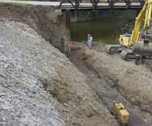
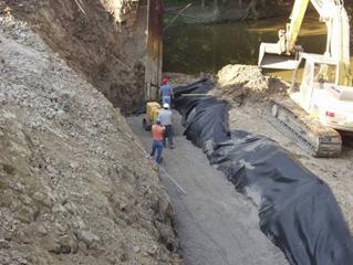
7.3 SITE PREPARATIONGRS is built from the bottom up and generally from within the footprint of the structure. Staging and delivery of materials to the site should allow for continuous GRS construction and effective use of the space. Delivered material should be easily accessible to the excavator, which is the central piece of equipment. As shown in figure 41, the excavator is positioned inside the wall area for easy placement of fill, block, and other materials. Labor should be organized to assemble construction materials as needed on the work platform.
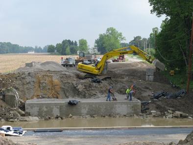
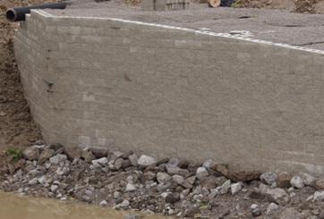
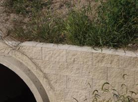
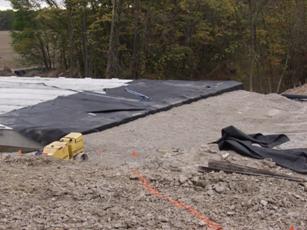
Figure 41. Photo. Cut slope of retained soil. 7.3.1 Site Layout Site preparation begins with a survey of the bridge site to stake limits for the excavation. Reference stakes should be located in an area where they will remain undisturbed during construction of the base of the wall, usually about 5 ft from the excavation. The base of the GRS abutment and wing walls should be constructed to within 1 inch of the staked elevations. The external GRS abutment and wing walls should be constructed to within ±0.5 inches of the surveyed staked dimensions. 7.3.2 Excavation All excavations should comply with Occupational Safety and Health Administration requirements.( 21 )Excavation of the site involves shaping the slope for temporary slope stability, safety, and constructability. The temporary cut in the retained soil should be designed to accommodate movement of labor. The design of a temporary excavation needs to consider the loading imposed by heavy equipment and the reach limits of the excavator. figure 41 shows a typical cut slope in stiff clay. The excavation should include provisions for drainage with a sloped cut to facilitate the movement of water. Any open excavations that form a pit should be backfilled with crushed aggregate and compacted. Excavation also includes the clearing and grubbing of vegetation. In situations where the retained fill is stable, the volume of excavation can be limited to reduce the size of the GRS mass. In the case of an abutment application, this would form a horseshoe shaped excavation, as shown in figure 40 and figure 42.
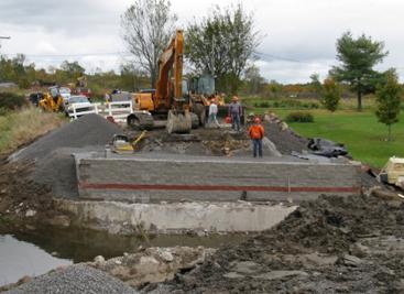
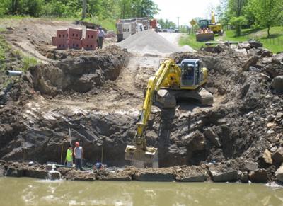
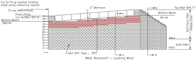
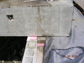
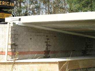
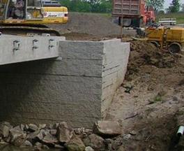
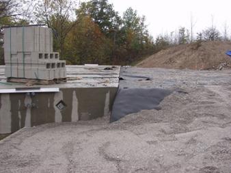
Figure 42. Photo. Horseshoe–shaped excavation with native soil still intact in middle. 7.3.3 Placement of Abutment Behind Existing Substructure In some situations, it may be beneficial to build GRS–IBS behind an existing substructure. Project feasibility, environmental considerations, and other factors need to be assessed before selecting this type of project layout. Building the bridge behind an existing substructure often requires the removal of the top part of the abutment walls to provide additional space for the width of the new GRS–IBS. figure 43 through figure 45 illustrate this technique. Note that the design of the GRS-IBS will be the same whether it is built behind an existing abutment or not.
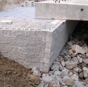
Figure 43. Photo. GRS–IBS built behind an existing concrete abutment.
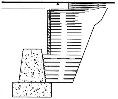
Figure 44. Illustration. Cross section of GRS–IBS built behind an existing concrete abutment.
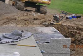
Figure 45. Photo. Building the RSF behind an existing abutment.
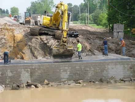
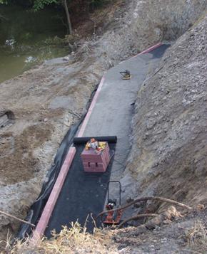
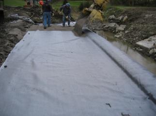
7.4 RSFThe depth and footprint of the excavation for the RSF should be based on external stability, as described in chapter 4. The base of the RSF should be cut smooth. It should be excavated to uniform depth, and all loose, unstable material should be removed from the site (see figure 46 ). If the base of the excavation is left open, it should be graded to one end to facilitate the removal of any intrusion of water with a pump. If flooded, all water should be removed along with soft, saturated soils. The excavation should be backfilled as soon as possible to provide a suitable foundation and avoid adverse weather delays. The construction of the RSF can typically be completed in less than one day but is dependent on the size and depth of excavation, type of materials, equipment, and experience.
Figure 46. Photo. RSF excavation below stream level. The base of the excavation should be compacted before construction of the RSF. This may require proof rolling, and any soft spots or voids should be backfilled with compacted fill material. Figure 47 shows the preparation of the RSF cut.
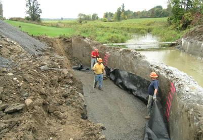
Figure 47. Photo. RSF cut preparation. The RSF should be encapsulated in geotextile reinforcement placed perpendicular to the abutment face to protect it from possible erosion (see figure 48 ). The reinforcement sheets should be measured and sized to fully enclose the RSF on three sides: the face and the two wing wall sides. If the GRS abutment is adjacent to water, the reinforcement sheets should overlap, starting with the first layer on the upstream side of the RSF. All overlapped sections of reinforcement in the area of the RSF should be oriented to prevent running water from penetrating the layers of reinforcement. The first layer of reinforcement should be placed on the upstream side of the abutment with subsequent layers, if needed, overlapped a minimum of 3 ft on the downstream side. This prevents water from infiltrating the RSF. The wrapped corners of the RSF need to be tight and without exposed soil within the RSF to complete the encapsulation.
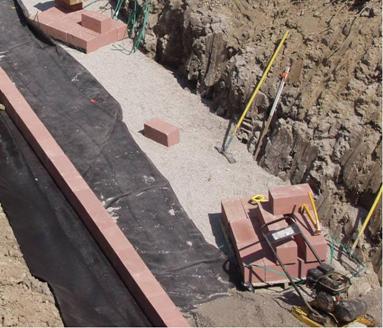
Figure 48. Photo. Encapsulation of fill in RSF. Typical reinforcement spacing in the RSF is 12 inches. The reinforcement should be pulled taught to remove all wrinkles prior to placing and compacting the structural backfill. Fill should be placed from the face to the back to roll folds or wrinkles to the free end of the reinforcement layer. The RSF should be constructed with structural fill, as specified in chapter 3. The structural fill is to be compacted in accordance with section 7.5 in compacted lifts not to exceed 6 inches (with two compacted lifts per each 12–inch layer). The first course of wall block sits directly on the RSF, as shown in figure 49 , so it is important that the fill material is graded and level before encapsulating the RSF.
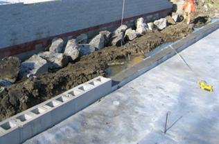
Figure 49. Photo. Placement of wall block on wrapped RSF. While the base of a typical GRS abutment is built with solid CMU, damage can occur during the placement of channel rock protection or from other large pieces of concrete rubble that extend above the solid block zone. Riprap protection should be placed in a manner to prevent damage to the CMU wall face. Impact of large rock or concrete fragments during placement can crack the CMU block. Larger rocks should be uniformly distributed and placed firmly in contact with each other, with smaller rocks and fragments filling the voids between the larger rocks. This procedure often requires hand placement of smaller rocks to fill the voids. If any CMU block is damaged, refer to chapter 8 for repair procedures.
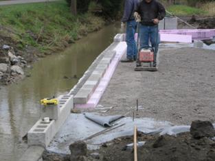
7.5 COMPACTIONCompaction of the backfill should be to at least 95 percent of maximum dry density according to AASHTO T–99. Backfill material containing fines should be compacted at a moisture content close to optimum (±2 percent). Lifts of 8 inches should be compacted using vibratory roller compactionequipment. The facing blocks provide a form for each lift of fill. Other stiffness–based compaction control methods can be used. For open–graded fills, compact to non–movement or no appreciable displacement and assess with visual inspection. Since the facing elements are not rigidly connected to the reinforcement, hand–operated compaction equipment (e.g., a lightweight mechanical tamper, plate, or roller) is required within 1.5 ft of the front of the wall face. It is very important for adequate GRS performance that the backfill is properly compacted. The top 5 ft of the abutment should be compacted to 100 percent of the maximum density according to AASHTO T–99. Onsite compaction equipment should be selected to achieve the required density of the fill materials. Considering that compaction is critical to the success of the project, compaction equipment should be in good operating order for efficient use. In addition, backup equipment should be available to provide quality construction throughout the project and to avoid construction delays. 7.5.1 Compaction Procedure Once fill is placed at the required thickness and graded, all areas behind the CMU block should be compacted to the required density. Any depression behind the facing block should be filled level to the top of the CMU block prior to compaction. Compaction directly behind the CMU block should be performed in a manner that maintains wall alignment while improving the density of fill behind the block. This can be achieved in the following ways:
The most common compaction QC tool is the nuclear density gauge. Other instruments are also available for compaction control such as the Clegg hammer, the soil stiffness gauge, or the falling weight deflectometer. These devices are typically used by correlating their measurements to soil density and moisture content. Method–based compaction specifications can also be used. For open–graded fills, compact to non–movement or no appreciable displacement and assess with visual inspection.
7.6 REINFORCEMENT
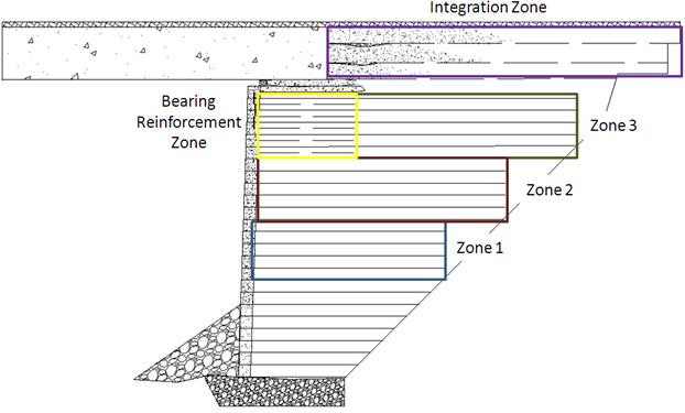
Generally, the length of the reinforcement layers will follow the cut slope, as shown in figure 50. While the reinforcement layers in the GRS abutment can be any geosynthetic, the RSF and integrated approach should be constructed and encapsulated with a geotextile to confine the compacted granular fill. The geosynthetic should be placed so that the strongest direction is perpendicular to the abutment face, as shown in figure 51. Where the roll ends, the next roll should begin.
Figure 50. Illustration. Typical reinforcement zones.
Figure 51. Reinforcement rolled out parallel to wall face. After the geosynthetic is rolled out, it should be laid so that it is taut, free of wrinkles, and flat. The geosynthetic can be held in place with the fill. Placement of fill should be from the wall face backward to remove and prevent the formation of wrinkles in the geosynthetic. A conscious effort should be taken during placement of fill to prevent the development of wrinkles. Splices of reinforcement can occur without overlap. Splice seams should be staggered to avoid a continuous break in the reinforcement throughout the GRS structure. All splice seams should run perpendicular to the wall face. Overlaps of adjacent geosynthetic should be trimmed where they are in contact with the surface of the CMU block to avoid varying geosynthetic thicknesses between the CMU block. Any seams in the geosynthetic should be staggered with each successive layer of the GRS abutment. All seams between adjacent sheets of geosynthetic located in the area beneath the footprint of the bridge seat should be perpendicular to the abutment wall face. 7.6.1 Operating Equipment on Geosynthetic Reinforcement
Driving should not be allowed directly on the geosynthetic reinforcement. Place a minimum 6-inch layer of granular fill prior to operating any vehicles or equipment over the geosynthetic reinforcement. In the bearing reinforcement zone, hand-operated compaction equipment should be used over the 4-inch lifts to prevent excessive installation damage of the reinforcement. Rubber–tired equipment may pass over the geosynthetic reinforcement at speeds less than 5 mi/h. Skid steers and tracked vehicles can cause considerable damage to the geosynthetic. On one occasion, a track hoe operating on a GRS structure turned and pulled the fabric causing deformation to the wall face. For this reason, it is recommended to restrict the use of these vehicles on GRS structures. If absolutely necessary, use may be permitted provided no sudden braking or sharp turning occur and a minimum 6–inch cover is placed. 7.6.2 Bearing Reinforcement Bed The bearing reinforcement bed provides additional strength in the upper GRS wall layers directly beneath the bearing area of the superstructure. These reinforcement layers are not sandwiched between two consecutive rows of block but are placed behind the CMU block at 4–inch spacing. This 4–inch reinforcement spacing is generally placed in the top five layers of the GRS abutment or as determined by design (see chapter 4). Bearing bed reinforcement spacing in superelevated abutment walls requires additional planning. The 4–inch reinforcement spacing needs to be in place for the top five courses of block at the lowest elevation across the abutment wall (see figure 50 and figure 52 ). The reinforcement schedule will guide field personnel in the proper placement of the geosynthetic along a wall block course.
Figure 52. Illustration. Superelevation reinforcement schedule. 7.6.3 Superelevation The reinforcement layers become stair–stepped in the upper wall layers as the superelevation of the abutment is constructed (see figure 53 ). The reinforcement terminates along the angle surface of the superelevation. The GRS wall reinforcement schedule should show the termination of each layer of reinforcement across the abutment wall from low to high elevation (see figure 52 ).
Figure 53. Photo. Superelevation reinforcement layers.
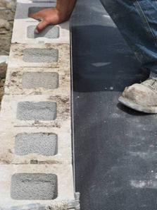
7.7 WALL FACEThis manual focuses on the use of CMU for the wall facing; however since GRS is internally stable, any facing elements can be used in construction. For flexible facings other than the recommended CMU block (including wrapped, timber, natural rock, or welded wire basket formed facing), other construction guidelines may need to be followed. These are outlined by Wu et al.( 22 ) The design guidelines for GRS–IBS, however, remain the same as those in this manual. 7.7.1 Leveling Course Setting the first course of facing block level and to grade is critical in maintaining wall alignment for the entire height of the abutment. Typically, the first course is placed on top of the RSF, directly on the geotextile. However, due to the large aggregate size of the RSF fill material, a thin leveling layer of fine aggregate can help set the CMU blocks to grade and prevent them from rocking. The leveling layer should be kept to a minimum thickness, no more than 0.5 inches. If the leveling layer exceeds this thickness and there is the potential for water to erode and undermine the aggregate, mortar or grout should be placed in the gap between the RSF and the first course. 7.7.2 Setting the CMU Block CMU block wall construction should begin at the lowest portion of the excavation with each layer placed horizontally, as shown on the plans. Each layer should be constructed entirely before beginning the next layer. A stretcher or running bond should be maintained between courses of block so that the joints between the blocks are offset with each row. If a designed scour countermeasure such as a riprap apron is used, a geotextile filter fabric should be placed under the apron and anchored between the first and second courses of CMU block. Since the CMU blocks are dry stacked without mortar, it is important to avoid cracking the block and to maintain a horizontal uniform elevation by sweeping the top surface of the block clean of debris and fill material prior to the placement of the next layer of geosynthetic and CMU block. Gravel material between layers of block creates point loads that can cause cracks. Also, gravel material between the blocks causes them to rock, making it difficult to secure a good fit. When setting a course of block, each block should be placed tightly against the adjoining block, preventing gaps from which fill material can escape. Before proceeding to the next layer, it is often useful to walk along the top of the blocks to easily identify a poorly seated block. In order to avoid cutting a block when the CMU block schedule shows the wall terminating with half a block, a full CMU block can be turned 90 degrees, placing the 8–inch width toward the face. This typically occurs at the termination of a wing wall. The end block that forms the termination does not have to be a corner CMU (with two finished sides) because the ends of most wing walls are embedded into the fill slope. 7.7.3 Wall Face Alignment When placing and compacting fill behind the CMU block, it is sometimes necessary to set the block back about 0.5 inches to allow for lateral outward movement of the CMU block during compaction. It should be noted that each combination of wall facing and backfill reacts differently during the compaction process, and adjustment of the setback distance between block courses should be performed as needed to maintain the necessary batter. The vertical GRS wall should be checked for plumbness at least every other layer, and any deviations greater than 0.25 inches should be corrected. Before placement of the backfill, every other row of block alignment should be checked with a string line referenced off the back of the facing block from wall corner to corner (see figure 54 ).
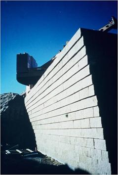
Figure 54. Photo. Checking block alignment with string line reference from back of block. If CMU blocks become displaced during construction, they can often be hammered back into position using a 3–lb sledgehammer and a block of wood as protection. If the CMU block is excessively out of alignment, the fill material needs to be excavated, the CMU block repositioned, and the fill material replaced and recompacted. 7.7.4 Block Alignment for Battered Walls Block alignment for battered walls is similar to that for vertical walls. In abutment situations where the face wall turns to form the wing wall, however, it is necessary to trim blocks on either end to account for the reduced wall length. All cuts should be performed to maintain the standard running or stretcher bond between the rows of dry–stacked blocks, with the vertical joints of each course midway between those of adjoining courses. In special situations, negative battered walls have been constructed when the top area needs to be greater than the bottom, as in the case of road widening shown in figure 55. The negative batter can be created by offsetting the CMU block by a measured amount in consecutive wall layers then filling and compacting as specified.
Figure 55. Photo. Negative batter wall face. 7.7.5 Superelevation When the plan shows a superelevation for the bridge, the top courses of CMU beneath the superstructure should be trimmed to match the elevation difference and clear space across the abutment (see figure 56 ). This will produce a sloped face wall and aid in construction of the beam seat. One method is to snap a chalk line along the back of the block at the superelevation slope. A carpenter's angle finder can also be used to mark the cut.
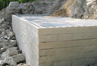
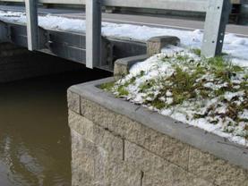
Figure 56. Photo. Blocks trimmed to match superelevation. 7.7.6 Wall Corners Right–angle wall corners, as shown in figure 57, are constructed with CMU corner blocks that have architectural detail on two sides, providing an aesthetic finish. Facing wall and wing wall courses should be staggered to form a tight, interlocking, stable corner.
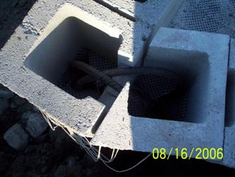
Figure 57. Photo. Right–angle wall corner. Walls with angles larger or smaller than 90 degrees require additional effort. The corner blocks need to be cut to form the angled face. As a result, a vertical seam or joint is formed at the corner (see figure 58 ). Corners with vertical seams may have open block joints, making it prudent to fill the corner blocks with a concrete mix and install bent rebar to close and connect the seam at each course of block, as shown in figure 59. This procedure secures the two faces and prevents compaction–induced separation during construction of subsequent GRS layers. It may also be used wherever added strength at the wall corner is desired.
Figure 58. Photo. Vertical seam in wing wall.
Figure 59. Photo. Rebar installed in vertical seam prior to grout. 7.7.7 Top of Facing Wall The top three courses of CMU block in the abutment are susceptible to movement simply from not having the weight of successive layers holding them in place. To prevent displacement, the hollow cores of the top three courses of CMU blocks are filled with a concrete wall fill and pinned together with No. 4 rebar, preferably epoxy–coated and embedded with a minimum 2–inch cover (see figure 60 ).
Figure 60. Photo. Connecting the top courses of blocks. To grout and pin the top of the wall, the reinforcement between the top two courses of CMU block needs to be removed to open the core for placement of concrete wall fill and a 20–inch–long No. 4 rebar dowel, preferably epoxy–coated with 2–inch cover (see chapter 3). This can be accomplished either by cutting the reinforcement with a razor knife or by burning the reinforcement. The concrete wall fill is placed in two steps. After the block void is filled with concrete to the top of the block and the steel rebar is inserted, a thin layer of the same concrete mix is placed on top of the block to form the coping cap, as shown in figure 61 and figure 62. The coping is then hand–troweled either square or round and sloped to drain. A wet–cast cap is more durable than a dry–cast cap and eliminates the need to furnish and install a separate cap unit.
Figure 61. Photo. Rounded coping cap.
Figure 62. Photo. Square coping cap. Once the top of wall has been grouted and pinned, care should be taken to avoid any construction activity that may pull on the top layer of reinforcement. The frictional connection between the block is strong, and when courses are pinned together, the entire grouted wall face can be pulled out of alignment.
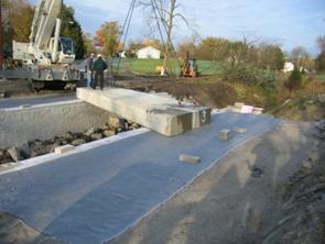
7.8 BEAM SEATThe beam seat is constructed directly above the bearing bed reinforcement zone. The superstructure is then positioned on top of the beam seat, as shown in figure 63 and figure 64. The purpose of the beam seat is to ensure that the superstructure bears on the GRS abutment and not the wall facing block and to provide the necessary clear space between the superstructure and the wall face. Typically, the clear space is 3 inches, or 2 percent of the abutment height, depending on the required design (see chapter 4).
Figure 63. Photo. Box beam placed on beam seat.
Figure 64. Photo. Detail view of box beam placed on beam seat. In general, the thickness of the beam seat is approximately 8 inches and consists of two 4–inch lifts of wrapped–face GRS. Remember, before construction of the beam seat, the cores of the CMU blocks on the abutment wall face must be pinned with No. 4 rebar and filled with concrete wall mix (see figure 65 ).
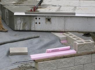
Figure 65. Photo. Bearing area block grouted prior to beam placement. 7.8.1 Beam Seat Procedure Once the block elevation beneath the bearing area is established and the hollow cores are filled with grout, the beam seat is ready for construction. The following steps should be used:
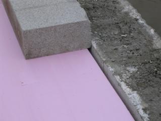
Figure 66. Photo. Foam board and 4–inch block assembly to form beam seat.
Figure 67. Photo. 4–inch concrete block on top of foam board against top CMU face block.
Figure 68. Photo. First 4–inch wrap butted against foam board.
Figure 69. Photo. Top 4–inch wrap butted against 4–inch solid block.
7.8.2 Setback The setback is the distance between the back of the facing block and the front of the beam seat. This distance can be established during construction of the beam seat and placement of the block and foam board used to form the beam seat wrap. The setback distance is usually 8 inches but can be greater. 7.8.3 Aluminum Flashing The aluminum flashing drip edge is installed prior to setting the bridge beams and is placed in between the bottom of the beams and the foam board. The flashing is held in place by the pressure of the beams on the compressible foam board (see figure 70 ). The length of the flashing should extend beyond the outside edge of the bridge beams and be trimmed to fit against the parapets.
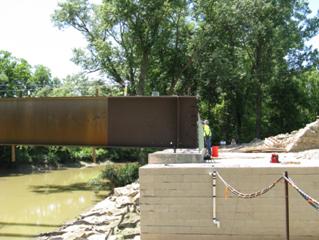
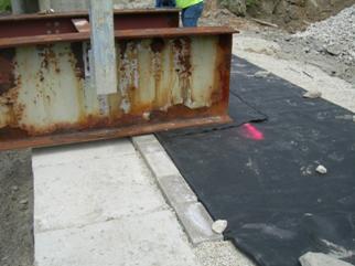
Figure 70. Photo. Aluminum flashing (drip edge) between beams and top of CMU block. 7.8.4 CIP or Precast Footing For GRS–IBS built without adjacent concrete beams, a CIP or precast footing may be necessary, as with steel beams or spread girders (see figure 71 ).
Figure 71. Photo. Steel girder on CIP footing.
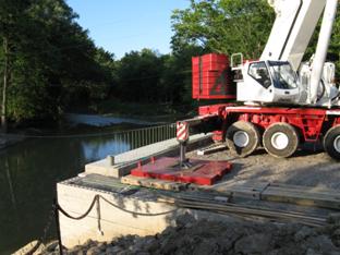
7.9 PLACEMENT OF SUPERSTRUCTUREPrepare the beam seat as described in section 7.8.1. The grade of the beam seat will control the final elevation of the bridge. 7.9.1 Crane Position on GRS Mass The crane used for placement of the superstructure can be positioned on the GRS abutment provided the outrigger pads are sized within the capacity of the GRS mass. The outrigger pads should be sized for 4,000 psf near the face of the abutment wall with greater loads able to be supported with increasing distance from the abutment face (see figure 72 ).
Figure 72. Photo. Outrigger pads near wall face. 7.9.2 Reinforcement of Beam Seat An additional layer of reinforcement should be placed between the beam seat and concrete or steel beams to provide additional protection of the beam seat (see figure 73 ). The additional layer of reinforcement may decrease the sliding resistance between the superstructure and the beam seat.
Figure 73. Photo. Additional reinforcement under beam. 7.9.3 Setting Superstructure on Beam Seat (Without CIP Footing) Since the bearing surface is aggregate under a layer of geosynthetic reinforcement, it is important to set beams square and level. They should never be dragged over the beam seat surface, which could create the potential for an uneven bearing area or a void under the beam, producing uneven bearing stresses between bridge elements. 7.9.4 Wing Walls and Parapets Wing walls and parapets are constructed after the superstructure is set. The CMU block in the parapet wall should be trimmed or saw cut for a custom fit against the beam edge to prevent the loss of fill material. Figure 74 and figure 75 show the construction of the parapet against the superstructure. If the gap between the superstructure and the facing block is difficult to fill using thin slices of cut block, a mortar mix should be used to close the space.
Figure 74. Photo. Parapet and wing wall construction, view 1.
Figure 75. Photo. Parapet and wing wall construction, view 2.
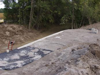
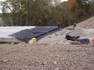
7.10 APPROACH INTEGRATIONProper approach construction at the road and superstructure interface is essential to minimizing settlement in front of the bridge beams and eliminating the bump at the end of the bridge. This is accomplished by compacting and reinforcing the approach fill in wrapped geotextile layers and blending the integration zone with the approach road base course. The material for the integration zone should be well–graded, as outlined in chapter 3. Once the superstructure is in place, the approach to the bridge can be constructed using the following steps:
Figure 76. Photo. Placing reinforcement.
Figure 77. Photo. First 6–inch fill lift.
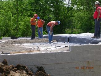
Figure 78. Photo. Secondary reinforcement sheet.
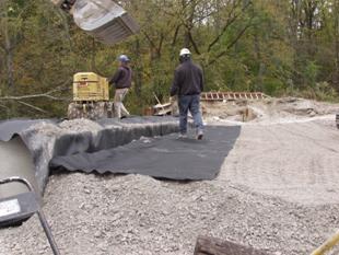
Figure 79. Photo. Completed wrapped approach layer.
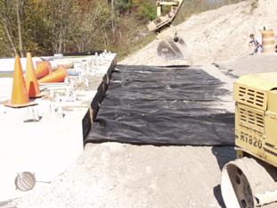
Figure 80. Photo. Second 6–inch fill lift. Multiple sheets can be used along the width of the approach, as long as all seams are kept perpendicular to the beam ends. The typical wrap reinforcement spacing is 12 inches, with intermediate layers spaced at 6 inches and compacted in 6–inch lifts. However, in the case of beams with a reduced depth, the spacing of the wrapped layers may need to be reduced and the intermediate layers eliminated. The top wrap fold should increase in length with each successive wrapped layer until the fill is 2 inches below the bridge grade. 7.10.1 Wrapped Reinforcement Layers on Sides If lateral spreading of the fill in the integrated approach will be an issue (e.g., wing walls are not sufficient to confine the fill at the sides), the reinforcement sheets comprising the wrapped layers should be folded over along the sides and perpendicular to the bridge (see figure 81 ).
Figure 81. Photo. Completed approach fill. 7.10.2 Preloading In some situations, it might be beneficial to preload the abutment before paving to minimize postconstruction deformation or settlement within the GRS mass. A simple method of preloading can be achieved be parking fully loaded trucks on the bridge for several days before placement of the asphalt pavement. 7.10.3 Paving The top layer of reinforcement should be kept approximately 2 inches below the beam grade. This will allow a layer of aggregate cover to be placed to protect the reinforcement from contact with hot mix asphalt. When GRS–IBS is built with adjacent precast concrete beams, a layer of paving fabric is extended over the beams onto the approach way. Extending the paving fabric 3 ft over the beam approach interface is recommended. This is necessary to bridge the gap and provide an interface to accommodate thermal movement, minimize surface water infiltration, and prevent cracks in the road. Note that paving fabric is already used on top of the beams as a barrier to water infiltration and to absorb stresses to minimize reflective and fatigue cracking of the new asphalt surface layer. 7.10.4 Guardrail Post Steel H posts are recommended for any railing that is driven through the reinforcement. It is also possible to drill through the GRS mass with an auger to set other types of posts.
7.11 SITE DRAINAGEThe GRS–IBS construction area should be protected from surface runoff during the project. Critical areas are behind the abutment wall at the interface between the GRS abutment and the retained fill, at the base of the abutment, and at any location where a fill slope meets the wall face. Design needs to include provisions for surface drainage along the fill slope adjacent to the wing walls. Provisions for drainage should also be included at the boundary of the wing walls and the fill slope. Long walls built along variable elevation or abutment wing walls are often stepped to reduce excavation. In these situations, the termination of wall steps should be sufficiently embedded to prevent problems with erosion. The drainage swell or channel should be separated from the wall to avoid flow directly against the wall face. Site preparation for drainage should include the following:
|