Geosynthetic Reinforced Soil Integrated Bridge System Interim Implementation Guide
CHAPTER 8. IN–SERVICE INSPECTION, MAINTENANCE, AND REPAIR
8.1 INTRODUCTION
A key feature of GRS–IBS is that it has fewer parts than conventional bridges and abutments and should therefore need less maintenance. Like other bridges, the main components are the superstructure and the substructure. The superstructure is the same as a conventional bridge and should have the same protocol for inspection, rating, maintenance, and repair. IBS is also somewhat similar to an integral abutment in how the ends are embedded in the approach. A difference is that the IBS is embedded in compacted gravel, whereas an integral abutment is encased in concrete. Both bridges are designed without a joint to limit the effect of water at the beam ends for improved durability.
At the time of this report, nearly 30 GRS–IBS bridges had been built for local or off–system service, with the oldest built in 2005. None of the bridges show any signs of distress. All indications are that GRS–IBS works well in the local road environment, suggesting that the long–term performance of this system is adequate. In addition, IBS has fewer components and is designed for a smooth transition, thereby reducing impact loads (a major contributor to fatigue of the superstructure). This promise of improved performance, however, does not mean that the bridge system is immune to the common problems of conventional systems. This chapter focuses on potential requirements unique to this IBS and other components associated with the integrated approach.
8.2 IN–SERVICE INSPECTION
Both superstructure and substructure elements should be included as part of the visual inspection process. As previously indicated, the superstructure is similar to a conventional bridge and therefore has a similar procedure for inspection. The following elements should be included as part of the inspection of the IBS substructure:
Pavement: If the bridge has asphalt pavement, check for a transverse crack, shoving, or separation at the approach end wall interface.
Approach: Check the approaches for vehicle rideability and smoothness. Parapet walls: Check the interface between the beams and the parapet wall for separation or shifting. Beam ends: Check embedded beam ends for corrosion (i.e., rust stains) at the beam bases. Scour: Monitor GRS walls built adjacent to a water channel for scour. Riprap or other appropriate countermeasures should be monitored
at each bridge inspection or after an extreme flood event. Any movement of rock should be noted and repaired to prevent scour from progressing and endangering
the RSF or the abutment. No problems have been noted in installations of GRS abutments even after sequential flooding events. An indicator of scour on an
abutment face or wing wall can be achieved by using colored blocks on the bottom five to eight rows. Solid blocks are recommended at the bottom, as they are
more likely to resist any impact of moving riprap, ice, or other abrasion associated with the normal water elevation. The colored solid blocks are also covered
from view by the initial riprap, and any exposure of colored block during inspection serves as a visual check for movement or undermining of the riprap,
indicating a need for remediation or repair to protect the RSF and abutment from scour. Drainage: All GRS structures should include consideration for surface drainage. Check the critical drainage paths where the fill slope
meets the wing walls leading to the base of the wall. It is imperative that the wing walls have sufficient embedment to prevent erosion due to roadway runoff.
Wall face cap: Inspect the coping for cracks. Modular blocks: For GRS walls built with modular facing blocks, check for the following:
Guardrail: Inspect traffic barriers for damage. Wall face: Inspect wall faces for excessive lateral movement or settlement.
Lateral deformation can be checked visually or with a plumb bob referenced from known points from the top of the wall to the bottom. Visual inspection for wall settlement can be achieved by checking for distortion between the horizontal courses of block.
Clear space: Inspect, measure, and record the distance from the top of the wall face to the base of the superstructure beam for any
settlement within the GRS abutment mass. A clear space must be maintained throughout the life of the bridge to prevent loading on the facing elements. Drip edge: Inspect any drip edge detail at the top of the wall beneath the beam for water diversion. Burrows: Inspect and remove any animal burrows adjacent to the walls.
8.3 MAINTENANCE
If properly designed and constructed, GRS–IBS should need minimal maintenance because it has fewer parts (e.g., no approach slab, sleeper slab, CIP parapet walls, bridge bearings, or joint details). Since the bridge superstructure is built with common materials, general maintenance should be similar to that of a conventional bridge system. Maintenance duties might include the following:
Sealing of a pavement crack, particularly one forming at the beam approach interface. Stabilization of drainage ditches to prevent erosion along the wing wall. Removal of vegetation growth from the wall face unless it is part of the design. Sealing of any gaps in the facing large enough to allow for a loss of fill.
8.4 REPAIR
This section includes tips and suggested methods of repair in the event of damage to the GRS abutment wall face. Damage can occur as result of impact, unforeseen scour, or poor wall face durability. Since a GRS abutment is internally supported, the face is not considered a structural element. However, its integrity is important to ensuring long–term performance of the GRS abutment.
The following are repair procedures for potential problems:
Damage to a few hollow–core blocks within the face of the wall: Chip out the face of the damaged block and replace it with the
face of another block. The face piece should be cut slightly smaller and be secured with mortar. Repair of deteriorating facing blocks or scour damage: Although there is no case history for this, shotcrete can be used to repair the
face of a modular block wall. Figure 82 shows a GRS wall built with CMU blocks being used to repair a failed MSE wall.
Figure 83 shows the same CMU covered with shotcrete. Note that drains were installed at the base of the wall to facilitate the flow of water from the GRS
abutment. In some situations, it might be necessary to install vertical strip drains in the face of the GRS wall before applying the shotcrete.
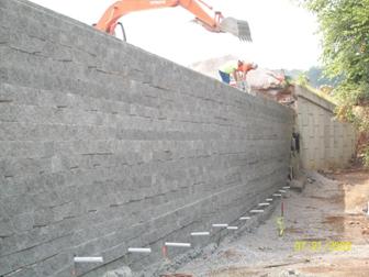
Figure 82. Photo. Use of GRS wall to repair damaged MSE wall.
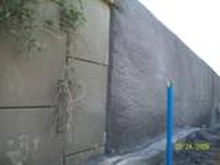
Figure 83. Photo. CMU GRS wall with a shotcrete face.
Damage to the top rows of CMU block: Figure 84 and figure 85 show a GRS wall before and
after the repair of a rock–fall impact. The repaired section is set slightly back from the original wall alignment. To repair this wall, the boulder
was removed, and each soil layer within the damaged zone was excavated. To access the fill, the fabric layers were cut perpendicular to the face and peeled
back enough to access all the reinforcement layers within the damaged zone. This process was repeated until the damaged zone was exposed. The exposed zone was
rebuilt using the 1–2–3 method explained in chapter 7, one layer at a time, from the bottom up. In areas where the reinforcement was excessively
damaged, new reinforcement was spliced in to reestablish the frictional connection. The top courses were then pinned and grouted.
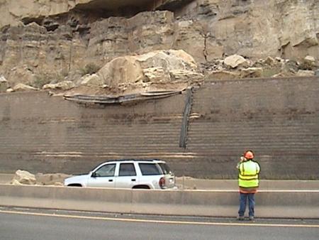
Figure 84. Photo. GRS wall damaged by large sandstone boulder.
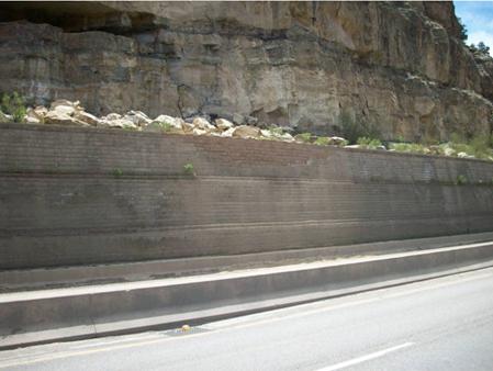
Figure 85. Photo. Repair of a GRS wall after damage caused by rock fall.
Excessive settlement of the beam seat: While this has not been observed, it is possible that the superstructure could experience
excessive movement either due to compression of the GRS abutment or external instability. If the clear space is lost and the superstructure is causing distress
to the wall, it is possible to saw a new gap to relieve the pressure. An alternative method would be to pressure grout and elevate the superstructure back to
its original grade, which may also require repair to the approach pavement.
|