

LRFD Steel Girder SuperStructure Design Example
Bolted Field Splice Design Example Design Step 4
Table of Contents
Design Step 4.1 - Obtain Design Criteria
Design Step 4.2 - Select Girder Section as Basis for Field Splice Design
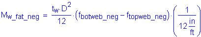
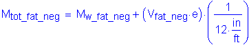
Design Step 4.3 - Compute Flange Splice Design Loads
Design Step 4.4 - Design Bottom Flange Splice
Design Step 4.5 - Design Top Flange Splice
Design Step 4.6 - Compute Web Splice Design Loads
Design Step 4.7 - Design Web Splice
Design Step 4.8 - Draw Schematic of Final Bolted Field Splice Design
Design Step 4.1 - Obtain Design Criteria
This splice design example is based on AASHTO LRFD Bridge Design Specifications (through 2002 interims). The design methods presented throughout the example are meant to be the most widely used in general bridge engineering practice.
The first design step is to identify the appropriate design criteria. This includes, but is not limited to, defining material properties, identifying relevant superstructure information, and determining the splice location.
Refer to Design Step 1 for introductory information about this design example. Additional information is presented about the design assumptions, methodology, and criteria for the entire bridge, including the splice.
Presented in Figure 4-1 is the final steel girder configuration as designed in Design Step 3. Included in Figure 4-1 is the bolted field splice location. This location was determined using the criteria presented in the narrative below.
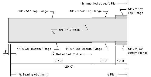
Figure 4-1 Plate Girder Elevation
The following units are defined for use in this design example:
![]()


For relatively long girders, field splices are generally required to reduce the girder shipping length. The location of the field splice is generally based on economy and includes the following considerations:
Field splices are generally located to provide girder segment lengths that do not exceed the allowable girder shipping length. The allowable girder shipping length is often a function of the shipping route from the fabrication site to the construction site.
The Specifications recommends locating splices near points of dead load contraflexure.
S6.13.6.1.4a
Field splices are generally located where total moment in the girder is relatively small. This minimizes the required splice plate thicknesses and the required number of bolts.
In Design Step 1.1, the steel properties of the girder were defined. These properties will be used for the splice plates as well.
Yield Strength: STable 6.4.1-1
Tensile Strength: For Specifications equations requiring the flange yield strength: Flange Yield Strength:
Plate Dimensions of the Left Girder (reference Design Step 3.18):
Web Thickness: Web Depth: Top Flange Width: Top Flange Thickness: Bottom Flange Width: Bottom Flange Thickness:
Plate Dimensions of the Right Girder (reference Design Step 3.18):
Web Thickness: Web Depth: Top Flange Width: Top Flange Thickness: Bottom Flange Width: Bottom Flange Thickness:
Splice Bolt Properties:
Bolt Diameter: Bolt Hole Diameter:(for design purposes) S6.13.2.5 & S6.8.3
Bolt Tensile Strength: S6.4.3.1
Concrete Deck Properties (reference Design Step 3.3):
Effective Slab Thickness: Modular Ratio: Haunch Depth (measured from top of web): Effective Flange Width:
Based on the concrete deck design example and as illustrated in Figure 2-18, the area of longitudinal deck reinforcing steel in the negative moment region is computed as follows:
For the top steel: For the bottom steel:
Resistance Factors: S6.5.4.2
Flexure: Shear: Axial Compression: Tension, fracture in net section: Tension, yielding in gross section: Bolts bearing on material: A325 and A490 bolts in shear: Block shear:
Design Step 4.2 - Select Girder Section as Basis for Field Splice Design
Where a section changes at a splice, the smaller of the two connected sections shall be used in the design. Therefore, the bolted field splice will be designed based on the left adjacent girder section properties. This will be referred to as the Left Girder throughout the calculations. The girder located to the right of the bolted field splice will be designated the Right Girder.
S6.13.6.1.1
Design Step 4.3 - Compute Flange Splice Design Loads
Girder Moments at the Splice Location:
Based on the properties defined in Design Step 3 (Steel Girder Design), any number of commercially available software programs can be used to obtain the design dead and live loads at the splice. For this design example, the AASHTO Opis software was used. A summary of the unfactored moments at the splice from the initial trial of the girder design are listed below. The live loads include impact and distribution factors.
| Loads | Moments | |
|---|---|---|
| Dead Loads: | Noncomposite: | |
| Composite: | ||
| Future Wearing Surface: | ||
| Live Loads: | HL-93 Positive: | |
| HL-93 Negative: | ||
| Fatigue Positive: | ||
| Fatigue Negative: | ||
Typically, splices are designed for the Strength I, Service II, and Fatigue Limit States. The load factors for these limit states are shown in Table 4-1:
S6.13.6
| Load Factors | ||||||
| Strength I | Service II | Fatigue | ||||
| Load | γmax | γmin | γmax | γmin | γmax | γmin |
| DC | 1.25 | 0.90 | 1.00 | 1.00 | - | - |
| DW | 1.50 | 0.65 | 1.00 | 1.00 | - | - |
| LL | 1.75 | 1.75 | 1.30 | 1.30 | 0.75 | 0.75 |
STable 3.4.1-1
STable 3.4.1-2
Table 4-1 Load Factors
Flange Stress Computation Procedure:
As previously mentioned, the applicable limit states for the splice design are Strength I, Service II, and Fatigue. The stresses corresponding to these limit states will be computed at the midthickness of the top and bottom flanges. The appropriate section properties and load factors for use in computing stresses are described below. Where necessary, refer to the signs of the previously documented design moments.
S6.13.6
Strength I Limit State:
At the strength limit state, the section properties for flexural members with holes in the tension flange shall be computed using an effective flange area.
S6.10.3.6
Case 1: Dead Load + Positive Live Load
For this case, stresses will be computed using the effective top flange area for the noncomposite dead load, and the effective bottom flange area for the composite dead load, future wearing surface, and live load. The minimum load factor is used for the DC dead loads (noncomposite and composite) and the maximum load factor is used for the future wearing surface. The composite dead load and future wearing surface act on the 3n- or the n-composite slab section, whichever gives the higher stresses, and the live load acts on the n-composite slab section.
STable 3.4.1-2
S6.10.3.1.1b
Case 2: Dead Load + Negative Live Load
For this case, stresses will be computed using the effective top flange area for all loads. The future wearing surface is excluded and the maximum load factor is used for the DC dead loads. The live load acts on the composite steel girder plus longitudinal reinforcement section. The composite dead load is applied to this section as well, as a conservative assumption for simplicity and convenience, since the net effect of the live load is to induce tension in the slab. The reinforcing steel in the deck that is used corresponds to the negative moment deck reinforcement shown in Figure 2-18.
Service II Limit State:
S6.13.6.1.4a
Case 1: Dead Load + Positive Live Load
For this case, stresses will be computed using the gross steel section. The future wearing surface is included and acts, along with the composite dead load, on the 3n- or n-composite slab section, whichever gives the higher stresses. The live load acts on the n-composite slab section.
Case 2: Dead Load + Negative Live Load
S6.10.3.1.1c
For this case, stresses will be computed using the gross steel section. The future wearing surface is excluded. The composite dead load acts on the 3n- or n-composite slab section, whichever gives the larger stresses. The live load acts on the n-composite slab section.
Fatigue Limit State:
C6.13.6.1.4a
Case 1: Positive Live Load
For this case, stresses will be computed using the gross steel section. The live load acts on the n-composite slab section.
Case 2: Negative Live Load
S6.10.3.1.1c
For this case, stresses will be computed using the gross steel section. The live load acts on the n-composite slab section.
Section Properties:
Effective Flange Areas:
S6.13.6.1.4c & S6.10.3.6
SEquation 6.10.3.6-1
For holes equal to or less than 1.25 inches in diameter:
The effective area of the bottom flange of the steel girder is as follows:

The net area of the bottom flange of the steel girder is defined as the product of the thickness of the flange and the smallest net width. The net width is determined by subtracting from the width of the flange the sum of the widths of all holes in the assumed failure chain, and then adding the quantity s2 /4g for each space between consective holes in the chain. Since the bolt holes in the flanges are lined up transverse to the loading direction, the governing failure chain is straight across the flange (i.e., s2 /4g is equal to zero).
S6.8.3
The net area of the bottom flange of the steel girder now follows:

With the gross and net areas identified, along with beta, the effective tension area of the bottom flange can now be computed as follows:
Check:
<
OK
Effective bottom flange area:
Similar calculations determine the effective tension area for the top flange of the steel girder:
Effective top flange area:
The transformed effective area of the concrete flange of the steel girder is now determined. This requires the modular ratio as follows:
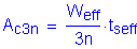
Ac= Effective Slab Width x tseff
Modular Ratio
where:
Effective Slab Width:
Modular Ratio:
For the n-composite beam:
For the 3n-composite beam:
The section properties for the Left Girder are calculated with the aid of Figure 4-2 shown below:
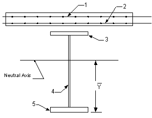
Figure 4-2 Girder, Slab and Longitudinal Reinforcement
The following tables contain the section properties for the left (i.e., smaller) girder section at the splice location. The properties in Table 4-2 are based on the gross area of the steel girder, and these properties are used for computation of stresses for the Service II and Fatigue Limit States. The properties in Tables 4-3 and 4-4 are based on the effective top flange and effective bottom flange of the steel girder, respectively, and these properties are used for computation of stresses for the Strength I Limit State.
| Gross Section Properties | ||||||
| Section | Area, A (Inches2) | Centroid, d (Inches) | A*d (Inches3) | Io(Inches4) | A*y2 (Inches4) | Itotal (Inches4) |
| Girder only: | ||||||
| Top flange | 8.750 | 55.188 | 482.9 | 0.3 | 7530.2 | 7530.5 |
| Web | 27.000 | 27.875 | 752.6 | 6561.0 | 110.5 | 6671.5 |
| Bottom flange | 12.250 | 0.438 | 5.4 | 0.8 | 7912.0 | 7912.7 |
| Total | 48.000 | 25.852 | 1240.9 | 6562.1 | 15552.7 | 22114.8 |
| Composite (3n): | ||||||
| Girder | 48.000 | 25.852 | 1240.9 | 22114.8 | 11134.4 | 33249.2 |
| Slab | 34.333 | 62.375 | 2141.5 | 183.1 | 15566.5 | 15749.6 |
| Total | 82.333 | 41.082 | 3382.4 | 22297.9 | 26700.8 | 48998.7 |
| Composite (n): | ||||||
| Girder | 48.000 | 25.852 | 1240.9 | 22114.8 | 29792.4 | 51907.2 |
| Slab | 103.000 | 62.375 | 6424.6 | 549.3 | 13883.8 | 14433.2 |
| Total | 151.000 | 50.765 | 7665.5 | 22664.1 | 43676.2 | 66340.3 |
| Section | ybotmid (Inches) | ytopmid (Inches) | Sbotweb (Inches3) | Sbotmid (Inches3) | Stopmid (Inches3) | Stopweb (Inches3) |
| Girder only | 25.414 | 29.336 | 885.4 | 870.2 | 753.8 | 762.0 |
| Composite (3n) | 40.644 | 14.106 | 1218.7 | 1205.5 | 3473.7 | 3552.4 |
| Composite (n) | 50.327 | 4.423 | 1329.7 | 1318.2 | 15000.3 | 16140.8 |
Table 4-2 Section Properties Based on Gross Steel Section
| Section Properties - Effective Top Flange Area | ||||||
| Section | Area, A (Inches2) | Centroid, d (Inches) | A*d (Inches3) | Io(Inches4) | A*y2 (Inches4) | Itotal (Inches4) |
| Girder only: | ||||||
| Top flange | 6.840 | 55.188 | 377.5 | 0.3 | 6384.5 | 6384.8 |
| Web | 27.000 | 27.875 | 752.6 | 6561.0 | 283.3 | 6844.3 |
| Bottom flange | 12.250 | 0.438 | 5.4 | 0.8 | 7173.1 | 7173.9 |
| Total | 46.090 | 24.636 | 1135.5 | 6562.1 | 13840.9 | 20402.9 |
| Deck Steel: | ||||||
| Girder | 46.090 | 24.636 | 1135.5 | 20402.9 | 3009.2 | 23412.2 |
| Top Steel | 6.386 | 63.438 | 405.1 | 0.0 | 6027.1 | 6027.1 |
| Bottom Steel | 6.386 | 60.313 | 385.2 | 0.0 | 4863.3 | 4863.3 |
| Total | 58.862 | 32.716 | 1925.7 | 20402.9 | 13899.7 | 34302.6 |
| Composite (3n): | ||||||
| Girder | 46.090 | 24.636 | 1135.5 | 20402.9 | 11963.5 | 32366.4 |
| Slab | 34.333 | 62.375 | 2141.5 | 183.1 | 16060.1 | 16243.2 |
| Total | 80.423 | 40.747 | 3277.0 | 20586.1 | 28023.6 | 48609.7 |
| Composite (n): | ||||||
| Girder | 46.090 | 24.636 | 1135.5 | 20402.9 | 31330.6 | 51733.5 |
| Slab | 103.000 | 62.375 | 6424.6 | 549.3 | 14019.7 | 14569.0 |
| Total | 149.090 | 50.708 | 7560.1 | 20952.3 | 45350.2 | 66302.5 |
| Section | ybotmid (Inches) | ytopmid (Inches) | Sbotmid (Inches3) | Stopmid (Inches3) | ||
| Girder only | 24.198 | 30.552 | 843.2 | 667.8 | ||
| Deck Steel | 32.279 | 22.471 | 1062.7 | 1526.5 | ||
| Composite (3n) | 40.309 | 14.441 | 1205.9 | 3366.2 | ||
| Composite (n) | 50.271 | 4.479 | 1318.9 | 14802.1 | ||
Table 4-3 Section Properties Using Effective Top Flange Area of Steel Girder
| Section Properties - Effective Bottom Flange Area | ||||||
| Section | Area, A (Inches2) | Centroid, d (Inches) | A*d (Inches3) | Io(Inches4) | A*y2 (Inches4) | Itotal (Inches4) |
| Girder only: | ||||||
| Top flange | 8.750 | 55.188 | 482.9 | 0.3 | 6781.3 | 6781.6 |
| Web | 27.000 | 27.875 | 752.6 | 6561.0 | 7.5 | 6568.5 |
| Bottom flange | 9.580 | 0.438 | 4.2 | 0.6 | 6937.8 | 6938.5 |
| Total | 45.330 | 27.348 | 1239.7 | 6561.9 | 13726.7 | 20288.6 |
| Deck Steel: | ||||||
| Girder | 45.330 | 27.348 | 1239.7 | 20288.6 | 2611.1 | 22899.7 |
| Top Steel | 6.386 | 63.438 | 405.1 | 0.0 | 5186.8 | 5186.8 |
| Bottom Steel | 6.386 | 60.313 | 385.2 | 0.0 | 4111.7 | 4111.7 |
| Total | 58.102 | 34.938 | 2030.0 | 20288.6 | 11909.6 | 32198.2 |
| Composite (3n): | ||||||
| Girder | 45.330 | 27.348 | 1239.7 | 20288.6 | 10329.9 | 30618.4 |
| Slab | 34.333 | 62.375 | 2141.5 | 183.1 | 13638.4 | 13821.5 |
| Total | 79.663 | 42.444 | 3381.2 | 20471.7 | 23968.3 | 44440.0 |
| Composite (n): | ||||||
| Girder | 45.330 | 27.348 | 1239.7 | 20288.6 | 26816.1 | 47104.7 |
| Slab | 103.000 | 62.375 | 6424.6 | 549.3 | 11801.7 | 12351.0 |
| Total | 148.330 | 51.671 | 7664.3 | 20837.9 | 38617.8 | 59455.7 |
| Section | ybotmid (Inches) | ytopmid (Inches) | Sbotmid (Inches3) | Stopmid (Inches3) | ||
| Girder only | 26.911 | 27.839 | 753.9 | 728.8 | ||
| Deck Steel | 34.501 | 20.249 | 933.3 | 1590.1 | ||
| Composite (3n) | 42.007 | 12.743 | 1057.9 | 3487.3 | ||
| Composite (n) | 51.233 | 3.517 | 1160.5 | 16906.8 | ||
Table 4-4 Section Properties Using Effective Bottom Flange Area of Steel Girder
Strength I Limit State Stresses - Dead Load + Positive Live Load:
The section properties for this case have been calculated in Tables 4-3 and 4-4. The stresses at the midthickness of the flanges are shown in Table 4-6, which immediately follows the sample calculation presented below.
A typical computation for the stresses occurring at the midthickness
of the flanges is presented in the example below. The stress in the bottom flange of the girder is computed using the 3n-composite section for the composite dead load and future wearing surface,
and the n-composite section for the live load:

Noncomposite DL:
Stress at the midthickness:
Noncomposite DL Moment:
Section Modulus (girder only), from Table 4-3:
Stress due to the noncomposite dead load:
Composite DL:
Stress at the midthickness:
Composite DL Moment:
Section Modulus (3n-composite), From Table 4-4:
Stress due to the composite dead load:
Future Wearing Surface:
Stress at the midthickness:
FWS Moment:
Section Modulus (3n-composite), From Table 4-4:
Stress due to the composite dead load:
Positive Live Load:
Stress at the midthickness:
Live Load Moment:
Section Modulus (n-composite), From Table 4-4:
Stress due to the positive live load:
The preceding stresses are now factored by their respective load factors to obtain the final factored stress at the midthickness of the bottom flange for this load case. The applicable load factors for this case were discussed previously.
STable 3.4.1-1 & STable 3.4.1-2
![]()
![]()
The stresses at the midthickness of the top flange for this load case are computed in a similar manner. The section properties used to obtain the stresses in the top flange are also from Tables 4-3 and 4-4.
The top and bottom flange midthickness stresses are summarized in Table 4-5, shown below.
| Strength I - Dead Load + Positive Live Load Summary of Unfactored Values |
|||
| Loading | Moment (K-ft) | fbotmid(ksi) | ftopmid(ksi) |
| Noncomposite DL | -51.80 | -0.74 | 0.93 |
| Composite DL | 15.50 | 0.18 | -0.05 |
| FWS DL | 18.80 | 0.21 | -0.06 |
| Live Load - HL-93 | 1307.80 | 13.52 | -0.93 |
| Summary of Factored Values | |||
| Limit State | |||
| Strength I | 2284.18 | 23.48 | -0.93 |
Table 4-5 Strength I Flange Stresses for Dead + Pos. LL
The computation of the midthickness flange stresses for the remaining load cases are computed in a manner similar to what was shown in the sample calculation that preceded Table 4-5.
Strength I Limit State - Dead Load + Negative Live Load:
The computed stresses in the following table require the use of section properties from Table 4-3.
| Strength I - Dead Load + Negative Live Load Summary of Unfactored Values |
|||
| Loading | Moment (K-ft) | fbotmid(ksi) | ftopmid(ksi) |
| Noncomposite DL | -51.80 | -0.74 | 0.93 |
| Composite DL | 15.50 | 0.18 | -0.12 |
| Live Load - HL-93 | -953.30 | -10.76 | 7.49 |
| Summary of Factored Values | |||
| Limit State | |||
| Strength I | -1713.65 | -19.54 | 14.13 |
Table 4-6 Strength I Flange Stresses for Dead + Neg. LL
Service II Limit State - Dead Load + Positive Live Load:
The computed stresses in the following table require the use of section properties from Table 4-2.
| Service II - Dead Load + Positive Live Load Summary of Unfactored Values |
|||
| Loading | Moment (K-ft) | fbotmid(ksi) | ftopmid(ksi) |
| Noncomposite DL | -51.80 | -0.71 | 0.82 |
| Composite DL | 15.50 | 0.15 | -0.05 |
| FWS | 18.80 | 0.19 | -0.06 |
| Live Load - HL-93 | 1307.80 | 11.91 | -1.05 |
| Summary of Factored Values | |||
| Limit State | |||
| Service II | 1682.64 | 15.10 | -0.65 |
Table 4-7 Service II Flange Stresses for Dead + Pos. LL
Service II Limit State - Dead Load + Negative Live Load:
The computed stresses in the following table require the use of section properties from Table 4-2.
| Service II - Dead Load + Negative Live Load Summary of Unfactored Values |
|||
| Loading | Moment (K-ft) | fbotmid(ksi) | ftopmid(ksi) |
| Noncomposite DL | -51.80 | -0.71 | 0.82 |
| Composite DL | 15.50 | 0.14 | -0.01 |
| Live Load - HL-93 | -953.30 | -8.68 | 0.76 |
| Summary of Factored Values | |||
| Limit State | |||
| Service II | -1275.59 | -11.85 | 1.80 |
Table 4-8 Service II Flange Stresses for Dead + Neg. LL
Fatigue Limit State - Positive Live Load:
The computed stresses in the following table require the use of section properties from Table 4-2.
| Fatigue - Positive Live Load Summary of Unfactored Values |
|||
| Loading | Moment (K-ft) | fbotmid(ksi) | ftopmid(ksi) |
| Live Load-Fatigue | 394.30 | 3.59 | -0.32 |
| Summary of Factored Values | |||
| Limit State | |||
| Fatigue | 295.73 | 2.69 | -0.24 |
Table 4-9 Fatigue Flange Stresses for Positive LL
Fatigue Limit State - Negative Live Load:
The computed stresses in the following table require the use of section properties from Table 4-2.
| Fatigue - Negative Live Load | |||
| Summary of Unfactored Values | |||
| Loading | Moment (K-ft) | fbotmid(ksi) | ftopmid(ksi) |
| Live Load-Fatigue | -284.00 | -2.59 | 0.23 |
| Summary of Factored Values | |||
| Limit State | |||
| Fatigue | -213.00 | -1.94 | 0.17 |
Table 4-10 Fatigue Flange Stresses for Negative LL
Fatigue Limit State:
The computed stresses in the following table require the use of section properties from Table 4-2.
| Fatigue - Live Load | |||
| Summary of Unfactored Values | |||
| Loading | Moment (K-ft) | fbotweb(ksi) | ftopweb(ksi) |
| Live Load-Pos | 394.3 | 3.56 | -0.29 |
| Live Load-Neg | -284.00 | -2.56 | 0.21 |
| Summary of Factored Values | |||
| Limit State | |||
| Pos Fatigue | 295.73 | 2.67 | -0.22 |
| Neg Fatigue | -213.00 | -1.92 | 0.16 |
Table 4-11 Fatigue Web Stresses for Positive and Negative Live Load
A summary of the factored stresses at the midthickness of the top and bottom flanges for the Strength I, Service II, and Fatigue limit states are presented below in Tables 4-12 through 4-14. Table 4-14 also contains the top and bottom web fatigue stresses.
| Stress (ksi) | |||
| Limit State | Location | Dead + Pos. LL | Dead + Neg. LL |
| Strength I | Bottom Flange | 23.48 | -19.54 |
| Top Flange | -0.93 | 14.13 | |
Table 4-12 Strength I Flange Stresses
| Stress (ksi) | |||
| Limit State | Location | Dead + Pos. LL | Dead + Neg. LL |
| Service II | Bottom Flange | 15.10 | -11.85 |
| Top Flange | -0.65 | 1.80 | |
Table 4-13 Service II Flange Stresses
| Stress (ksi) | |||
| Limit State | Location | Positive LL | Negative LL |
| Fatigue | Bottom Flange | 2.69 | -1.94 |
| Top Flange | -0.24 | 0.17 | |
| Bottom of Web | 2.67 | -1.92 | |
| Top of Web | -0.22 | 0.16 | |
Table 4-14 Fatigue Flange and Web Stresses
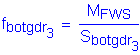
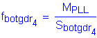
Strength I Minimum Design Force - Controlling Flange:
S6.13.6.1.4c
The next step is to determine the minimum design forces for the controlling flange of each load case (i.e., positive and negative live load). By inspection of Table 4-12, it is obvious that the bottom flange is the controlling flange for both positive and negative live load for the Strength I Limit State.
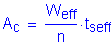
The minimum design force for the controlling flange, Pcu, is taken equal to the design stress, Fcf, times the smaller effective flange area, Ae,on either side of the splice. When a flange is in compression, the effective compression flange area shall be taken as Ae= Ag.
S6.10.3.6
The calculation of the minimum design force is presented below for the load case of dead load with positive live load.
The minimum design stress for the controlling (bottom) flange is computed as follows:
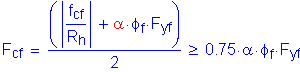
SEquation 6.13.6.1.4c-1
where:
Maximum flexural stress due to the factored loads at the midthickness of the controlling flange at the point of splice (from Table 4-12):
Hybrid girder reduction factor.
For homogeneous girders:
Flange stress reduction factor:
Resistance factor for flexure (Design Step 4.1):
Minimum yield strength of the flange:
Compute the minimum required design stress:
The minimum design stress for the bottom flange for this load case is:
The minimum design force now follows:
The gross area of the bottom flange is:
Since the bottom flange force for this load case is a tensile force, the effective area will be used. This value was computed previously to be:
Therefore:
Table 4-15 presents the minimum design forces for the Strength I Limit State for both the positive and negative live load cases.
| Strength I Limit State Controlling Flange | |||||
| Load Case | Location | fcf (ksi) | Fcf (ksi) | Area (in2) | Pcu (kips) |
| Dead + Pos. LL | Bot. Flange | 23.48 | 37.5 | 9.58 | 359.25 |
| Dead + Neg. LL | Bot. Flange | -19.54 | 37.5 | 12.25 | 459.38 |
Table 4-15 Controlling Flange Forces
In the above table, the design controlling flange force (Pcu) is a compressive force for negative live load.
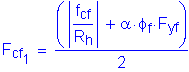
Strength I Minimum Design Force - Noncontrolling Flange:
S6.13.6.1.4c
The next step is to determine the minimum design forces for the noncontrolling flange of each load case (i.e., positive and negative live load). By inspection of Table 4-12, the top flange is the noncontrolling flange for both positive and negative live load for the Strength I Limit State.
The minimum design force for the noncontrolling flange, Pncu, is taken equal to the design stress, Fncf, times the smaller effective flange area, Ae,on either side of the splice. When a flange is in compression, the effective compression flange area shall be taken as Ae= Ag.
S6.10.3.6
The calculation of the minimum design force is presented below for the load case of dead load with positive live load.
The minimum design stress for the noncontrolling (top) flange is computed as follows:
SEquation 6.13.6.1.4c-2
where:
Maximum flexural stress due to the factored loads at the midthickness of the noncontrolling flange at the point of splice concurrent with fcf (see Table 4-12):
Controlling flange design stress:
Controlling flange actual stress:
Controlling flange stress ratio:

Hybrid girder reduction factor:
Therefore:
Compute the minimum required design stress:
The minimum design stress in the top flange is:
The minimum design force now follows:
For the positive live load case, the top flange is in compression. The effective compression flange area shall be taken as:
SEquation 6.10.3.6-2

Therefore:
(compression)
Table 4-16 presents the minimum design forces for the Strength I Limit State for both the positive and negative live load cases.
| Strength I Limit State Noncontrolling Flange | |||||
| Load Case | Location | fncf (ksi) | Fncf (ksi) | Area (in2) | Pncu (kips) |
| Dead + Pos. LL | Top Flange | -0.93 | 37.5 | 8.75 | 328.13 |
| Dead + Neg. LL | Top Flange | 14.13 | 37.5 | 6.84 | 256.50 |
Table 4-16 Noncontrolling Flange Forces
In the above table, the design noncontrolling flange force (Pncu) is a compressive force for positive live load.
Service II Limit State Flange Forces:
S6.13.6.1.4c
Per the Specifications, bolted connections for flange splices are to be designed as slip-critical connections for the service level flange design force. This design force shall be taken as the Service II design stress, Fs, multiplied by the smaller gross flange area on either side of the splice.
Fs is defined as follows:

SEquation 6.13.6.1.4c-4
fs = maximum flexural Service II stress at the midthickness of the flange under consideration.
The factored Service II design stresses and forces are shown in Table 4-17 below.
| Service II Limit State | ||||
| Load Case | Location | Fs (ksi) | Agross (in2) | Ps (kips) |
| Dead + Pos. LL | Bot. Flange | 15.10 | 12.25 | 184.98 |
| Top Flange | -0.65 | 8.75 | -5.69 | |
| Dead + Neg. LL | Bot. Flange | -11.85 | 12.25 | -145.16 |
| Top Flange | 1.80 | 8.75 | 15.75 | |
Table 4-17 Service II Flange Forces
It is important to note here that the flange slip resistance must exceed the larger of: (1) the Service II flange forces or (2) the factored flange forces from the moments at the splice due to constructibility (erection and/or deck pouring sequence). However, in this design example, no special erection procedure is prescribed and, per the Introduction in Design Step 1, the deck is placed in a single pour. Therefore, the constructibility moment is equal to the noncomposite dead load moment shown at the beginning of this design step. By inspection, the Service II Limit State will control for checking of slip-critical connections for the flanges and the web in this example.
S3.4.2
Fatigue Limit State Stresses:
C6.13.6.1.4c
The final portion of this design step is to determine the range of the stresses at the midthickness of both flanges, and at the top and bottom of the web for the Fatigue Limit State. The ranges are calculated below and presented in Table 4-18.
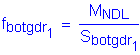
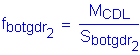
A typical calculation of the stress range for the bottom flange is shown below.
From Tables 4-9 and 4-10, the factored stresses at the midthickness of the bottom flange are:
Case 1 - Positive Live Load:
Case 2 - Negative Live Load:
The stress range is determined by:
| Fatigue Limit State Stress Range (ksi) |
|
| Location | Df (ksi) |
| Bottom Flange | 4.63 |
| Top Flange | 0.41 |
| Bottom of Web | 4.59 |
| Top of Web | 0.38 |
Table 4-18 Fatigue Stress Ranges
Design Step 4.4 - Design Bottom Flange Splice
Splice Plate Dimensions:
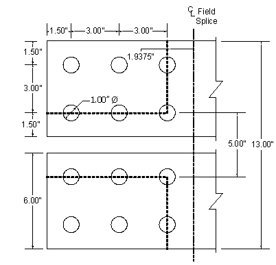
The width of the outside plate should be at least as wide as the width of the narrowest flange at the splice. Therefore, try a 7/16" x 14" outside splice plate with two 1/2" x 6" inside splice plates. Include a 1/2" x 14" fill plate on the outside. Figure 4-3 illustrates the initial bottom flange splice configuration.
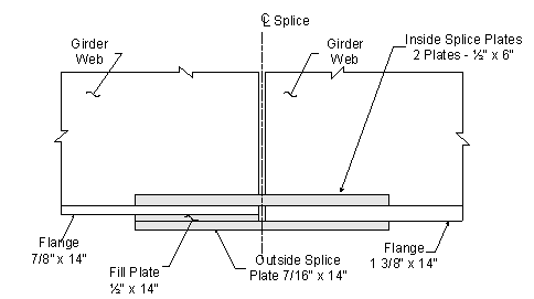
Figure 4-3 Bottom Flange Splice
The dimensions of the elements involved in the bottom flange splice from Figure 4-3 are:
Thickness of the inside splice plate:
Width of the inside splice plate:
Thickness of the outside splice plate:
Width of the outside splice plate:
Thickness of the fill plate:
Width of the fill plate:
If the combined area of the inside splice plates is within ten percent of the area of the outside splice plate, then both the inside and outside splice plates may be designed for one-half the flange design force.
C6.13.6.1.4c
Gross area of the inside and outside splice plates:
Inside:
Outside:
Check:
The combined areas are within ten percent.
If the areas of the inside and outside splice plates had differed by more than ten percent, the flange design force would be proportioned to the inside and outside splice plates. This is calculated by multiplying the flange design force by the ratio of the area of the splice plate under consideration to the total area of the inner and outer splice plates.
C6.13.6.1.4c
Yielding and Fracture of Splice Plates:
S6.13.6.1.4c
Case 1 - Tension:
S6.13.5.2
At the Strength Limit State, the design force in the splice plates subjected to tension shall not exceed the factored resistances for yielding, fracture, and block shear.
From Table 4-15, the Strength I bottom flange tension design force is:
The factored tensile resistance for yielding on the gross section is:

SEquation 6.8.2.1-1
(Design Step 4.1)
(Design Step 4.1)
For yielding of the outside splice plate:
The outside splice plate takes half of the design load:
>
OK
For yielding of the inside splice plates:
The inside splice plate takes half of the design load:
>
OK
The factored tensile resistance for fracture on the net section is:

SEquation 6.8.2.1-2
(Design Step 4.1)
(Design Step 4.1)
S6.13.5.2
To compute the net area of the splice plates, assume four 7/8" bolts across the width of the splice plate.
The net width shall be determined for each chain of holes extending across the member along any transverse, diagonal or zigzag line. This is determined by subtracting from the width of the element the sum of the width of all holes in the chain and adding the quantity s2/4g for each space between consecutive holes in the chain. For non-staggered holes, such as in this design example, the minimum net width is the width of the element minus the number of bolt holes in a line straight across the width.
S6.8.3
For fracture of the outside splice plate:
The net width is:
(Design Step 4.1)
The nominal area is determined to be:
The net area of the connecting element is limited to 0.85 Ag:
S6.13.5.2
<
OK
The outside splice plate takes half of the design flange force:
>
OK
For fracture of the inside splice plates:
The net width is:
The nominal area is determined to be:
The net area of the connecting element is limited to 0.85 Ag:
S6.13.5.2
<
OK
The inside splice plates take half of the design flange force:
>
OK
Case 2 - Compression:
S6.13.6.1.4c
From Table 4-15, the Strength I bottom flange compression design force is:
This force is distributed equally to the inside and outside splice plates.
The factored resistance of the splice plate is:

SEquation 6.13.6.1.4c-3
(Design Step 4.1)
For yielding of the outside splice plate:
>
OK
For yielding of the inside splice plates:
>
OK
Block Shear:
S6.13.6.1.4c
S6.13.5.2
S6.13.4
All tension connections, including connection plates, splice plates and gusset plates, shall be investigated to ensure that adequate connection material is provided to develop the factored resistance of the connection. Block shear rupture will usually not govern the design of splice plates of typical proportion. However, the block shear checks are carried out here for completeness.
From Table 4-15, the Strength I bottom flange tension design force is:
To determine the appropriate block shear equation:
If
then:
SEquation 6.13.4-1
Otherwise:
SEquation 6.13.4-2
where, from Design Step 4.1:
Minimum yield strength of the connected material:
Minimum tensile strength of the connected material:
Resistance factor for block shear:
Outside Splice Plate:
Failure Mode 1:
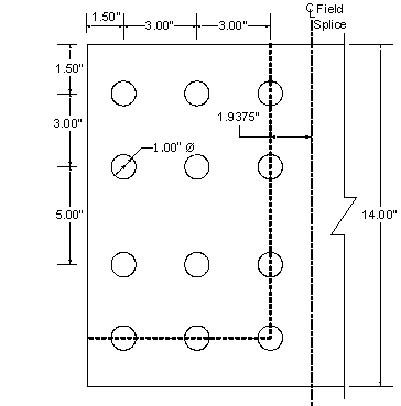
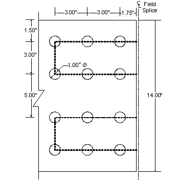
A bolt pattern must be assumed prior to checking an assumed block shear failure mode. An initial bolt pattern for the bottom flange splice, along with the first assumed failure mode, is shown in Figure 4-4. The outside splice plate will now be checked for block shear.
Figure 4-4 Outside Splice Plate - Failure Mode 1
Applying the factored resistance equations presented previously to the outside splice plate for Failure Mode 1:
Gross area along the plane resisting shear stress:
Net area along the plane resisting shear stress:
Gross area along the plane resisting tension stress:
Net area along the plane resisting tension stress:
To determine which equation should be applied to calculate the factored resistance:
>
Therefore, use SEquation 6.13.4-1:
Check:
>
OK
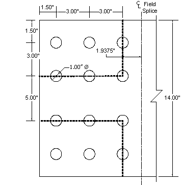
Failure Mode 2:
See Figure 4-5 for Failure Mode 2:
Figure 4-5 Outside Splice Plate - Failure Mode 2
Applying the factored resistance equations presented previously to the outside splice plate for Failure Mode 2:
Gross area along the plane resisting shear stress:
Net area along the plane resisting shear stress:
Gross area along the plane resisting tension stress:
Net area along the plane resisting tension stress:
To determine which equation should be applied to calculate the factored resistance:
>
Therefore, use SEquation 6.13.4-1:
Check:
>
OK
Inside Splice Plates:
The inside splice plates will now be checked for block shear. See Figure 4-6 for the assumed failure mode:
Figure 4-6 Inside Splice Plates - Block Shear Check
Applying the factored resistance equations presented previously to the inside splice plates for the assumed failure mode:
Gross area along the plane resisting shear stress:
Net area along the plane resisting shear stress:
Gross area along the plane resisting tension stress:
Net area along the plane resisting tension stress:
To determine which equation should be applied to calculate the factored resistance:
>
Therefore, use SEquation 6.13.4-1:
Check:
>
OK
Girder Bottom Flange:
The girder bottom flange will now be checked for block shear. See Figure 4-7 for the assumed failure mode:
Figure 4-7 Bottom Flange - Block Shear Check
Applying the factored resistance equations presented previously to the bottom flange for the assumed failure mode:
Gross area along the plane resisting shear stress:
Net area along the plane resisting shear stress:
Gross area along the plane resisting tension stress:
Net area along the plane resisting tension stress:
To determine which equation should be applied to calculate the factored resistance:
<
Therefore, use SEquation 6.13.4-2:
Check:
>
OK
It should be noted that although the block shear checks performed in this design example indicate an overdesign, the number of bolts cannot be reduced prior to checking shear on the bolts and bearing at the bolt holes. These checks are performed in what follows.
Flange Bolts - Shear:
Determine the number of bolts for the bottom flange splice plates that are required to develop the Strength I design force in the flange in shear assuming the bolts in the connection have slipped and gone into bearing. A minimum of two rows of bolts should be provided to ensure proper alignment and stability of the girder during construction.
The Strength I flange design force used in this check was previously computed (reference Table 4-15):
The factored resistance of an ASTM A325 7/8" diameter high-strength bolt in shear must be determined, assuming the threads are excluded from the shear planes. For this case, the number of bolts required to provide adequate shear strength is determined by assuming the design force acts on two shear planes, known as double shear.
The nominal shear resistance is computed first as follows:

SEquation 6.13.2.7-1
where:
Area of the bolt corresponding to the nominal diameter:
Specified minimum tensile strength of the bolt from Design Step 4.1:
Number of shear planes per bolt:
The factored shear resistance now follows:
(Design Step 4.1)
When bolts carrying loads pass through fillers 0.25 inches or more in thickness in axially loaded connections, including girder flange splices, either:
S6.13.6.1.5
The fillers shall be extended beyond the gusset or splice material and shall be secured by enough additional bolts to distribute the total stress in the member uniformly over the combined section of the member and the filler.
or
The fillers need not be extended and developed provided that the factored resistance of the bolts in shear at the Strength Limit State, specified in Article 6.13.2.2, is reduced by an appropriate factor:
In this design example, the reduction factor approach will be used. The reduction factor per the Specifications is:
SEquation 6.13.6.1.5-1
where:
Sum of the area of the fillers on the top and bottom of the connected plate:
The smaller of either the connected plate area (i.e., girder flange) or the sum of the splice plate areas on the top and bottom of the connected plate determines Ap.
Bottom flange area:
Sum of splice plate areas is equal to the gross areas of the inside and outside splice plates:

The minimum of the areas is:
Therefore:

The reduction factor is determined to be:
To determine the total number of bolts required for the bottom flange splice, divide the applied Strength I flange design force by the reduced allowable bolt shear strength:
The number of bolts required per side is:

The minimum number of bolts required on each side of the splice to resist the maximum Strength I flange design force in shear is twelve.
Flange Bolts - Slip Resistance:
Bolted connections for flange splices shall be designed as slip-critical connections for the Service II flange design force, or the flange design force from constructibility, whichever governs. In this design example, the Service II flange force controls (see previous discussion in Design Step 4.3).
S 6.13.6.1.4c
When checking for slip of the bolted connection for a flange splice with inner and outer splice plates, the slip resistance should always be determined by dividing the flange design force equally to the two slip planes regardless of the ratio of the splice plate areas. Slip of the connection cannot occur unless slip occurs on both planes.
C6.13.6.1.4c
From Table 4-17, the Service II bottom flange design force is:
The factored resistance for slip-critical connections is:
SEquation 6.13.2.2-1
SEquation 6.13.2.8-1
Determine the factored resistance per bolt assuming a Class B surface condition for the faying surface, standard holes (which are required per S6.13.6.1.4a) and two slip planes per bolt:
Class B surfaces are unpainted blast-cleaned surfaces and blast-cleaned surfaces with Class B coatings.
S6.13.2.8
Additionally:
Number of slip planes per bolt:
Minimum required bolt tension:
STable 6.13.2.8-1
Hole size factor:
STable 6.13.2.8-2
Surface condition factor for Class B surface conditions:
STable 6.13.2.8-3

The minimum number of bolts required to prevent slip is:

Use:
bolts < N = 12 bolts determined previously to satisfy the bolt shear requirements.
Therefore, the number of bolts required for the bottom-flange splice is controlled by the bolt shear requirements. Arrange the bolts in three rows of four bolts per line with no stagger.
 |
Friction Coefficient Selection Weathering steel can be blasted for a Class B surface. Also, for painted steel, most inorganic zinc (IOZ) primers provide a Class B surface. |
Flange Bolts - Minimum Spacing:
S6.13.2.6.1
The minimum spacing between centers of bolts in standard holes shall be no less than three times the diameter of the bolt.
(Design Step 4.1)
For this example, ![]() (see Figures 4-4 thru 4-7)
(see Figures 4-4 thru 4-7)
The minimum spacing requirement is satisfied.
Flange Bolts - Maximum Spacing for Sealing:
S6.13.2.6.2
The maximum spacing of the bolts is limited to prevent penetration of moisture in the joints.
For a single line adjacent to a free edge of an outside plate or shape (for example, the bolts along the edges of the plate parallel to the direction of the applied force):
where:
Thickness of the thinner outside plate or shape:
Maximum spacing for sealing:

OK
Next, check for sealing along the free edge at the end of the splice plate. The bolts are not staggered, therefore the applicable equation is:
Maximum spacing along the free edge at the end of the splice plate (see Figures 4-4 thru 4-7):
Maximum spacing for sealing:
OK
Therefore the requirement is satisfied.
Flange Bolts - Maximum Pitch for Stitch Bolts:
S6.13.2.6.3
The maximum pitch requirements are applicable only for mechanically fastened built-up members and will not be applied in this example.
Flange Bolts - Edge Distance:
S6.13.2.6.6
Minimum:
The minimum required edge distance is measured as the distance from the center of any bolt in a standard hole to an edge of the plate.
For a 7/8" diameter bolt measured to a sheared edge, the minimum edge distance is 1 1/2".
STable 6.13.2.6.6-1
Referring to Figures 4-4 thru 4-7, it is clear that the minimum edge distance specified for this example is 1 1/2" and thus satisfies the minimum requirement.
Maximum:
The maximum edge distance shall not be more than eight times the thickness of the thinnest outside plate or five inches.
where:
The maximum edge distance allowable is:
The maximum distance from the corner bolts to the corner of the splice plate or girder flange is equal to (reference Figure 4-7):
and satisfies the maximum edge distance requirement.
OK
Flange Bolts - Bearing at Bolt Holes:
S6.13.2.9
Check bearing of the bolts on the connected material under the maximum Strength I Limit State design force. The maximum Strength I bottom flange design force from Table 4-15 is:
The design bearing strength of the connected material is calculated as the sum of the bearing strengths of the individual bolt holes parallel to the line of the applied force.
The element of the bottom flange splice that controls the bearing check in this design example is the outer splice plate.
To determine the applicable equation for the calculation of the nominal resistance, the clear distance between holes and the clear end distance must be calculated and compared to the value of two times the nominal diameter of the bolt. This check yields:
(Design Step 4.1)
For the bolts adjacent to the end of the splice plate, the edge distance is 1 1/2". Therefore, the clear end distance between the edge of the hole and the end of the splice plate:
(Design Step 4.1)
The center-to-center distance between bolts in the direction of the force is three inches. Therefore, the clear distance between edges of adjacent holes is computed as:
For standard holes, where either the clear distance between holes or the clear end distance is less than twice the bolt diameter:
SEquation 6.13.2.9-2
For the outside splice plate:
Thickness of the connected material:
Tensile strength of the connected material (Design Step 4.1):
The nominal resistance for the end row of bolt holes is computed as follows:
The nominal resistance for the remaining bolt holes is computed as follows:
The total nominal resistance of the bolt holes is:
(Design Step 4.1)
Check:
<
OK
Fatigue of Splice Plates:
S6.6.1
Check the fatigue stresses in the base metal of the bottom flange splice plates adjacent to the slip-critical connections. Fatigue normally does not govern the design of the splice plates, and therefore, an explicit check is not specified. However, a fatigue check of the splice plates is recommended whenever the combined area of the inside and outside flange splice plates is less than the area of the smaller flange at the splice.
From Table 4-18, the factored fatigue stress range at the midthickness of the bottom flange is:
For load-induced fatigue considerations, each detail shall satisfy:
SEquation 6.6.1.2.2-1
where:
Load factor for the fatigue load combination:
Force effect, live load stress range due to the passage of the fatigue load:
Nominal fatigue resistance:

SEquation 6.6.1.2.5-1
The fatigue detail category under the condition of Mechanically Fastened Connections for checking the base metal at the gross section of high-strength bolted slip-resistant connections is Category B.
STable 6.6.1.2.3-1
The parameters required for the determination of the nominal fatigue resistance are as follows: ![]()
SEquation 6.6.1.2.5-2
For Fatigue Category B: ![]()
STable 6.6.1.2.5-1
For a span length greater than 40.0 feet and at a location near the interior support, the number of stress range cycles per truck passage: ![]()
STable 6.6.1.2.5-2
Single-lane ADTT, from Design Step 3.1: ![]()
Constant-amplitude fatigue threshold: ![]()
STable 6.6.1.2.5-3
Therefore:
![]()
Determine the nominal fatigue resistance:
Condition 1:

Condition 2:
(governs)
Check that the following is satisfied:
<
OK
Control of Permanent Deflection - Splice Plates:
S6.10.5.2
A check of the flexural stresses in the splice plates at the Service II Limit State is not explicitly specified in the specifications. However, whenever the combined area of the inside and outside flange splice plates is less than the area of the smaller flange at the splice (which is the case for the bottom flange splice in this example), such a check is recommended.
The maximum Service II flange force in the bottom flange is taken from Table 4-17:
The following criteria will be used to make this check. The equation presented is for both steel flanges of composite section:
SEquation 6.10.5.2-1
where:
Elastic flange stress caused by the factored loading:
Specified minimum yield strength of the flange (Design Step 4.1):
The flange force is equally distributed to the inner and outer splice plates due to the areas of the flanges being within 10 percent of each other:

The resulting stress in the outside splice plate is:

<
OK
The resulting stress in the inside splice plates is:
<
OK
Design Step 4.5 - Design Top Flange Splice
The design of the top flange splice is not included in this design example (for the sake of simplicity and brevity). However, the top flange splice is designed using the same procedures and methods presented in this design example for the bottom flange splice.
Design Step 4.6 - Compute Web Splice Design Loads
S6.13.6.1.4b
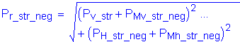
Web splice plates and their connections shall be designed for shear, the moment due to the eccentricity of the shear at the point of splice, and the portion of the flexural moment assumed to be resisted by the web at the point of the splice.
Girder Shear Forces at the Splice Location:
Based on the girder properties defined in Design Step 3 (Steel Girder Design), any number of commercially available software programs can be used to obtain the design dead and live loads at the splice. For this design example, the AASHTO Opis software was used. A summary of the unfactored shears at the splice from the initial trial of the girder design are listed below. The live loads include impact and distribution factors.
| Loads | Shears | |
|---|---|---|
| Dead Loads: | Noncomposite: | |
| Composite: | ||
| Future Wearing Surface: | ||
| Live Loads: | HL-93 Positive: | |
| HL-93 Negative: | ||
| Fatigue Positive: | ||
| Fatigue Negative: | ||
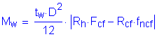
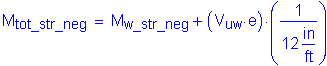
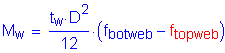
Web Moments and Horizontal Force Resultant:
C6.13.6.1.4b
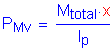
Because the portion of the flexural moment assumed to be resisted by the web is to be applied at the mid-depth of the web, a horizontal design force resultant, Huw, must also be applied at the mid-depth of the web to maintain equilibrium. The web moment and horizontal force resultant are applied together to yield a combined stress distribution equivalent to the unsymmetrical stress distribution in the web. For sections with equal compressive and tensile stresses at the top and bottom of the web (i.e., with the neutral axis located at the mid-depth of the web), Huw will equal zero.
In the computation of the portion of the flexural moment assumed to be resisted by the web, Muw, and the horizontal design force resultant, Huw, in the web, the flange stresses at the midthickness of the flanges are conservatively used. This allows use of the same stress values for both the flange and web splices, which simplifies the calculations. It is important to note that the flange stresses are taken as signed quantities in determining Muw and Huw (positive for tension; negative for compression).
C6.13.6.1.4b
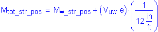
The moment, Muv, due to the eccentricity of the design shear, Vuw, is resisted solely by the web and always acts about the mid-depth of the web (i.e., horizontal force resultant is zero). This moment is computed as:

where e is defined as the distance from the centerline of the splice to the centroid of the connection on the side of the joint under consideration. For this design example:
S6.13.6.1.4b
(Reference Figure 4-8)
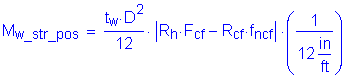
The total web moment for each load case is computed as follows:
In general, and in this example, the web splice is designed under the conservative assumption that the maximum moment and shear at the splice will occur under the same loading condition.
Strength I Limit State:
Design Shear:
S6.13.6.1.4b
For the Strength I Limit State, the girder web factored shear resistance is required when determining the design shear. Assume an unstiffened web at the splice location.
S6.10.7.2
(Design Step 4.1)
SEquation 6.10.7.1-1
SEquation 6.10.7.2-1
SEquation 6.10.7.2-2
where:
Ratio of shear buckling stress to the shear yield strength, C, is dependent upon the ratio of D/tw in comparison to:
S6.10.7.3.3a
and
And:
S6.10.7.2
Modulus of Elasticity:
Specified minimum yield strength of the web (Design Step 4.1):
From Figure 4-1:
Web Depth:
Thickness of the web:
Compare:
to the values for:
and
Based on the computed value of D/tw, use the following equation to determine C:
SEquation 6.10.7.3.3a-7
The nominal shear resistance is computed as follows:
The factored shear resistance now follows:
At the strength limit state, the design shear, Vuw, shall be taken as:
If Vu < 0.5 Vr, then:
SEquation 6.13.6.1.4b-1
Otherwise:
SEquation 6.13.6.1.4b-2
The shear due to the Strength I loading at the point of splice, Vu, is computed from the girder shear forces at the splice location listed at the beginning of this design step.
For the Strength I Limit State, the factored shear for the positive live load is:
For the Strength I Limit State, the factored shear for the negative live load is:
(controls)
Therefore:
Since Vu exceeds one-half of Vr:
SEquation 6.13.6.1.4b-2
Web Moments and Horizontal Force Resultants:
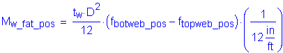
Case 1 - Dead Load + Positive Live Load:
For the loading condition with positive live load, the controlling flange was previously determined to be the bottom flange. The maximum elastic flexural stress due to the factored loads at the midthickness of the controlling flange, fcf, and the design stress for the controlling flange, Fcf,were previously computed for this loading condition. From Table 4-15:
For the same loading condition, the concurrent flexural stress at the midthickness of the noncontrolling (top) flange, fncu, was previously computed. From Table 4-16:
Therefore, the portion of the flexural moment assumed to be resisted by the web is computed as:
CEquation 6.13.6.1.4b-1
where:
The hybrid girder reduction factor:
The ratio Rcf is computed as follows:

Web thickness:
Web depth:
Compute the portion of the flexural moment to be resisted by the web:
The total web moment is:

Compute the horizontal force resultant (the variables included in this equation are as defined for Mw_str_pos):
CEquation 6.13.6.1.4b-2
The above value is a signed quantity, positive for tension and negative for compression.
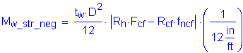
Case 2 - Dead Load + Negative Live Load:
Similarly, for the loading condition with negative live load, the controlling flange was determined to be the bottom flange. For this case the stresses were previously computed. From Table 4-15:
For the noncontrolling (top) flange, the flexural stress at the midthickness of the flange, from Table 4-16:
The ratio, Rcf, is computed as follows:

Therefore:
The total web moment is:

Compute the horizontal force resultant:
The above value is a signed quantity, positive for tension, and negative for compression.
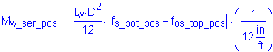
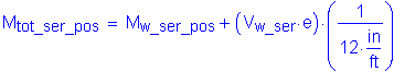
Service II Limit State:
Design Shear:
As a minimum, for checking slip of the web splice bolts, the design shear shall be taken as the shear at the point of splice under the Service II Limit State, or the shear from constructibility, whichever governs. In this design example, the Service II shear controls (see previous discussion in Design Step 4.3).
S6.13.6.1.4b
The elastic shears due to the unfactored loads at the point of the splice are listed at the beginning of this design step.
For the Service II Limit State, the factored shear for the positive live load is (ignore future wearing surface):
For the Service II Limit State, the factored shear for the negative live load is (include future wearing surface):
(governs)
Therefore:
Web Moments and Horizontal Force Resultants:
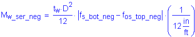
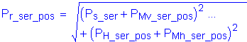
The web design moment and horizontal force resultant are computed using CEquation 6.13.6.1.4b-1 and CEquation 6.13.6.1.4b-2, modified for the Service II Limit State as follows:
C6.13.6.1.4b
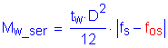
In the above equations, fs is the maximum Service II midthickness flange stress for the load case considered (i.e., positive or negative live load). The Service II midthickness flange stress in the other flange, concurrent with fs, is termed fos.
Case 1 - Dead Load + Positive Live Load:
The maximum midthickness flange flexural stress for the load case with positive live load moment for the Service II Limit State occurs in the bottom flange. From Table 4-13:
Therefore, for the load case of positive live load:
The total web moment is:

Compute the horizontal force resultant:
The above value is a signed quantity, positive for tension, and negative for compression.
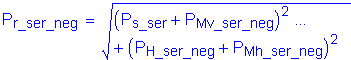
Case 2 - Dead Load + Negative Live Load:
The maximum midthickness flange flexural stress for the load case with negative live load moment for the Service II Limit State occurs in the bottom flange. From Table 4-13:
Therefore:
The total web moment is:

Compute the horizontal force resultant:
The above value is a signed quantity, positive for tension, and negative for compression.

Fatigue Limit State:
Fatigue of the base metal adjacent to the slip-critical connections in the splice plates may be checked as specified in STable 6.6.1.2.3-1 using the gross section of the splice plates and member. However, the areas of the web splice plates will often equal or exceed the area of the web to which it is attached (the case in this design example). Therefore, fatigue will generally not govern the design of the splice plates, but is carried out in this example for completeness.
C6.13.6.1.4a
Design Shear:
For the Fatigue Limit State, the factored shear for the positive live load is:
For the Fatigue Limit State, the factored shear for the negative live load is:
Web Moments and Horizontal Force Resultants:
The portion of the flexural moment to be resisted by the web and the horizontal force resultant are computed from equations similar to CEquations 6.13.6.1.4b-1 and 6.13.6.1.4b-2, respectively, with appropriate substitutions of the stresses in the web caused by the fatigue-load moment for the flange stresses in the equations. Also, the absolute value signs are removed to keep track of the signs. This yields the following equations:
Case 1 - Positive Live Load:
The factored stresses due to the positive live load moment for the Fatigue Limit State at the top and bottom of the web, from Table 4-14, are:
Therefore:
The total web moment is:

Compute the horizontal force resultant:
The above value is a signed quantity, positive for tension, and negative for compression.
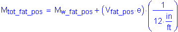
Case 2 - Negative Live Load:
The factored stresses due to the negative live load moment for the Fatigue Limit State at the top and bottom of the web, from Table 4-14, are:
Therefore:
The total web moment is:

Compute the horizontal force resultant:
The above value is a signed quantity, positive for tension, and negative for compression.
Design Step 4.7 - Design Web Splice
Web Splice Configuration:
Two vertical rows of bolts with sixteen bolts per row will be investigated. The typical bolt spacings, both horizontally and vertically, are as shown in Figure 4-8. The outermost rows of bolts are located 4 1/2" from the flanges to provide clearance for assembly (see the AISC Manual of Steel Construction for required bolt assembly clearances). The web is spliced symmetrically by plates on each side with a thickness not less than one-half the thickness of the web. Assume 5/16" x 48" splice plates on each side of the web. No web fill plate is necessary for this example.
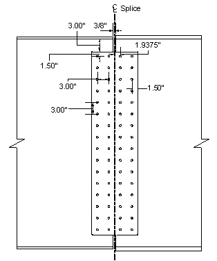
Figure 4-8 Web Splice
 |
Web Splice Design It is recommended to extend the web splice plates as near as practical to the full depth of the web between flanges without impinging on bolt assembly clearances. Also, two vertical rows of bolts in the web on each side of the splice is considered a standard minimum. This may result in an overdesigned web splice, but is considered good engineering practice. |
Web Bolts - Minimum Spacing:
S6.13.2.6.1
This check is only dependent upon the bolt diameter, and is therefore satisfied for a three inch spacing per the check for the flange bolts from Design Step 4.4.
Web Bolts - Maximum Spacing for Sealing:
S6.13.2.6.2
The maximum spacing of the bolts is limited to prevent penetration of moisture in the joints.
For a single line adjacent to a free edge of an outside plate or shape (for example, the bolts along the edges of the plate parallel to the direction of the applied force):
where:
Thickness of the thinner outside plate or shape, in this case the web plate:
Maximum spacing for sealing:

OK
S6.13.2.6.3
Web Bolts - Maximum Pitch for Stitch Bolts:
The maximum pitch requirements are applicable only for mechanically fastened built-up members and will not be applied in this example.
Web Bolts - Edge Distance:
S6.13.2.6.6
Minimum:
The minimum required edge distance is measured as the distance from the center of any bolt in a standard hole to an edge of the plate.
For a 7/8" diameter bolt measured to a sheared edge, the minimum edge distance is 1 1/2".
STable 6.13.2.6.6-1
Referring to Figure 4-8, it is clear that the minimum edge distance specified for this example is 1 1/2" and thus satisfies the minimum requirement.
Maximum:
The maximum edge distance shall not be more than eight times the thickness of the thinnest outside plate or five inches.
where:
The maximum edge distance allowable is:
The maximum distance from the corner bolts to the corner of the splice plate or girder flange is equal to (reference Figure 4-8):
and satisfies the maximum edge distance requirement.
OK
Web Bolts - Shear:
Calculate the polar moment of inertia, Ip, of the bolt group on each side of the centerline with respect to the centroid of the connection. This is required for determination of the shear force in a given bolt due to the applied web moments.
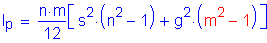
CEquation 6.13.6.1.4b-3
where:
Number of vertical rows of bolts:
Number of bolts in one vertical row:
Vertical pitch:
Horizontal pitch:
The polar moment of inertia is:
The total number of web bolts on each side of the splice, assuming two vertical rows per side with sixteen bolts per row, is:
Strength I Limit State:
Under the most critical combination of the minimum design shear, moment and horizontal force, it is assumed that the bolts in the web splice have slipped and gone into bearing. The shear strength of an ASTM A325 7/8" diameter high-strength bolt in double shear, assuming the threads are excluded from the shear planes, was computed in Design Step 4.4 for Flange Bolts - Shear:
 |
Threads in the Shear Plane |
Case 1 - Dead Load + Positive Live Load:
The following forces were computed in Design Step 4.6:
The vertical shear force in the bolts due to the applied shear force:
The horizontal shear force in the bolts due to the horizontal force resultant:
Determine the horizontal and vertical components of the bolt shear force on the extreme bolt due to the total moment in the web:
and
For the vertical component:

For the horizontal component:

Calculating the components:
The resultant bolt force for the extreme bolt is:

Case 2 - Dead Load + Negative Live Load:
The following forces were computed in Design Step 4.6:
The vertical shear force in the bolts due to the applied shear force:
The horizontal shear force in the bolts due to the horizontal force resultant:
Determine the horizontal and vertical components of the bolt shear force on the extreme bolt due to the total moment in the web:
Calculating the components:
The resultant bolt force is:
The governing resultant bolt force is:
Check:
<
OK
Service II Limit State:
The factored slip resistance, Rr, for a 7/8" diameter high-strength bolt in double shear for a Class B surface and standard holes was determined from Design Step 4.4 to be:
Case 1 - Dead Load + Positive Live Load:
The following forces were computed in Design Step 4.6:
The vertical shear force in the bolts due to the applied shear force:
The horizontal shear force in the bolts due to the horizontal force resultant:
Determine the horizontal and vertical components of the bolt shear force on the extreme bolt due to the total moment in the web:
For the vertical component:
For the horizontal component:
The resultant bolt force is:
Case 2 - Dead Load + Negative Live Load:
The following forces were computed in Design Step 4.6:
The vertical shear force in the bolts due to the applied shear force:
The horizontal shear force in the bolts due to the horizontal force resultant:
Determine the horizontal and vertical components of the bolt shear force on the extreme bolt due to the total moment in the web:
For the vertical component:
For the horizontal component:
The resultant bolt force is:
The governing resultant bolt force is:
Check:
<
OK
Thirty-two 7/8" diameter high-strength bolts in two vertical rows on each side of the splice provides sufficient resistance against bolt shear and slip.
Shear Yielding of Splice Plates:
S6.13.6.1.4b
Check for shear yielding on the gross section of the web splice plates under the Strength I design shear force, Vuw:
The factored resistance of the splice plates is taken as:
SEquation 6.13.5.3-1
SEquation 6.13.5.3-2
The gross area of the web splice is calculated as follows:
Number of splice plates:
Thickness of plate:
Depth of splice plate:
From Design Step 4.1:
Specified minimum yield strength of the connection element:
Resistance factor for shear:
The factored shear resistance is then:
Check:
<
OK
Fracture and Block Shear Rupture of the Web Splice Plates:
S6.13.6.1.4b
Strength I Limit State checks for fracture on the net section of web splice plates and block shear rupture normally do not govern for plates of typical proportion. These checks are provided in this example for completeness.
From Design Step 4.6, the factored design shear for the Strength I Limit State was determined to be:
Fracture on the Net Section:
C6.13.4
Investigation of critical sections and failure modes, other than block shear, is recommended, including the case of a net section extending across the full plate width, and, therefore, having no parallel planes. This may be a more severe requirement for a girder flange or splice plate than the block shear rupture mode.
For this case, the areas of the plate resisting tension are considered to be zero.
Therefore, the factored resistance is:
SEquation 6.13.4-2
(Design Step 4.1)
where the net area resisting shear:

Number of web plates:
Depth of the web plate:
Number of bolts along one plane:
Thickness of the web plate:
From Design Step 4.1:
Specified minimum yield strength of the connected material:
Specified minimum tensile strength of the connected material:
Diameter of the bolt holes:
Net area resisting shear:
Avn of the splice plates to be used in calculating the fracture strength of the splice plates cannot exceed eighty-five percent of the gross area of the plates:
S6.13.5.2
>
OK
The factored resistance is then:
>
OK
Block Shear Rupture Resistance:
S6.13.4
Connection plates, splice plates and gusset plates shall be investigated to ensure that adequate connection material is provided to develop the factored resistance of the connection.
Determine the applicable equation:
If
then:
SEquation 6.13.4-1
otherwise:
SEquation 6.13.4-2
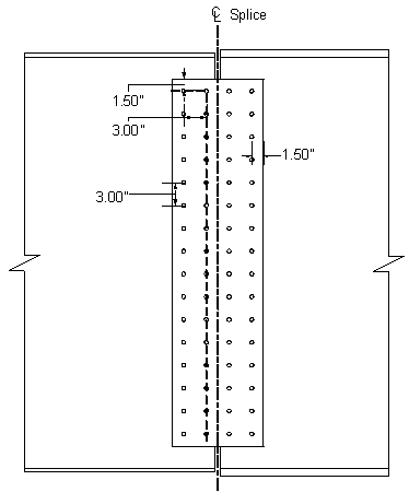
Figure 4-9 Block Shear Failure Mode - Web Splice Plate
Gross area along the plane resisting shear stress:
Net area along the plane resisting shear stress:
Gross area along the plane resisting tension stress:
Net area along the plane resisting tension stress:
Identify the appropriate block shear equation:
<
Therefore, SEquation 6.13.4-2 is the governing equation:
Check:
<
OK
Flexural Yielding of Splice Plates:
S6.13.6.1.4b
Check for flexural yielding on the gross section of the web splice plates for the Strength I Limit State due to the total web moment and the horizontal force resultant:
![]()
where:
Resistance factor for flexure (Design Step 4.1):
Section modulus of the web splice plate:
Case 1 - Dead Load + Positive Live Load:
<
OK
Case 2 - Dead Load + Negative Live Load:
<
OK
Control of Permanent Deflection - Splice Plates:
S6.10.5.2
Check the maximum normal stress on the gross section of the web splice plates for the Service II Limit State due to the total web moment and horizontal force resultant:
where:
Case 1 - Dead Load + Positive Live Load:
<
OK
Case 2 - Dead Load + Negative Live Load:
<
OK
Web Bolts - Bearing Resistance at Bolt Holes:
S6.13.2.9
Since the girder web thickness is less than twice the thickness of the web splice plates, the girder web will control for the bearing check.
Check the bearing of the bolts on the connected material for the Strength I Limit State assuming the bolts have slipped and gone into bearing. The design bearing strength of the girder web at the location of the extreme bolt in the splice is computed as the minimum resistance along the two orthogonal shear failure planes shown in Figure 4-10. The maximum force (vector resultant) acting on the extreme bolt is compared to this calculated strength, which is conservative since the components of this force parallel to the failure surfaces are smaller than the maximum force.
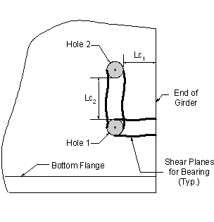
Figure 4-10 Bearing Resistance - Girder Web
To determine the applicable equation for the calculation of the nominal bearing resistance, the clear distance between holes and the clear end distance must be calculated and compared to the value of two times the nominal diameter of the bolt. This check yields:
S6.13.2.9
(Design Step 4.1)
The edge distance from the center of the hole to the edge of the girder is taken as 1.75". Therefore, the clear distance between the edge of the hole and the edge of the girder is computed as follows:
S6.13.2.6.6
(Design Step 4.1)
The center-to-center distance between adjacent holes is 3". Therefore, the clear distance between holes is:
For standard holes, where either the clear distance between holes is less than 2.0d, or the clear end distance is less than 2.0d:
SEquation 6.13.2.9-2
From Design Step 4.1:
Thickness of the connected material:
Tensile strength of the connected material:
The nominal bearing resistance at the extreme bolt hole is as follows:
The factored bearing resistance is:
(Design Step 4.1)
The controlling minimum Strength I resultant bolt force was previously computed:
<
OK
 |
Bearing Resistance at Web Bolt Holes |
Fatigue of Splice Plates:
For load-induced fatigue considerations, each detail shall satisfy:
SEquation 6.6.1.2.2-1
Fatigue is checked at the bottom edge of the splice plates, which by inspection are subject to a net tensile stress.
The normal stresses at the bottom edge of the splice plates due to the total positive and negative fatigue-load web moments and the corresponding horizontal force resultants are as follows:
From previous calculations:
Case 1 - Positive Live Load:
From Design Step 4.6:
Case 2 - Negative Live Load:
From Design Step 4.6:
The total fatigue-load stress range at the bottom edge of the web splice plates is therefore:
From Design Step 4.4, the fatigue resistance was determined as:
The fatigue check is now completed as follows:
<
OK
Design Step 4.8 - Draw Schematic of Final Bolted Field Splice Design
Figure 4-11 shows the final bolted field splice as determined in this design example.
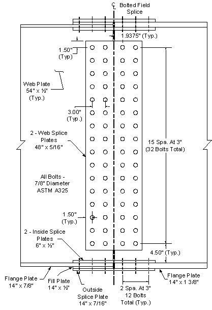
Figure 4-11 Final Bolted Field Splice Design
| << previous | Contents | next >> |