In Chapter 2 it was determined that the first step in increasing Noise Reduction in many cases would be the closing of windows and sealing of infiltration cracks. Eliminating infiltration of outside air and natural ventilation through open windows, however, necessitates the use of mechanical ventilation equipment that introduces additional noise. This must be considered when determining building modifications necessary to meet interior Design Noise Levels. Central air conditioners, such as unitary roof-mounted or stand-alone outdoor types, operate through interior ducting and can cause A-weighted interior noise levels as high as 60 dB a few feet from duct outlet diffusers. Measurements have shown that the much simpler window type air conditioner, which will provide adequate ventilation for a limited number of rooms, can generate interior noise levels as high as 62 dB. Table 12 indicates that the noise level introduced by a new ventilating system must be at least 10 dB below the non-ventilated level in order not to cause a significant increase of total noise in the building.
| When two decibel values differ by | Add the following amount to the higher value |
|---|---|
| 0 or 1 dB | 3 dB |
| 2 or 3 dB | 2 dB |
| 4 or 9 dB | 1 dB |
| 10 dB or more | 0 dB |
Guidance for the selection of quiet ventilation units can be found in a single number rating called the Sound Rating Number (SRN) utilized by the manufacturers of ventilating and air conditioning equipment4. SRN values, which are published for most available air conditioner models, are a form of sound power level generated at the unit which may be related to noise levels the units will produce in typical installations. These noise levels can be greatly modified by the unit installation, however. The most important consideration in providing quiet new ventilating or air conditioning units is attention to installation details as follows:5
The elimination of natural ventilation to increase Noise Reduction usually results in increased energy consumption due to operation of ventilation equipment. However, there may be an overall savings in the form of less heat loss when infiltration is eliminated or wall/window systems are modified. These two mechanisms may be summarized as follows for infiltration heat loss and conductive heat loss:
 T
Twhere qi and qc are the infiltration heat loss and conductive heat loss respectively in Btu/hr, C is an infiltration constant, U is a constant called thermal transmittance, V is building volume, A is wall area and T is the difference between the inside design temperature and the average outside temperature. The infiltration constant C depends on T, so that T must be known in order to calculate either qi or qc .
Approximate T values may be determined for a given location from the concept of degree-days for the same location. Degree-days are based on the difference between 65°F (18°C) and the average outdoor air temperature for that day. The base temperature of 65°F (18°C) is used for residential buildings maintained in the temperature range 68 to 70°F (20° to 22°C) to account for miscellaneous heat sources in the building such as people, lights and appliances. Yearly degree-days are tabulated for metropolitan areas in Table 13. These yearly degree-day values divided by 365 will give the average daily temperature difference, T, that may be used in calculations to determine yearly heat loss values.
| City | Yearly Degree-Days |
|---|---|
| Atlanta, GA | 2983 |
| Austin, TX | 1711 |
| Baltimore, MD | 4654 |
| Boston, MA | 5634 |
| Buffalo, NY | 7062 |
| Chicago, IL | 6155 |
| Cincinnati, OH | 5265 |
| Cleveland, OH | 6195 |
| Dallas, TX | 2363 |
| Denver, CO | 6283 |
| Detroit, MI | 6516 |
| Houston, TX | 1676 |
| Kansas City, KS | 4711 |
| Los Angeles, CA | 1799 |
| Miami, FL | 214 |
| Milwaukee, WI | 7635 |
| Minneapolis, MN | 8382 |
| New York, NY | 4871 |
| Philadelphia, PA | 5101 |
| Phoenix, AZ | 1765 |
| Pittsburgh, PA | 5291 |
| Rochester, NY | 6748 |
| St. Louis, MO | 4900 |
| San Francisco, CA | 3012 |
| Seattle, WA | 5145 |
| Washington, DC | 4224 |
Table 14 lists the infiltration constants, C, for typical residential buildings for several ranges of temperature differences, T. For temperature differences other than those given, interpolate between the values of the infiltration constants.
| Infiltration Constant | Temperature Difference, T °F | ||
|---|---|---|---|
| 10 | 25 | 50 | |
| C | .23 | .57 | 1.13 |
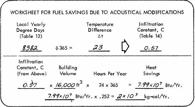
T, is 8382/365 = 23°F. The building volume is 2000 ft2 x 8 ft = 16,000 ft3. For a T of 23°F, the infiltration constant is approximately .57 (from Table 14) so q. = .57 x 16,000 = 9120 Btu/hr. The annual energy savings is therefore 9120 x 24 x 365 = 7.99 x 10⁷ Btu/yr. (2 x 10⁷ kg-cal/yr).(Note that the degree-day concept is based on Fahrenheit degrees. To calculate the energy savings in metric units convert the answer in Btu/year to kilogram-calories/year by multiplying by 0.252.)
These calculations should be carried out on Worksheet No. 3, a portion of which is reproduced as follows: (A complete worksheet is included at the end of the manual.)
Noise Reduction modifications beyond the sealing of infiltration cracks usually involve modifications to windows or to the walls of the building. These modifications usually affect the conductive heat loss by decreasing the thermal transmittance, thereby providing an energy savings.
The relationship presented above for conductive heat loss is for the loss through a single element of area A. If more than a single element is modified, the relationship must be applied to each element separately and the decreases in heat flow through each element then added to determine the total heat savings.
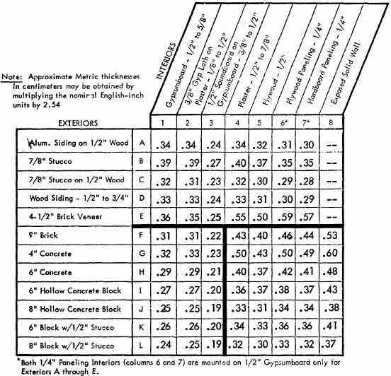
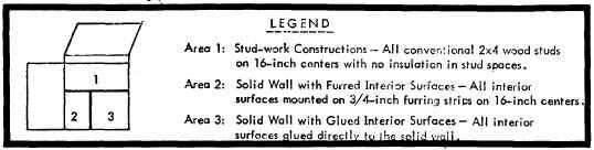
Thermal transmittance values (U - Factors) for commonly used basic constructions are given in Table'15. The U - Factors for the stud-work constructions of Area 1 that range from .59 to .23 will be decreased if fibrous absorption is added to the stud-space. The effect of added absorption on the wall's U - Factor may be determined from Table 16. To obtain a U - Factor for walls with stud-space absorption, first find the basic U - Factor in Table 15, then read the adjusted U - Factor in the appropriate column of Table 16.
| U- Factor With No Absorption* | New U - Factor with Absorption* | |
|---|---|---|
| 2" to 2. 5" (5.08 to 6. 35 cm) | 3" to 4" (7.62 to 10.16 cm) | |
| .60 | .12 | .09 |
| .50 | .12 | .09 |
| .40 | .11 | .09 |
| .30 | .10 | .08 |
| .20 | .09 | .07 |
Thermal transmittance values (U - Factors) for commonly used windows are given in Table 17 and values for commonly used doors are given in Table 18.
| Window | U - Factor* |
|---|---|
| Single Pane Glass | 1.13 |
| Double Pane (½" or 1.3 cm air space) | .58 |
| Storm Windows | .56 |
| Door Thickness | U - Factor* | ||
|---|---|---|---|
| No Storm Door | With Storm Doors | ||
| Wood with Window | Metal with Window | ||
| 1" (2.54cm) | 0.64 | 0.30 | 0.39 |
| 1.25" (3.18cm) | .55 | 0.28 | 0.34 |
| 1.5" (3.81 cm) | .49 | 0.27 | 0.33 |
| 2" (5.08cm) | .43 | 0.24 | 0.29 |
The heat flow through an area A may be determined from the relation qc = UAT. Note that for the same area, A and some temperature difference T, the change in heat flow due to a modified wall element may be determined from the relation: q = (U2 - U1) AT where U1 and U2 are the U - Factors before and after the modification.
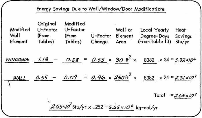
On the Minneapolis house of Example 7, it has been determined that the wall facing a planned highway will require the following modifications:
The wall construction is 4.5" (11.43 cm) brick veneer with a ¾" (1.9 cm) plaster interior finish. The wall is 35' (10.7 m) long and 8' (2.4 m) high. Determine the annual heat energy that will be saved due to the acoustical modifications.
The U - Factor for the wall with no absorption is .55 (from Table 15). The effect of the added absorption will be to decrease the wall's U - Factor to .09 (from Table 16). The change in U - Factor, (U2 - U1), for the wall is .55 - .09= .46.
The U - Factor for the original single pane window is 1.13 (from Table 17). The U - Factor of the new double pane windows will be .58. The change in U - Factor (U2 - U1), for the windows is 1.13 - .58 = .55.
The total window area is 2 x 3' x 5' = 30 ft2 (2.8 m2). The wall area less the windows is 8' x 35' - 30 = 250 ft2 (23 m2). The yearly degree - days for Minneapolis is found in Table 13 to be 8382. Therefore the temperature difference, T, is 8382/365 = 23°F.
Therefore the change in heat flow through the windows will be .55 x 30 x 23 = 380 Btu/1-ir, and the change in heat flow through the wall will be .46 x 250 x 23 = 2645 Btu/hr.
The total heat flow change due to the modifications will be 380 + 2645 = 3025 Btu/hr. To find the heat loss change for a full year, multiply the heat flow in Btu/hr by 8,760 (24 x 365 = 8,760). The total annual heat energy saved will be 3025 x 8,760 = 2.65 x 10⁷ Btu/yr (6.68x 10⁶ kg -cal/yr).
(Note that this, calculation is based on degree-days for Fahrenheit degrees. To calculate the energy savings in metric units, convert the answer in Btu/yr to kilogram-calories/year by multiplying by 0.252.)
These calculations should be carried out on Worksheet No. 3 a portion of which is reproduced as follows: (A complete worksheet is included at the end of the manual.)
To convert the heat energy savings in Btu (kg-cal) calculated above, to actual dollars, the amount of heating fuel saved must first be determined. Table 19 gives typical characteristics of commonly used heating fuels.
| Fuel Factor | Coal1 | Oil2 | Gas3 |
|---|---|---|---|
| Typical Heating Value | 13,000 Btu/lb | 140,000 Btu/gal | 1,025 Btu/ft3 |
| Typical Furnace Efficiency Factor | 0.6 | 0.7 | 0.8 |
| Heating Value Efficiency Product | 7,800 Btu/lb | 98,000 Btu/gal | 820 Btu/ft3 |
1 Multiply values in Btu/lb by .56 to obtain values in kg-cal/kg.
2 Multiply values in Btu/gal by .067 to obtain values in kg-cal/liter.
3 Multiply values in Btu/ft by 8.9 to obtain values in kg-cal/m3.
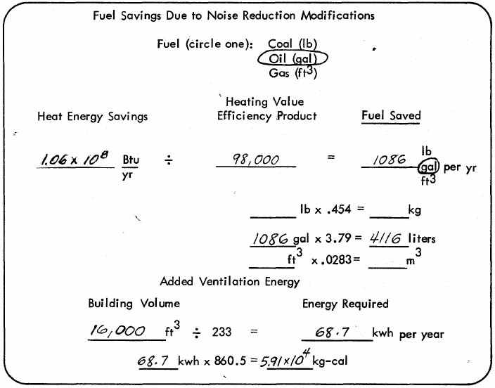
The total annual heat energy savings in Btu/yr (kg-cal/yr) when multiplied by the Heating Value Efficiency Product for the appropriate fuel (as given in Table 19) will result in the total annual fuel saved in pounds/ gallons or Cubic feet (kilograms, liters or cubic meters).
The savings in annual heat energy due to Noise Reduction modifications should be compared with the increased energy consumed by ventilation equipment if mechanical ventilation is made necessary by implementation of Noise Reduction modifications.
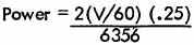
Ventilation equipment energy consumption may be determined from the following relationship:
HP = 2 (cfm) (TP)/6356
where HP is the required ventilation fan horsepower, cfm is the air flow rate and TP is the total pressure head in inches of water.15,16
Assuming that the elimination of infiltration and windows requires minimum extra mechanical ventilation at a rate of one air change per hour, then the air flow rate in ft3/minute may be determined by dividing the volume of the ventilated space (in ft3) by 60. Typical residential duct pressure may be assumed to be .25 inches of water. Hence the ventilation fan power is given by:
The ventilation fan power may be converted to kilowatts (kw) by multiplying by the factor .746. Assuming that ventilation will be required for approximately 6 months out of every year (the rest of the year, the heating system will supply ventilation air), the number of hours in a 6-month period may be multiplied by the fan power in kw to obtain kilowatt-hours. The result is as follows:

Therefore, the required energy in kwh may be determined simply by dividing the volume of the ventilated space, V in ft3, by the factor 233. To determine the required energy in kilogram-calories, multiply the value in kilowatt-hours by 860.5 or simply divide the volume of the ventilated space, V, in m3 by the factor .00766.
These relationships may be summarized as follows:
Ventilation Fan Energy Requirements
Volume of Space in ft3/233 = Required kilowatt-hours
Volume of Space in m3/.00766 = Required kilogram-calories
From Table 19, fuel oil has a Heating Value Efficiency Product of 98,000 Btu/gal (6,566 kg-cal/liter). Therefore the amount of fuel oil that will be saved is:
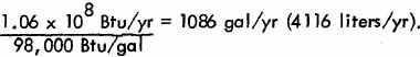
The volume of the building is 16,000 ft3(453.1 m3 ) so the energy required annually for ventilation will be:
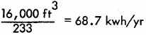
Therefore, 1,086 gallons of fuel oil will be saved every year and an extra 68.7 kwh will be consumed. The procedures of Chapter 5 may be used to determine the actual dollar costs of this energy.
These calculations should be carried out on Worksheet No. 3 a portion of which is reproduced as follows: (A complete worksheet is included at the end of the manual.)