
This section describes the differences between the following two basic types of noise barrier systems, as well as special features associated with each:
Ground-Mounted
and
Structure-Mounted
Ground-mounted noise barrier systems are barriers constructed into or placed on top of the ground. This section will discuss the features of the three basic types of ground-mounted noise barrier systems:
Noise barriers constructed from natural earthen materials such as soil, stone, rock, rubble, etc. in a natural, unsupported condition are termed, noise berms (see Figures 26 and 27). These types of barriers are typically constructed with surplus materials available on the project site or from materials transported from an off-site location. The source and availability of such material are factors which can significantly affect the cost of such systems. Noise berms generally occupy more space than a wall type of barrier. This is mainly due to the sloping sides of the berms which must be gradual enough to maintain stability of the structure. For most berms, side slopes of 2:1 "run:rise" (i.e., 2 m horizontal to 1 m vertical) are typical, although on occasion steeper slopes (1½:1) may be acceptable. For berms constructed from rock (in an unsupported condition) side slopes as steep as 1:1 may be acceptable. The top of the berm may be of minimal width (with normal slope rounding) or it can be designed with a relatively wide plateau. While the level plateau area results in more space required to construct the berm, it provides for easier maintenance of the berm and offers an area for placement of such features as plantings, a right-of-way fence, or even a noise wall which could be used for improving the acoustical effectiveness by effectively increasing the height of the barrier system.
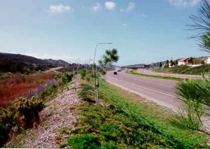
Figure 26. Noise berm
photo #2584
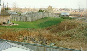
Figure 27. Noise berm
photo #2712
Other factors to consider in selecting a berm as a noise barrier system include:
Most noise wall systems are fabricated off-site, i.e., all of the components for this type of noise wall (foundation components excluded) are fabricated in a plant, then transported to the project site, and assembled on-site. Noise wall systems fabricated on-site include only cast-in-place concrete walls. This section includes a discussion of the following types of noise wall systems.
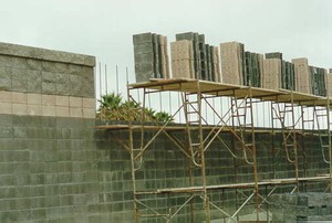
This type of system consists of noise barrier panels mounted between foundation-supported posts (see Figure 28). Primary elements of this type of barrier include: post and post/foundation attachments, panels, and panel to post connections.
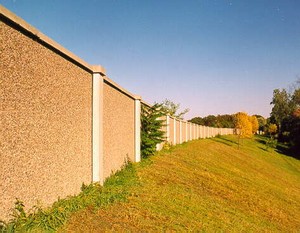
Figure 28. Post and panel noise wall
photo #27
Figure 29. Post and panel attachments: concrete cylinder
photo #528
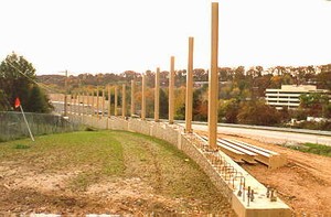
Figure 30. Post and panel attachments: continuous footing
photo #529
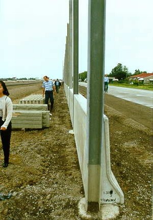
Figure 31. Post and panel attachments: embedded post
photo #5
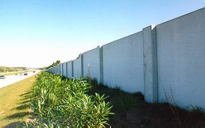
Figure 32. Full height panel
photo #2946
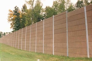
Figure 33. Stacked panel
photo #2680
Figure 34. Post and panel: shipping requirements
photo #527
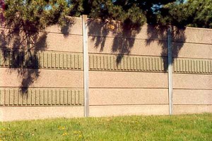
Figure 35. Post and panel: panel aesthetics photo #2979
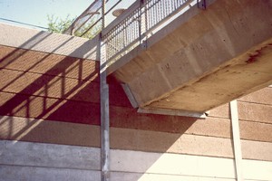
Figure 36. Post and panel: installation implications
photo #6049
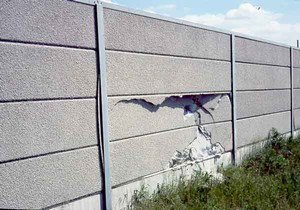
Figure 37. Post and panel: maintenance considerations photo #5572
This type of system is a specialized type of post and panel system (see Figures 38 and 39) used in areas where sound reflections (either single or multiple) could be a problem if the more standard vertical noise walls were used (see Section 3.5.4). This type of system is most commonly manufactured using precast concrete elements, but at least one known system uses wood.
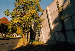
Figure 38. Tilted post and panel noise wall: community side
photo #36
Figure 39. Tilted post and panel noise wall: highway side
photo #34
Aside from the specialized loading treatments related to the tilted design, the considerations for post and panels discussed above apply to tilted post and panel systems. Since the angle of tilt is generally in the range of ten degrees, the issue of the wall being flat enough for people climbing it does not appear to be substantial. Because of aesthetics, care should be taken where such tilted walls transition to vertical walls or end abruptly. Similarly, the proximity of such tilted walls to residences and other areas of public use is probably more significant from a visual standpoint due to the possible perception of the wall "falling down."
This type of system includes barriers constructed of fabricated brick or masonry block units (see Figures 40-43). Typically, these types of systems are constructed by laying the brick or masonry block in a conventional fashion using a continuous spread footing as a base. However, in certain instances, such barriers may be constructed on a base beam supported at the ends by the posts or by the top of the concrete caissons for the posts.
 |
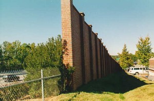 |
| Figure 40. Brick noise wall photo #8014 |
Figure 41. Brick noise wall photo #560 |
 |
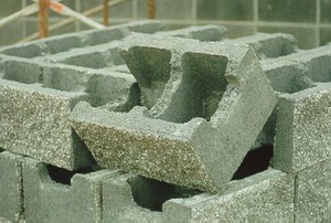 |
| Figure 42. Masonry block noise wall photo #2454 |
Figure 43. Masonry block noise wall photo #2457 |
This type of barrier system includes barriers which support themselves. Such barriers, constructed to date, can be grouped into the following general categories:
These systems generally obtain their stability from the combination of their "zig-zag-like" or "trapezoidal" configuration and their system mass (see Figures 44 and 45). Depending upon soil conditions, precast free-standing walls may be supported by compacted soil and a well-drained stone base, a plain cement concrete leveling pad, or a continuous reinforced concrete footing.
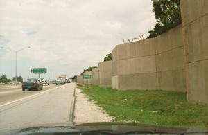
Figure 44. Precast free standing concrete noise wall
photo #1206
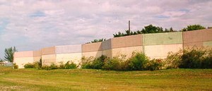
Figure 45. Precast free standing concrete noise wall
photo #1218
These systems obtain their stability from a type of structural shell, typically either concrete, wood, or plastic, which is filled with soil and then planted (see Figures 46 and 47). These systems are most often supported by some form of continuous concrete leveling pad or footing. However, depending on the design and the type of plantings, these systems may be set directly on top of the existing ground with little or no preparation other than minor leveling.
Careful consideration needs to be given to the type of planting selected and to the means for providing adequate watering of the plant material during all seasons. Maintenance requirements can be significant on such systems, particularly related to items such as weeding, removing large saplings which grow from blown-in weed seeds (if not removed they can adversely affect the structural integrity of the barrier), and replacing pockets of washed out soil. Safety, security and liability issues such as the ability to climb the steps of the planted wall should also be considered.
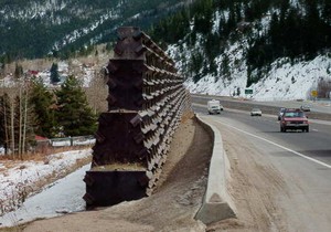
Figure 46. Bin type noise wall: plastic
photo #247
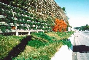
Figure 47. "Planted" noise wall: concrete
photo #2567
This special type of barrier system (also referred to as a gabion system) is comprised of crushed rock contained in large rectangular baskets made of heavy wire mesh (see Figure 48). For aesthetic purposes, these wires can be coated with vinyl which are available in various colors. The baskets are stacked on top of each other in a pyramid fashion to obtain the required barrier height and stability. The baskets are typically placed on well draining, compacted ground. Their structure is flexible enough to tolerate some settlement. This type of system is only feasible if sufficient quantities of suitable rock material are readily available close to or on the project. Little, if any, plant life can be expected to grow on or within this barrier system. The system adapts well to rolling topography.
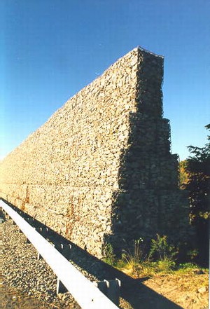
Figure 48. Stone crib noise wall
photo #549
The direct burial panel type is a special panel system which involves burying a portion of one end of the panel (either precast concrete or wood) directly into the ground with no other means of foundation support (see Figure 46). With this type of system, the panels are usually full height and the connection to adjacent panels are typically designed as a tongue and groove system. Since differential settlement of the panels will most likely occur, a smooth top-of-wall profile cannot be expected. Therefore, a jagged profile should be considered during the design of this system (see Figure 47). In some cases, this differential settlement may not be even throughout the length of each panel, thus causing tilting of the panels and ultimately resulting in separating and gapping at the vertical tongue and groove joints.
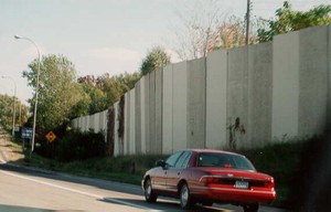
Figure 49. Direct burieal panels
photo #348
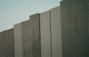
Figure 50. Direct burieal panels
photo #351
In certain instances it may be necessary and advantageous to utilize the bottom portion of a noise wall system to retain earth from either the residential or roadway side. Such applications have been successfully employed where barriers are constructed near the slope hinge point of a highway on fill and near the top of a highway cut section (see Figure 51).
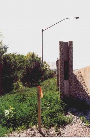
Figure 51. Noise walls used to partially retain earth
photo #8027
In such applications which have employed a post and panel system, the normal depth of the foundation for the noise barrier wall is usually sufficient to retain fills up to 500 mm (1.5 feet). Otherwise, careful structural analysis of the system is required to assure that the bottom portion of the panel (if full height) or the bottom panels in a stacked panel system are sufficiently strong to retain the soil (see Figure 52). Panel to post connections and the joints between stacked panels require similar analysis. In these systems, special drainage designs may be needed to assure that water does not "pond" or saturate the soil retained by the noise wall. In addition, the design should allow for proper drainage of the soil via weeping holes in the walls or via other suitable means.
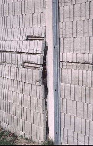
Figure 52. Noise walls used to partially retain earth
photo #480
Other types of noise walls (concrete block, free standing, cast in place, stone crib, etc.) may be considered for such earth retaining applications, but only after the same careful consideration of the above factors. Combination retaining wall/noise barrier systems (generally requiring more significant depths of soil) are discussed in Section 4.2.2.1.
Potential also exists for the adjacent land owner to re-grade their property in the vicinity of the noise barrier. If the surrounding topography has the potential for regrading by adjacent owners, then it should be assumed that this will occur and the impact of this action must be considered in the design of the noise barrier.
These type of barriers are constructed at the project site (see Figure 53). The construction process includes excavating for the footing, erecting form work, setting reinforcement steel, pouring concrete, surface finishing, and curing. Except for certain foundation elements, such systems are significantly different from the noise wall systems discussed in the previous sections in terms of construction techniques, architectural and aesthetic treatment processes, and inspection and quality control procedures. All material testing and inspection procedures must be done in the field both during construction and on an as-erected product. All casting and curing occurs under a variety of weather conditions as compared to more controlled conditions for many of the components of prefabricated barrier systems.
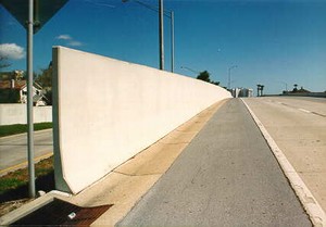
Figure 53. Cast-in-place concrete noise wall
photo #1054
Form liners and architectural inserts must be placed on vertical or near vertical surfaces of the form work which may lead to a significant increase in imperfections in the wall surface when compared to precast components usually cast in a horizontal position. In addition, the application of concrete retarding chemicals to the vertical form work surfaces for the purposes of obtaining an exposed aggregate finish is significantly more difficult than in precast operations. Therefore, obtaining a consistent and acceptable exposed aggregate surface may not be possible. Surface textures obtained through raking, brushing, or stamping of concrete are not possible with cast-in-place walls.
Many noise barrier systems consist of a portion of the barrier height obtained through use of an earth berm with the remainder of the required height achieved by placing a noise wall on top of the berm (see Figures 54 and 55). The foundation, post, and panel considerations for these wall portions are similar to those discussed above.
Figure 54. Combination noise berm and noise wall system
photo #27
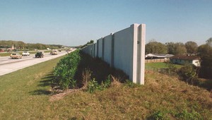
Figure 55. Combination noise berm and noise wall system
photo #993
Additional considerations with this combination type of system relate to the following factors:
This section discusses the types of noise walls used on structures, the concerns related to structure-mounted noise walls, and the general design and construction techniques used to address these concerns. There are two primary types of structure-mounted noise walls:
Figure 56. Noise wall on a bridge
photo #2374
A number of techniques have been successfully employed to attach noise walls to bridges (see Figures 56 to 59). While somewhat different procedures and operations exist for attaching noise walls to existing bridges as compared to attachments to new bridges, the resultant attachment types are similar enough to be discussed under the following general categories:
Figure 57. Noise wall on a bridge
photo #5231
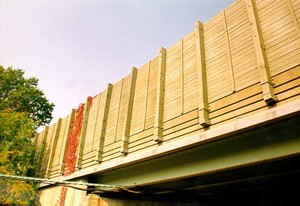
Figure 58. Noise wall on a bridge
photo #1717
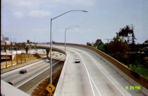
Figure 59. Noise wall on a bridge
photo #5090
Placing a new noise wall on an existing bridge adds a significant amount of stress on a structure caused be the additional weight and rotational loading for which the existing structure may not have been originally designed. This may result in the need to add additional girders, beams, and diaphragms; strengthen the existing bridge deck; or modify the existing parapet. Additional solutions which should be considered are reducing the weight of the noise wall by using light weight material or, only if absolutely necessary, by reducing the height of the wall or, ultimately, eliminating the construction of the wall. The latter should only be considered under absolutely severe situations.
Besides the obvious additional costs of such structural modifications (above the noise wall cost), other issues related to modifying an existing bridge include:
While additional costs are still incurred (compared to the same bridge without a noise barrier), the ability to design the noise wall as an integral part of the overall structure addresses most if not all of the loading and traffic-related concerns discussed above.
The proximity of the noise wall to the traveled portion of the bridge usually makes the wall considerably more susceptible to damage (compared to most ground-mounted noise walls). Such damage (see Figures 60 and 61) may be caused by vehicle impact, airborne debris such as stones, vehicle parts, snow removal operations, or material from salt spreaders in areas subject to snow fall.
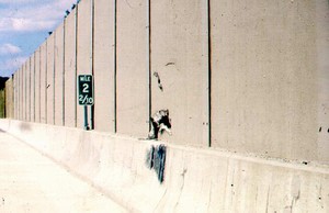
Figure 60. Noise wall damage from vehicular impact
photo #5331
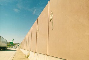
Figure 61. Noise wall damage from airborne debris
photo #1281
Factors considered in addressing this concern include:
While these factors are typically considered by the noise wall designers, the degree of consideration can vary significantly during the decision-making process. The use of barrier materials which tear (such as metal) rather than break/shatter into pieces should be considered this process.
The proximity of bridge-mounted noise walls to traffic has raised concerns related to issues such as vehicular sight distance, barrier shading which increases potential for highway icing, and adverse effects on highway lighting. These issues are discussed elsewhere in this document (see Sections 9.2 and Sections 9.8).
Snow drifting and storage implications, restrictions to bridge inspection teams using bucket trucks to inspect beams, and maintenance of the noise wall itself including graffiti removal, noise barrier and structure damage repair, repainting, etc., are some of the concerns which should be considered during all stages of design and construction. These concerns, except for bridge inspection, are common to both ground-mounted and structure-mounted systems. These concerns are generally greater for bridge-mounted noise walls due to their proximity to the roadway and accessibility limitations.
Retaining walls are typically constructed to retain a highway fill section (where the adjacent ground is lower than the highway grade) or to retain the adjacent ground (where the highway is in cut in relation to the adjacent ground). In either case, the possibility exists that the installation of a noise barrier wall may be warranted either as a part of the retaining wall or in the immediate vicinity of the structure.
Although the required height of a noise barrier system could be accomplished by placing an earth berm behind the retaining wall, such a condition is relatively rare and would be evaluated in the context of loads on the retaining wall. Therefore, the discussion in this section focuses on the variety of techniques used to construct a noise barrier wall on or near a retaining wall (see Figures 62 and 63).
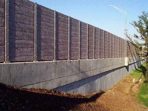
Figure 62. Noise wall on a retaining wall
photo #2947
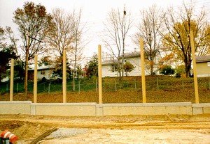
Figure 63. Noise wall on a retaining wall
photo #531
Where the retaining wall is cast-in-place (see Figures 64 to 66), the necessary noise barrier height may be attained in the following manners:
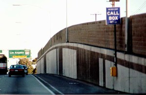
Figure 64. Combination cast-in-place retaining wall and noise wall
photo #1844
Whether the retaining wall is new or existing, the structure must be capable of accommodating the additional dead loads and torsion loads of the noise wall. In addition to structural considerations, other concerns with this type of a retaining wall/noise barrier system are discussed in the following sections as they relate to specific types of installations.
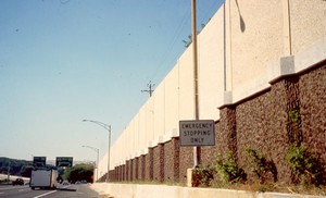
Figure 65. Combination cast-in-place retaining wall and noise wall
photo #5004
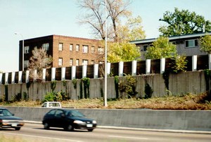
Figure 66. Combination cast-in-place retaining wall and noise wall
photo #329
Placement of a noise barrier wall behind a cast-in-place retaining wall (see Figures 67 and 68) requires careful consideration of the load transfers (both dead load and torsion loads) on both the earth behind the retaining wall and the retaining wall itself.
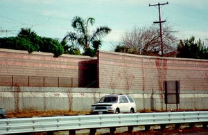
Figure 67. Noise wall behind cast-in-place retaining wall
photo #1745
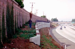
Figure 68. Noise wall behind cast-in-place retaining wall
photo #1691
As compared to a noise wall mounted directly on top of a retaining wall, additional considerations related to the area between the noise wall and the face of the retaining wall with this type of a system include:
These issues are discussed in more detail in Section 6.2, Section 7.1, and Section 9.4, respectively.
Many instances exist where highway fills or cut slopes are retained by proprietary systems which use metal straps, grids, or other techniques to strengthen, reinforce, and/or retain the earth mass behind the wall system. In this type of retaining wall system, the "retained" earth mass is the retaining wall system's supporting medium, as opposed to the structure itself. While these systems typically incorporate a concrete facing of one form or another, this facing is not the primary structural element of the retaining wall system, and thus, cannot be relied upon to support the loads of a noise barrier. Without an independent footing (usually a spread footing which may be tied to the cap of the retaining wall) a noise wall cannot be placed on top of, attached to the side of, or installed directly behind the face of this type of retaining wall system.
The following is a discussion on two typical methods of overcoming these restrictions. These methods should not be considered all inclusive and are not intended to restrict innovative approaches.
With either of these two techniques, the same issues related to maintenance, landscaping, drainage, safety, and access referred to in Sections 6.2, Sections 7.1, and Sections 9.4 should be considered.
A variety of retaining wall systems exist which are comprised of pre-manufactured materials such as precast concrete, metal, and plastic components which are assembled on site (see Figure 69). Some of these systems may also incorporate earth within their structural facing. In general, noise barrier walls cannot be supported directly on top of the face of these systems. Thus, their construction must consider the same factors as discussed above for barriers located behind retained earth systems.
Figure 69. Noise wall caisson foundations behind pre-manufactured retaining wall
photo #6534
Situations and conditions often warrant the incorporation of special features into the construction of noise walls. These features may be required because of engineering, acoustical, and/or aesthetic reasons.
For the purpose of this discussion, caps are considered to be separate elements of the barrier system applied to either the top of noise walls or to the top of the noise wall posts. The "cap look," which is accomplished as an integral part of the fabrication/construction of the noise barrier wall panels, is discussed further in Section 6.1.3.
Special modifications of noise wall systems are often required in areas where the access from one side of the wall to the other is required (or anticipated to be required) on either a regular basis (as per maintenance personnel and/or equipment), or on an irregular basis (as per emergency personnel and equipment). The locations and frequency of such access openings is, usually determined by the responsible organization (DOT, emergency response unit, fire departments, police departments, etc.) on a case-by-case basis. Emergency and pedestrian access openings and doors are usually required to be identified on both sides of the barrier by signs denoting mile marker, station, or some other distinctive identifying feature. Section 9.4 discusses in detail several techniques used to provide such access openings in noise barrier walls.
Normally, water falling in the vicinity of a noise wall is carried longitudinally along the barrier in a drainage swale to a catch basin or inlet from which it is piped either under the wall or into the main roadway drainage system. In certain instances, it is necessary to allow water collected in front of or behind a noise wall to pass to the other side of the barrier. Design of such openings in the noise wall must assure that their size and frequency are such as to not degrade the acoustical effectiveness of the noise wall system. A more detailed discussion is provided in Section 7.1.
A noise wall may, in certain situations, be the only possible location or the most feasible location for mounting or attaching other roadway-related elements. Examples of such elements include call boxes, highway speed limit or advisory signs, highway lighting fixtures, etc. Incorporation of such features should occur integrally with the design of the noise wall, not as an add-on element. Safety considerations related to clearances (both horizontal and vertical), electrical connections, sight distances, etc. are essential. This subject is discussed in more detail in Section 7.2.
|
Noise Wall Types. |
||||
|---|---|---|---|---|
| Item# | Main Topic | Sub-Topic | Consideration | See Also Section |
| 4-1 | Noise Berm | Aesthetic | Consider the visual implications on both residential and highway side and the landscaping required. | 4.1.1 |
| Consider the destruction of existing features for construction of the berm. | 4.1.1 | |||
| Drainage and Utility | Provide for adequate drainage requirements. | 4.1.1 | ||
| Safety | Consider right-of-way requirements. | 4.1.1 | ||
| Maintenance | Consider accessibility to and around berm and landscaping requirements. | 4.1.1 | ||
| 4-2 | Post and Panel Noise Wall | Acoustical | Ensure that there are no sound transmission leaks between stacked panels and panel-to-post connections. | 4.1.2,1 |
| Aesthetic | Coordinate texture treatments with stacked panels so that the joints are either concealed by the pattern or become a part of the pattern. | 4.1.2.1 | ||
| Consider special concerns related to tilted post and panel designs. | 4.1.2.1.1 | |||
| Drainage and Utility | Overhead wires and other utilities may preclude the ability to use full height precast panels. | 4.1.2.1 | ||
| Structural | Provide for the impact of panel-to-post wind and dead load transfers. | 4.1.2.1 | ||
| Provide specialized loading treatments related to tilted post and panel designs. | 4.1.2.1.1 | |||
| 4-3 | Free Standing Noise Wall: Precast Concrete |
Maintenance | Consider landscaping access requirements. | 4.1.2.3.1 |
| Installation | For precast : consider size limitations, shipping requirements, traffic implications, reusability of precast panels, quality assurance process. | 4.1.2.3.1 5.1 |
||
| For cast-in-place: consider on-site material testing and inspection procedures during construction and on an as-erected product and weather concerns for on-site casting and curing. | 4.1.2.6 5.1 |
|||
| 4-4 | Free Standing Noise Wall: Planted or Bin-Type |
Aesthetic | Consider the type of plantings. | 4.1.2.3.2 |
| Maintenance | Ensure landscaping upkeep. | 4.1.2.3.2 | ||
| Consider litter implications. | 12.7 | |||
| Safety | Consider implementing a deterrent for climbing on barrier girts. | 4.1.2.3.2 | ||
| 4-5 | Free Standing Noise Wall: - Stone Crib |
Safety | Consider implementing a deterrent for climbing on barrier girts. | 4.1.2.3.3 |
| 4-6 | Direct Burial Panels | Acoustical | Consider possible separating and gapping at the vertical tongue and groove joints. | 4.1.2.4 |
| Aesthetic | Consider a jagged top-of-wall profile rather than a smooth profile. | 4.1.2.4 | ||
| Structural | Consider possible differential settlement of panels. | 4.1.2.4 | ||
| 4-7 | Noise Walls Used to Partially Retain Earth | Structural | Consider loading concerns on the retained soil. | 4.1.2.5 |
| Consider the impact if adjacent land owners re-grade their property in the vicinity of the noise wall. | 4.1.2.5 | |||
| Drainage and Utility | Ensure proper drainage so that water does not "pond" or saturate the soil retained by the noise wall. | 4.1.2.5 | ||
| 4-8 | Cast-in-Place | Aesthetic | Form liners and architectural inserts must be placed on vertical surfaces of the form work which may increase imperfections in the wall surface. | 4.1.2.6 |
| Application of concrete retarding chemicals to the vertical form work surfaces for the purposes of obtaining an exposed aggregate finish is difficult. | 4.1.2.6 | |||
| Installation | Consider on-site material testing and inspection during construction and on an as-erected product. | 4.1.2.6 | ||
| Consider weather concerns for on-site casting and curing. | 4.1.2.6 | |||
| 4-9 | Combination Noise Wall and Noise Berm | Structural | Consider reactive loadings on the berm's soil due to the wall portion. | 4.1.3 |
| Consider a plateau area on top of the berm. | 4.1.3 | |||
| Safety | Consider the need for and location of right-of-way fence. | 4.1.3 | ||
| 4-10 | Noise Walls on Bridges | Structural | Consider weight stress and rotational loading. | 4.2.1 |
| Consider bridge vibrations due to existing traffic. | 4.2.1 | |||
| Consider bridge vibrations from construction operations. | 4.2.1 | |||
| Consider the impact of any parapet attachments. | 4.2.1 | |||
| Consider the type of anchoring system. | 4.2.1 | |||
| Consider top of barrier profile if the top of parapet profile is not smooth and/or consistent. | 4.2.1 | |||
| Safety | Ensure protection of traffic (both on and beneath bridge). | 4.2.1.4 | ||
| Consider the potential for damage and injury in the event of the noise wall or parts thereof falling from the structure. | 4.2.1.5 | |||
| Ensure adequate vehicular sight distance. | 4.2.1.6 | |||
| Consider barrier shading resulting in highway icing, and adverse effects on highway lighting. | 4.2.1.6 | |||
| Maintenance | Consider accessibility. | 4.2.1.7 | ||
| Consider snow drifting and storage implications. | 4.2.1.7 | |||
| Consider possible restrictions to bridge inspection teams. | 4.2.1.7 | |||
| 4-11 | Noise Walls on Retaining Walls | Structural | Consider any additional dead and torsion loads due to the noise wall. | 4.2.2 |
| Drainage and Utility | Provide for adequate drainage requirements. | 4.2.2 |

