

Comprehensive Design Example for Prestressed Concrete (PSC) Girder Superstructure Bridge
Design Step 5 Design of Superstructure
Design Step 5.4 Loss of Prestress (S5.9.5)
Design Step 5.4.1 General
Loss of prestress can be characterized as that due to instantaneous loss and time-dependent loss. Losses due to anchorage set, friction and elastic shortening are instantaneous. Losses due to creep, shrinkage and relaxation are time-dependent.
For pretensioned members, prestress loss is due to elastic shortening, shrinkage, creep of concrete and relaxation of steel. For members constructed and prestressed in a single stage, relative to the stress immediately before transfer, the loss may be taken as:
ΔfpT = ΔfpES + ΔfpSR + ΔfpCR + ΔfpR2 (S5.9.5.1-1)
where:
| ΔfpES | = loss due to elastic shortening (ksi) |
| ΔfpSR | = loss due to shrinkage (ksi) |
| ΔfpCR | = loss due to creep of concrete (ksi) |
| ΔfpR2 | = loss due to relaxation of steel after transfer (ksi) |
Notice that an additional loss occurs during the time between jacking of the strands and transfer. This component is the loss due to the relaxation of steel at transfer, ΔfpR1.
The stress limit for prestressing strands of pretensioned members given in S5.9.3 is for the stress immediately prior to transfer. To determine the jacking stress, the loss due to relaxation at transfer, ΔfpR1, needs to be added to the stress limits in S5.9.3. Practices differ from state to state as what strand stress is to be shown on the contract drawings. The Specifications assume that the designer will determine the stress in the strands immediately before transfer. The fabricator is responsible for determining the jacking force by adding the relaxation loss at transfer, jacking losses and seating losses to the Engineer-determined stress immediately prior to transfer. The magnitude of the jacking and seating losses depends on the jacking equipment and anchorage hardware used in the precasting yard. It is recommended that the Engineer conduct preliminary calculations to determine the anticipated jacking stress.
Accurate estimation of the total prestress loss requires recognition that the time-dependent losses resulting from creep and relaxation are interdependent. If required, rigorous calculation of the prestress losses should be made in accordance with a method supported by research data. However, for conventional construction, such a refinement is seldom warranted or even possible at the design stage, since many of the factors are either unknown or beyond the designer's control. Thus, three methods of estimating time-dependent losses are provided in the LRFD Specifications: (1) the approximate lump sum estimate, (2) a refined estimate, and (3) the background necessary to perform a rigorous time-step analysis.
The Lump Sum Method for calculating the time-dependent losses is presented in S5.9.5.3. The values obtained from this method include the loss due to relaxation at transfer, ΔfpR1. To determine the time-dependent loss after transfer for pretensioned members, ΔfpR1 needs to be estimated and deducted from the total time-dependent losses calculated using S5.9.5.3. The refined method of calculating time-dependent losses is presented in S5.9.5.4. The method described above is used in this example.
A procedure for estimating the losses for partially prestressed members, which is analogous to that for fully prestressed members, is outlined in SC5.9.5.1.
Design Step 5.4.2 - Calculate the initial stress in the tendons immediately prior to transfer (S5.9.3).
| fpt + ΔfpES | = 0.75fpu = 0.75(270) = 202.5 ksi |
Design Step 5.4.3 - Determine the instantaneous losses (S5.9.5.2)
Friction (S5.9.5.2.2)
The only friction loss possible in a pretensioned member is at hold-down devices for draping or harping tendons. The LRFD Specifications specify the consideration of these losses.
For this example, all strands are straight strands and hold-down devices are not used.
Elastic Shortening, ΔfpES (S5.9.5.2.3)
The prestress loss due to elastic shortening in pretensioned members is taken as the concrete stress at the centroid of the prestressing steel at transfer, fcgp, multiplied by the ratio of the modulus of elasticities of the prestressing steel and the concrete at transfer. This is presented in Eq. S5.9.5.2.3a-1.
ΔfpES = (Ep/Eci)fcgp (S5.9.5.2.3a-1)
where:
| fcgp | = sum of concrete stresses at the center of gravity of prestressing tendons due to the prestressing force at transfer and the self-weight of the member at the sections of maximum moment (ksi) |
| Ep | = modulus of elasticity of the prestressing steel (ksi) |
| Eci | = modulus of elasticity of the concrete at transfer (ksi) |
Applying this equation requires estimating the stress in the strands after transfer. Proposed estimates for pretensioned members are given in S5.9.5.2.3a.
Alternatively, the loss due to elastic shortening may be calculated using Eq. C5.9.5.2.3a-1:
 |
(SC5.9.5.2.3a-1) |
where:
| e54.5' | = average eccentricity of prestressing steel at midspan (in.) |
| fpbt | = stress in prestressing steel immediately prior to transfer as specified in Table S5.9.3-1; 0.75fpu (ksi) |
| Mg | = midspan moment due to memberself-weight (k-in) |
The alternative approach is used for this example.
ΔfpES = 13.7 ksi
Design Step 5.4.4 - Calculate the prestressing stress at transfer
| fpt | = Stress immediately prior to transfer - ΔfpES = 202.5 - 13.7 = 188.8 ksi |
Design Step 5.4.5 - Calculate the prestressing force at transfer
| Pt | = Nstrands(Aps)(fpt) = 44(0.153)(188.8) = 1,271 kips (initial loss = 6.77%) |
Design Step 5.4.6 - Time-dependent losses after transfer, refined method (S5.9.5.4)
Refined estimated time-dependent losses are specified in S5.9.5.4. The refined method can provide a better estimate of total losses than the Lump Sum Method of S5.9.5.3.
Design Step 5.4.6.1 - Shrinkage Losses (S5.9.5.4.2)
The expression for prestress loss due to shrinkage is a function of the average annual ambient relative humidity, H, and is given as Equation S5.9.5.4.2-1 for pretensioned members.
ΔfpSR = (17.0 - 0.15H) (ksi) (S5.9.5.4.2-1)
where:
H = the average annual ambient relative humidity (%)
The average annual ambient relative humidity may be obtained from local weather statistics or taken from the map of Figure S5.4.2.3.3-1 shown below.
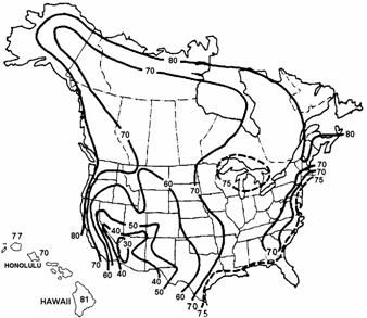
Figure S5.4.2.3.3-1 - Annual Average Ambient Relative Humidity in Percent
Calculate the loss due to shrinkage, ΔfpSR
For the Atlanta, Georgia area, where the example bridge is assumed, the average relative humidity may be taken as 70%.
| ΔfpSR | = 17.0 - 0.15(70) = 6.5 ksi |
Design Step 5.4.6.2 - Creep losses (S5.9.5.4.3)
The expression for prestress losses due to creep is a function of the concrete stress at the centroid of the prestressing steel at transfer, fcgp, and the change in concrete stress at the centroid of the prestressing steel due to all permanent loads except those at transfer, Δfcdp, and is given by the Eq. S5.9.5.4.3-1.
ΔfpCR = 12.0fcgp - 7.0Δfcdp ≥ 0 (S5.9.5.4.3-1)
where:
| fcgp | = concrete stress at the center of gravity of the prestressing steel at transfer (ksi) |
| Δfcdp | = change in concrete stress at center of gravity of prestressing steel due to permanent loads, except the load acting at the time the prestressing force is applied. Values of Δfcdp should be calculated at the same section or at sections for which fcgp is calculated (ksi) |
The value of Δfcdp includes the effect of the weight of the diaphragm, slab and haunch, parapets, future wearing surface, utilities and any other permanent loads, other than the loads existing at transfer at the section under consideration, applied to the bridge.
Calculate the loss due to creep, ΔfpCR
Determine the concrete stress at the center of gravity of prestressing steel at transfer, fcgp.
fcgp = [1.256(2.457) - 0.862]/1.103
= 2.016 ksi
Notice that the second term in both the numerator and denominator in the above equation for fcgp makes this calculation based on the transformed section properties. Calculating fcgp using the gross concrete section properties of the concrete section is also acceptable, but will result in a higher concrete stress and, consequently, higher calculated losses. Deleting the second term from both the numerator and denominator of the above equation gives the stress based on the gross concrete section properties.
The value of fcgp may also be determined using two other methods:
Use the same equation above and set the stress in the strands equal to the stress after transfer (188.8 ksi) instead of the stress immediately prior to transfer (0.75fpu = 202.5 ksi) and let the value of the denominator be 1.0.
Since the change in the concrete strain during transfer (strain immediately prior to transfer minus strain immediately after transfer) is equal to the change in strain in the prestressing strands during transfer, the change in concrete stress is equal to the change in prestressing stress during transfer divided by the modular ratio between prestressing steel and concrete at transfer. Noticing that the concrete stress immediately prior to transfer is 0.0 and that the change in prestressing stress during transfer is the loss due to elastic shortening = 13.7 ksi, fcgp can be calculated as:
fcgp = 13.7/(28,500/4,200)
= 2.019 ksi ≈ 2.016 ksi calculated above (difference due to rounding)
Determine Δfcdp as defined above.
Δfcdp = [(Mdia + Mslab)e54.5']/Ig + [(Mparapet + MFWS)(N.A.beambot - CGSps)]/Ic
Δfcdp = [(138 + 1,696)(12)31.38]/733,320 + [(165 + 222)(12)(51.54 - 5.0)]/1,384,254
Δfcdp = 1.10 ksi
Solving,
| ΔfpCR | = 12.0(2.016) - 7.0(1.10) = 16.49 ksi |
Design Step 5.4.6.3 - Relaxation (S5.9.5.4.4)
The total relaxation at any time after transfer is composed of two components: relaxation at transfer and relaxation after transfer.
After Transfer (S5.9.5.4.4c):
Article S5.9.5.4.4c provides equations to estimate relaxation after transfer for pretensioned members with stress-relieved or low relaxation strands.
For pretensioning with stress-relieved strands:
ΔfpR2 = 20.0 - 0.4ΔfpES - 0.2(ΔfpSR + ΔfpCR) (ksi) (S5.9.5.4.4c-1)
where:
| ΔfpES | = loss due to elastic shortening (ksi) |
| ΔfpSR | = loss due to shrinkage (ksi) |
| ΔfpCR | = loss due to creep of concrete (ksi) |
For prestressing steels with low relaxation properties conforming to AASHTO M 203 (ASTM A 416 or E 328) use 30% of ΔfpR2 given by the above equation.
Relaxation losses increase with increasing temperatures. The expressions given for relaxation are appropriate for normal temperature ranges only.
Losses due to relaxation should be based on approved test data. If test data is not available, the loss may be assumed to be 3.0 ksi.
Calculate the loss due to relaxation after transfer, ΔfpR2
| ΔfpR2 | = 20.0 - 0.4(13.7) - 0.2(6.5 + 16.49) = 9.92 ksi |
For low relaxation strands, multiply ΔfpR2 by 30%.
| ΔfpR2 | = 0.3(9.92) = 2.98 ksi |
Design Step 5.4.7 - Calculate total loss after transfer
| ΔfpT | = ΔfpES + ΔfpSR + ΔfpCR + ΔfpR2 = 13.7 + 6.5 + 16.49 + 2.98 = 39.67 ksi |
Design Step 5.4.8 - Calculate the final effective prestress responses
| Max fpe | = 0.80fpy (Table S5.9.3-1 - Stress Limits for Presstressing Tendons at the Service Limit State after all losses) = 0.8(243) = 194.4 ksi |
Calculate the actual effective prestress stress after all losses
| fpe | = 0.75fpu - ΔfpT = 0.75(270) - 39.67 = 162.83 ksi < 194.4 ksi OK |
Calculate the actual effective prestress force after all losses
| Pe | = Nstrands(Aps)(fpe) = 44(0.153)(162.83) = 1,096 kips (total loss = 19.59%) |
Design Step 5.4.9 - Calculate jacking stress, fpj
As indicated earlier, the Fabricator is responsible for calculation of the jacking force. The calculations presented below are for reference purposes.
As shown earlier, the stress in the prestressing strands immediately prior to transfer is 202.5 ksi.
The Jacking Stress, fpj = Stress immediately prior to transfer + Relaxation loss at transfer
Relaxation at transfer (S5.9.5.4.4b) - time-dependent loss
Generally, the initial relaxation loss is now determined by the Fabricator. Where the Engineer is required to make an independent estimate of the initial relaxation loss, or chooses to do so as provided in S5.9.5.1, the provisions of this article may be used as a guide. If project-specific information is not available, the value of fpj may be taken as 0.80fpu for the purpose of this calculation. For this example, fpj will be taken as 0.75fpu.
Article S5.9.5.4.4b provides equations to estimate relaxation at transfer for pretensioned members, initially stressed in excess of 50% of the tendon's tensile strength, fpu.
For low-relaxation strands:
| (S5.9.5.4.4b-2) |
where:
| t | = time estimated in days from stressing to transfer (days) assumed to be 1 day for this example | |
| fpj | = initial stress in the tendon at the end of stressing (ksi) assumed to be 205.0 ksi for this example | |
| fpy | = specified yield strength of prestressing steel (ksi) | |
| ΔfpR1 | = 2.08 ksi | |
Therefore,
| Jacking stress, fpj | = 202.5 + 2.08 = 204.58 ksi |