U.S. Department of Transportation
Federal Highway Administration
1200 New Jersey Avenue, SE
Washington, DC 20590
202-366-4000
Federal Highway Administration Research and Technology
Coordinating, Developing, and Delivering Highway Transportation Innovations
| REPORT |
| This report is an archived publication and may contain dated technical, contact, and link information |
|
| Publication Number: FHWA-HRT-07-040 Date: October 2011 |
Publication Number: FHWA-HRT-07-040 Date: October 2011 |
Philosophically, the new AASHTO calibration procedure is similar to the old SHRP procedure; however, the manner in which the new procedure is carried out is different. The basic steps of the procedure are as follows:
Few changes were made in the load system calibration procedure, which is carried out in a similar manner to the old SHRP protocol. However, more flexibility is allowed in the number of load levels used.
The deflection sensors are calibrated simultaneously by placing them in a rigid columnar stand along with a reference accelerometer. This expedites the procedure, as the old SHRP protocol specified performing reference calibration one sensor at a time. Data from the accelerometer are double integrated to yield a precise peak reference deflection.
Relative calibration is performed in the same stand as reference calibration, and the procedure checks the quality of the calibration. Sensors are rotated in the stand to remove any bias due to position. Only one rotation is required, which also helps expedite the procedure.
The new protocol requires two operators: the FWD system operator and the calibration system operator. The protocol takes less than 3 h to perform, provided the FWD is in working condition. The detailed FWD calibration protocol is given in appendix A.
The AASHTO protocol is conducted using a new software program, WinFWDCal.(11) The program reads input from the FWD computer and produces all required outputs. The Microsoft Windows® user interface is graphically oriented, showing the time history data for each drop during reference calibration. Typical screens are shown in figure 2 and figure 3.
Data from FWD are transferred electronically to the calibration computer using a flash drive, floppy disk, or CD, which enhances accuracy and speeds up the calibration process. WinFWDCal utilizes an FWD data file format conversion program called PDDXconvert.(8) The program reads data files from all types of FWDs in their native format and converts them to an AASHTO standard PDDX format.
Figure 2. Screen shot. WinFWDCal software program FWD calibration screen.
Figure 3. Screen shot WinFWDCal software program collect drop data screen.
Data are checked during acquisition to ensure accurate, high-quality results. A calibration certificate is produced, and, in instances where prior calibration results are available for a particular FWD, the history is reviewed as part of the acceptance process. At the completion of the calibration, data are retained for historical and forensic analyses.
The two reference calibration devices (load and displacement) are calibrated against independent reference systems. The reference load cell is calibrated annually with a National Institute of Standards and Technology (NIST) traceable universal testing machine. A load algorithm is developed using a polynomial statistical fit between a corrected load in pounds from the universal testing machine and the output from the reference load cell in volts. This adjusts for the typical nonlinear response of the reference load cell, allowing it to achieve accuracy approaching 0.1 percent of full scale. In the new procedure, the calibrated range of the reference load cell is also increased from 20,000 lbf (89 kN) to 24,000 lbf (107 kN) to accommodate a higher preload force from the FWD. A study performed by Orr and Wallace in 2002 confirmed the need to calibrate the reference load cell annually.(4)
The reference accelerometer is calibrated daily using the Earth’s gravitational field. Daily calibration accounts for temperature, hysteresis, and other known variations in the response of the reference accelerometer. Nonlinear characteristics of the accelerometer are corrected using factors provided by the manufacturer. However, gravitational differences between regional calibration centers can result in a small difference in the results of daily calibration. The maximum difference in gravity constants between the Pennsylvania and Colorado calibration centers (at the lowest and highest elevations) can result in a difference of about 0.1 percent or less than 0.02 mil (0.5 μm) for a deflection of 20 mil (500 μm).(12)
The Vishay 2310 signal conditioner is still used in the new protocol. The major change is the use of a Keithley model KUSB-3108 universal serial bus (USB) DAQ rather than the industry ISA bus Metrabyte board. The USB DAQ is an improvement since it is small and can be shipped with the reference load cell for its annual calibration. In addition, the newer USB board uses a 16-bit conversion of the analog signal rather than the older 12-bit ISA board.
Data acquisition is controlled by WinFWDCal via commands to the DAQ. If the DAQ is not plugged into the computer when WinFWDCal is running, the program runs in a “simulation mode” that allows data for previously completed calibrations to be reviewed.
The DAQ has been upgraded by use of triggering. By using buffers, the rise of the first major peak on the time history triggers data collection (both before and after the peak); this improves the ability to detect the FWD impulse.
The new protocol provides two types of FWD calibration: monthly and annual calibration. Monthly calibration is performed by the FWD operator at any suitable location to verify that the FWD is working correctly. WinFWDCal can assist with data evaluation. Annual calibration, which historically has been performed at calibration centers, can also be performed onsite wherever an FWD is located. The calibration equipment is sufficiently portable and can be transported to the FWD. A certified technician must perform the annual calibration whether it is performed at a center or onsite. Annual calibration of an FWD is completed in four steps: (1) setup, (2) FWD deflection sensor calibration, (3) FWD load cell calibration, and WinFWDCal must be used in the process.
Setup involves inputting information about the FWD and its current calibration settings. The FWD calibration operator inputs details about the calibration, and the FWD owner determines the number of load levels to be used. During setup, the FWD is used to determine
Drop Sequence
Under the old SHRP reference calibration procedure, the drop sequence was fixed at 20 total drops (5 drops at 4 load levels). The number of drops required was based on having a 16-mil (400-μm) deflection at the largest load level used in the calibration, but many of the existing FWD calibration centers cannot achieve this deflection during different times of the year because of seasonal variations in the response of the test slab.
During setup, WinFWDCal determines the minimum number of drops needed to meet the precision requirements on the day of calibration when the FWD is in position. Determining a minimum also allows the number of load levels to be selected as needed for different brands of FWDs. Some FWDs can be calibrated more easily using only three load levels rather than four.
Step 2: FWD Deflection Sensor Calibration
The FWD deflection sensors are calibrated in two sequential procedures: reference and relative calibration. Reference calibration uses a series of replicate drops to determine a relationship between the deflections recorded with the reference accelerometer and the deflection sensors.
All of the FWD sensors are placed into a columnar calibration stand with the reference accelerometer in the middle. The multiple drop sequence is repeated after the sensors are inverted relative to the accelerometer to eliminate a small bias in the stand. In the case of KUAB seismometers, there are two columns instead of one. The calibration stand is rotated 180 degrees in the ball-joint anchor to eliminate the bias in the stand.
At least two trials are performed to ensure repeatability and improve precision. Data collected from each trial are used to determine the relationship between the reference accelerometer and the FWD deflection sensors. The slope of the regression line that is forced through (0, 0) is used to define an interim gain factor for each sensor. This interim gain is stored internally in WinFWDCal and used as part of the second procedure, relative calibration, to provide the final gain factors for the deflection sensors.
Next, 40 drops are performed in each of the two sensor arrangements used during reference calibration. This eliminates any bias from the stand and provides a large number of drops that are used in a statistical analysis of variance (ANOVA) to improve the precision of the FWD gain values. Relative calibration is also a means of detecting any anomalous behavior of the deflection sensors.
Step 3: FWD Load Cell Calibration
The FWD load cell is calibrated with a series of replicate drops from at least three different load levels. Data collected from each trial are used to determine the relationship between the reference load cell and the FWD load cell. The slope of the regression line that is forced through (0, 0) is used to modify the existing gain of FWD. At least two trials are performed to ensure repeatability and improve precision.
The final step in annual calibration of an FWD is to review the data and document the calibration through a series of QA data checks. WinFWDCal alerts the user to perform additional tests or repeat the calibration if needed.
WinFWDCal produces a certificate of calibration along with an electronic data file containing the calibration gains. The electronic file is transferred to the FWD operator, and the new gain settings are manually input into the FWD. This process may be automated in the future when the FWD operating systems have a means to read the electronic file.
The major difference in relative calibration when using the new annual calibration protocol is the elimination of the need to fully rotate the sensors in the calibration stand. Since the new stand is very stiff, the sensors only need to be inverted around a common average point to eliminate bias due to position in the stand. Although this constitutes a relatively small time savings, the process is much easier to perform than the full rotation needed in the SHRP procedure.
Monthly Calibration of the Deflection Sensors
Frequent relative calibration of the deflection sensors will ensure that FWD is operating properly. It should be completed at the home base on a monthly basis using a relative calibration stand provided by the FWD manufacturer. Relative calibration involves multiple drops and full rotation of all sensors in all positions in the stand. By rotating the sensors through all positions, any bias due to position in the stand is removed. If a sensor needs to be replaced, the relative calibration procedure can be used to compare it with the remaining sensors to determine a temporary gain factor for the new sensor.
The pooled fund study allowed for the creation of two new FWD calibration centers. These centers are located in Helena, MT, and Davis, CA, and they will be operated by MDT and Caltrans/University of California Davis. New equipment and training were provided at both locations, and both centers were fully operational in summer 2009.
In addition, two new calibration centers were created at the Foundation Mechanics, Inc. (JILS) manufacturing facility in El Segundo, CA, and at the Carl Bro manufacturing facility in Kolding, Denmark (these centers are not part of the pooled fund study). Two new centers have also been established in Melbourne and Brisbane, Australia, operated by the Australian Road Research Board. Installation and training has been provided, along with operator certification.
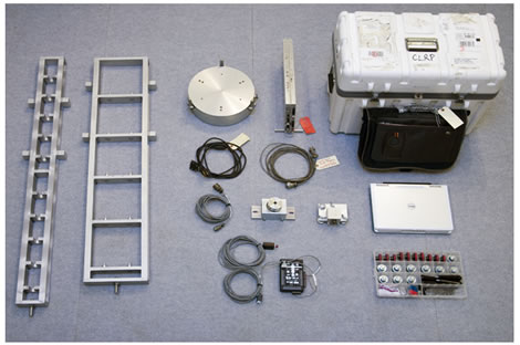
Sites for new FWD calibration centers must meet certain minimum specifications. Calibration center needs are well known and are based upon experience gained from the first 15 years of FWD calibration. Appendix F provides details about setting up the equipment found in figure 4, but certain basic operational issues must be discussed prior to ordering equipment and installing a test pad.
Figure 4. Photo. Calibration system hardware set.
Calibrating an FWD at a center controls or eliminates as many variables as possible by using the actual ground wave created by the FWD. Choosing an appropriate site at the center to install the test pad is important. A site should be large enough for the FWD and tow vehicle to be placed entirely indoors during calibration, which allows the calibrations to be performed year round. If possible, a trailer-mounted FWD should be driven into the facility prior to construction to ensure that the location is appropriate. In addition to the space, the site should have enough room to store and secure the FWD calibration equipment, including the testing stands, load cell, electronics, and the calibration computer. The computer can be a laptop or a desktop, but it should be dedicated to FWD calibration.
Once a site has been chosen, the test pad can be installed. Test pads are recommended to provide consistent deflections. If the test pads are built well, deflections will be consistent from season to season. Test pads can also be designed to provide larger deflections than might be found on normal industrial floors. Test pads that are 12 by 15 ft (4.0 by 4.5 m) are preferred, but 12- by 12-ft (4- by 4-m) pads are acceptable if space is limited. Test pad slabs must be accessible by all brands and models of FWDs. Space around the test pad should be sufficient for personnel to move and to allow the FWD to be maneuvered. A larger area is better, and at least 5 ft (2.5 m) of clear space is recommended on all sides. Table 1 lists the estimated cost for a new FWD calibration center.
| Component | Notes | Cost(1) |
|---|---|---|
| Accelerometer box AB-01 | Includes Silicon Designs Model 2220-5 accelerometer and cables | $1,600 |
| Geophone stand GCS-01 | Includes hardware for 10 Carl Bro and 10 JILS//Dynatest® geophone adapters |
$1,600 |
| Geophone adapters | Includes 10 adapters to mount KUAB geophones in GCS-01 stand | $200 |
| Seismometer stand SCS-01 | For up to 10 KUAB seismometers | $1,600 |
| Floor mount BJ-01 | Includes ball-joint and mounting clamp | $1,200 |
| Signal conditioner | Vishay 2310B and 2310-A20 | $2,200 |
| Data acquisition system | Keithley KUSB-3108, with cables to signal conditioner and computer | $1,250 |
| Load cell | Includes calibration certificate, cable, and shipping case | ±$11,000 |
| Computer | Laptop model with four USB ports | ±$1,500 |
| Total | $22,150 | |
|
(1)Prices current as of February 2009. Prices do not include shipping, installation, or training. |
||
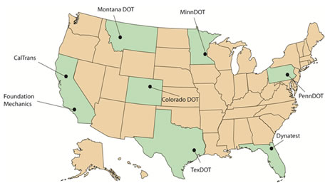
The pooled fund study provided support for upgrading all existing calibration centers in the United States. These included the centers operated by the Colorado Department of Transportation (CDOT), INDOT, Mn/DOT, PennDOT, and TxDOT (see figure 5). Installation and training has been provided to all centers. In addition, the calibration center operated by Dynatest® in Starke, FL, and the center operated by Main Roads Western Australia were also upgraded, although they are not part of the pooled fund study. The only existing center that has not been upgraded as of November 2010 is the center operated by the South African Bureau of Standards.
Figure 5. Map. Calibration center locations in the United States.
As a part of the upgrade, old beams and concrete blocks were removed, and new hardware equipment listed was installed (see table 1 and appendix E). Centers continued to use their existing test pads but with the new ball-joint anchor located close to the rear edge. New laptop computers were provided in most locations. During a 3-day training program, operators demonstrated their proficiency with the new procedure and were certified.
Calibration operators require training to use the equipment and software. Although training and certification only takes 3 days, it is recommended that new calibration operators also perform several trial calibrations prior to their first calibration for a client.
At the conclusion of the training, operators demonstrate their proficiency at carrying out the protocol detailed in appendix A, which is the same as the AASHTO R 32-09 procedure.(1) A certificate is issued to each operator who passes this review, and the certificate must be renewed annually during a QA visit. The procedures and checklists used during the QA visit are included in appendix D. All FWD calibrations must be conducted or supervised directly by a certified calibration technician.