U.S. Department of Transportation
Federal Highway Administration
1200 New Jersey Avenue, SE
Washington, DC 20590
202-366-4000
Federal Highway Administration Research and Technology
Coordinating, Developing, and Delivering Highway Transportation Innovations
 |
| This report is an archived publication and may contain dated technical, contact, and link information |
|
Publication Number: FHWA-HRT-05-068 Date: October 2005 |
The LTPP program was designed as a 20-year study of pavement performance. One aspect of the LTPP program is the GPS program, which monitors the performance of inservice pavement test sections. The length of a test section established for the LTPP program is 152.4 m (500 ft). In the LTPP program, JPC pavements are studied under the GPS-3 experiment.
Profile data collection is being performed at these test sections at regular intervals using an inertial profiler. The profile data collected at the test sections as well as IRI computed from the collected data are stored in the LTPP database. These data are an excellent source for investigating roughness progression of JPC sections.
The GPS-3 sections were established on inservice roads; therefore, the roughness of a test section immediately after construction is not known. The first IRI value available for a test section was obtained when the test section was first profiled after being accepted into the LTPP program.
For this study, the data of the GPS-3 test sections were obtained from the LTPP database in January 2003. The construction date of each test section was used to determine the pavement age corresponding to each profile date. The following two criteria were used for selecting GPS-3 sections for this analysis:
The first criterion was used because this study's emphasis was to analyze changes in roughness that occurred early in the life of the pavement. The second criterion ensured sufficient time-sequence IRI data were available to evaluate the progression of roughness over time.
Four different environmental zones are considered in the LTPP program: dry freeze, dry no-freeze, wet freeze, and wet no-freeze. The geographical regions corresponding to these environmental zones are shown in figure 23. The boundary between the wet and the dry zone generally corresponds to an annual precipitation of 508 mm (20 inches). The boundary between freezing and nonfreezing zones generally corresponds to an annual freezing index of 89 °Celsius (C) (192.2 °Fahrenheit (F)) days.
The distribution of the GPS-3 sections selected for analysis and classified according to the environmental zones and load transfer type is shown in table 1. Test sections were selected for the LTPP program in the late 1980s. Because there are only five doweled sections in the two dry regions, it appears that most JPC pavements at that time in the dry regions were nondoweled pavements.
Figure 23. Drawing. Environmental zones in the LTPP program.
| Environmental Zone | Number of Sections | ||
|---|---|---|---|
| Doweled | Nondoweled | Total | |
| Dry freeze | 3 | 12 | 15 |
| Dry no-freeze | 2 | 4 | 6 |
| Wet freeze | 14 | 16 | 30 |
| Wet no-freeze | 13 | 1 | 14 |
| Total | 32 | 33 | 65 |
All doweled sections were paved with a slipform paver, except for one section where side forms were used. All nondoweled sections were also paved with a slipform paver, except for four sections where side forms were used.
A linear regression analysis was performed for each GPS-3 section using the time-sequence IRI data to obtain a rate of change of IRI. Based on the rate of change of IRI, the test sections were divided into three data sets:
Roughness trends for each data set were studied separately for nondoweled and doweled pavements.
Thirty-three nondoweled sections were available for analysis. Table 2 shows the number of test sections in each data set, classified by environmental zone. The GPS section numbers of these sections are shown in table 74, which is in appendix B.
| Data Set | Number of Sections | |||||
|---|---|---|---|---|---|---|
| Environmental Zone | Total | Percentage of Total Doweled Sections | ||||
| Wet Freeze | Wet No-Freeze | Dry No-Freeze | Dry Freeze | |||
| 1 | 5 | 1 | 3 | 2 | 11 | 33 |
| 2 | 4 | 0 | 1 | 6 | 11 | 33 |
| 3 | 7 | 0 | 0 | 4 | 11 | 33 |
Roughness progression plots for the sections in each data set are shown in figures 24-26. Each line in a graph represents a pavement section, and the points on a line represent the pavement age and the corresponding roughness of the test section. An evaluation of roughness progression at test sections indicated that some sections showed variability in IRI between the years, and IRI during a particular year sometimes was lower than that for the previous year. This type of condition can occur because of slab curling and warping effects or shrink/swell effects of subgrade that can change the profile of the pavement.
The average IRI of all sections in each data set at the first and the last profile dates as well as the corresponding average pavement ages are shown in table 3. Note that many of these sections are still being monitored, and the last profile date was the one available when data were obtained from the database for this analysis.
| Data Set | Average Pavement Age (Years) | Average IRI (m/km) | ||
|---|---|---|---|---|
| First Profile Date | Last Profile Date | First Profile Date | Last Profile Date | |
| 1 | 5.6 | 16.8 | 1.33 | 1.40 |
| 2 | 3.8 | 14.9 | 1.38 | 1.69 |
| 3 | 6.0 | 16.9 | 1.63 | 2.69 |
1 m/km = 63.4 inches/mi
Figure 24. Chart. Roughness progression of nondoweled sections, rate of change of IRI less than 0.02 meters per kilometer per year.

Figure 25. Chart. Roughness progression of nondoweled sections, rate of change of IRI between 0.02 and 0.04 meters per kilometer per year.

Figure 26. Chart. Roughness progression of nondoweled sections, rate of change of IRI greater than 0.04 meters per kilometer per year.

The average IRI at the first profile date for the pavements in data sets 1 and 2 were close to each other. The average IRI at the first profile date for the pavements in data set 3 was higher than data sets 1 and 2. The pavements that fell into data set 1 have shown very little change in IRI over the monitored period. The average IRI of the pavements in data set 2 have increased from 1.38 to 1.68 m/km (87 to 107 inches/mi) over an 11-year period. At the last profile date, the pavements in data set 3 have an average age of 16.9 years and an average IRI of 2.69 m/km (171 inches/mi), which indicates that these pavements have reached an unacceptable roughness level well before the end of their intended service life.
The average IRI of the pavements that fell into data set 2 at the first profile date was 1.38 m/km (87 inches/mi), and the average age of the pavements at that time was 3.8 years. If a pavement has a rate of increase of IRI of 0.04 m/km/yr (2.54 inches/mi/yr) over a 16-year period, the change in roughness would be 0.64 m/km (41 inches/mi). Based on this rate of increase of roughness, the average IRI of the pavements in data set 2 when the pavements are 20 years old is expected to be 2.02 m/km (128 inches/mi). This is a typical IRI of a pavement after a 20-year life. Hence, pavements that fell into data set 2 are performing as expected, pavements in data set 1 are providing a better performance than expected, and pavements in data set 3 are showing a poor performance.
Thirty two doweled sections were available for analysis. Table 4 shows the number of test sections in each data set, classified by environmental zone. The GPS section number of these sections is shown in table 75, which is in appendix B.
| Data Set | Number of Sections | |||||
|---|---|---|---|---|---|---|
| Environmental Zone | Total | Percentage of Total Doweled Sections | ||||
| Wet Freeze | Wet No-Freeze | Dry No-Freeze | Dry Freeze | |||
| 1 | 8 | 8 | 1 | 1 | 18 | 56 |
| 2 | 3 | 3 | 1 | 1 | 8 | 25 |
| 3 | 3 | 2 | 0 | 1 | 6 | 19 |
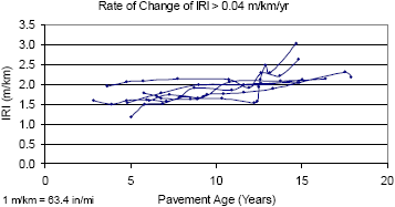
Roughness progression plots for the pavements in each data set are shown in figures 27-29. The average IRI of all sections in each data set at the first and the last profile dates as well as the corresponding average pavement ages are shown in table 5.
The average IRI at the first profile date for the data set 1 pavements was higher than for data set 2. Several sections in data set 1 had high IRI values that caused the IRI at the first profile date to be high. The average IRI of the pavements in data set 3 at the first profile date was higher than for data set 2, but similar to data set 1.
Figure 27. Chart. Roughness progression of doweled sections, rate of change of IRI less than 0.02 meters per kilometer per year.
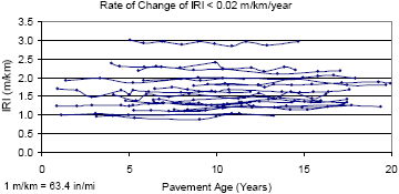
Figure 28. Chart. Roughness progression of doweled sections, rate of change of IRI between 0.02 and 0.04 meters per kilometer per year.
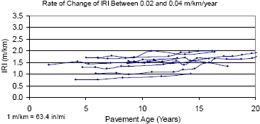
Figure 29. Chart. Roughness progression of doweled sections, rate of change of IRI greater than 0.04 meters per kilometer per year.
| Data Set | Average Pavement Age (Years) | Average IRI (m/km) | ||
|---|---|---|---|---|
| First Profile Date | Last Profile Date | First Profile Date | Last Profile Date | |
| 1 | 5.1 | 16.1 | 1.64 | 1.66 |
| 2 | 5.6 | 16.8 | 1.36 | 1.67 |
| 3 | 4.7 | 15.6 | 1.60 | 2.35 |
1 m/km = 63.4 inches/mi
The pavements in data set 1 have shown very little change in IRI over the monitored period. The average IRI of the pavements in data set 2 have increased from 1.36 to 1.67 m/km (86 to 106 inches/mi) over an 11-year period. At the last profile date, the pavements in data set 3 have an average age of 15.6 years and an average IRI of 2.35 m/km (149 inches/mi), which indicates that these pavements have reached an unacceptable roughness level well before the end of their intended service life. The average IRI of the pavements in data set 2 at the first profile date was 1.36 m/km (86 inches/mi); the average age was 5.6 years. If a pavement has a rate of increase of IRI of 0.04 m/km/yr (2.54 inches/mi/yr) over a 15-year period, the change in roughness would be 0.64 m/km (41 inches/mi). Based on this rate of increase of roughness, the average IRI of the pavements in data set 2 when the pavements are 20 years old is expected to be 2.00 m/km (127 inches/mi). This is a typical IRI of a pavement after a 20-year service life. Hence, the pavements in data set 2 are behaving as expected, the pavements in data set 1 are performing much better than expected, and the pavements in data set 3 have performed poorly.
The percentage of sections for doweled and nondoweled pavements in each data set is shown in table 6. As seen in this table, 56 percent of the doweled sections were in data set 1, compared to 33 percent for nondoweled sections. Nineteen percent of doweled sections fell into data set 3, compared to 33 percent for the nondoweled sections.
| Data Set | Rate of Change of Roughness (m/km/yr) | Percentage of Sections | |
|---|---|---|---|
| Doweled | Nondoweled | ||
| 1 | <0.02 | 56 | 33 |
| 2 | 0.02 to 0.04 | 25 | 33 |
| 3 | >0.04 | 19 | 33 |
1 m/km = 63.4 inches/mi
These data clearly show that doweled and nondoweled pavements have different roughness progression characteristics. Generally, doweled pavements show much less roughness progression compared to nondoweled pavements.
Fault measurements at the GPS-3 test sections are obtained at regular time intervals; measurements are obtained along the pavement edge and the right wheel path at each joint and crack. For each test section, the fault measurement date closest to the last profile date was identified in the database. Then, the fault data measured along the right wheel path corresponding to the identified date were extracted from the database.
Faulting data were available for 31 of the 33 nondoweled sections and for all doweled sections. The fault values recorded at joints and cracks were added together to obtain the total faulting for each section. Table 76, which is in appendix C, shows the fault values for all nondoweled sections. This table also shows the following parameters for each test section: last profile date, IRI for last profile date, the fault survey date closest to the last profile date, and the total faulting at the joints and the cracks.
Except for the following few cases, the faulting occurred at the joints and not at the cracks. For nondoweled sections, faulting at the cracks was recorded only at two sections each in data sets 2 and 3. For these four sections, the total faulting within the test section at cracks was less than 5 mm (0.2 inch). For doweled sections, the faulting at cracks was recorded only at two sections. The magnitude of the total faulting within the section at cracks was 2 and 43 mm (0.08 and 1.69 inches) at the two sections.
The relationship between roughness and faulting is discussed separately (below) for nondoweled and doweled pavements.
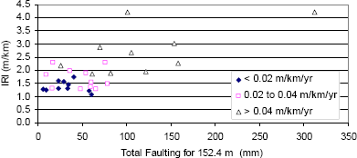
Figure 30 shows the relationship between IRI at last profile date and the total faulting at the test sections; separate symbols are used for the different data sets. This figure shows a trend of higher roughness that corresponds with increasing faulting. The correlation coefficient between the IRI at last profile date and faulting was 0.70.
The average total faulting for data sets 1 through 3 were 32, 47, and 119 mm (1.26, 1.85, and 4.69 inches), respectively. Pavement sections in data set 3 had high faulting. Faulting data were available for 10 of the 11 sections in data set 3, with 6 of these sections each having total faulting greater than 100 mm (4 inches).
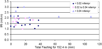
Figure 31 shows the relationship between IRI at last profile date and total faulting at the test sections; separate symbols are used for the different data sets. No relationship between IRI and faulting is seen in this figure. The correlation coefficient between IRI at last profile date and total faulting was 0.07.
Figure 30. Chart. Relationship between IRI and faulting for nondoweled pavements.
1 m = 3.28 ft
1 m/km = 63.4 inches/mi
Figure 31. Chart. Relationship between IRI and faulting for doweled pavements.
1 m = 3.28 ft
1 m/km = 63.4 inches/mi
The average total faulting for data sets 1 through 3 were 15, 13, and 38 mm (0.59, 0.51, and 1.50 inches), respectively. Two sections in data set 3 had total faulting values in excess of 40 mm (1.57 inches), and if the faulting at these two sections were omitted, the average faulting of the sections in data set 3 would be 14 mm (0.55 inches).
A clear relationship between IRI and faulting was observed for nondoweled pavements. This type of relationship was not seen for doweled pavements.
Of the 32 doweled sections, 30 sections (94 percent) had a total faulting that was less than 38 mm (1.50 inches), whereas only 39 percent of the nondoweled sections met this comparison. These data show that dowels served their intended function by providing load transfer between slabs and prevented faulting.
The LTPP database has profile data for five profiler runs for each profiling date. For each analyzed GPS section, one profile run was selected from the first profile date and last profile date. The CI of the PCC slabs of the selected profile data sets was computed using the method developed by Byrum,(10) described in appendix A. Changes in slab curvatures that have occurred over the monitored period, and the relationship between change in roughness and change in curvature, were examined separately for nondoweled and doweled pavements.
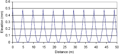
A theoretical evaluation of the effect of pure curvature of PCC slabs on IRI was performed by generating profiles having different curvature (where curvature is equal to reciprocal of radius) for three different slab lengths and then computing the IRI values. Figure 32 shows an example of a theoretically generated profile for a PCC pavement with a 4.9-m (16-ft) joint spacing that has a curvature of 0.16 x 10⁻³ 1/m (0.049 x 10⁻³ 1/ft).
Figure 32. Chart. Theoretically generated slab profiles.
1 mm = 0.039 inch
1 m = 3.28 ft
Figure 33 shows the relationship between curvature and IRI for slab lengths of 4.9, 6.1, and 7.3 m (16, 20, and 24 ft) that was obtained from this theoretical evaluation.
The actual curvature behavior of PCC slabs is not expected to follow the shapes generated in this theoretical analysis. In a pavement, the middle portion of the slab will be in contact with the ground with curling being confined to the slab portions close to the joints. However, this example illustrates that slab curvature can have a significant effect on IRI.
Figure 33. Chart. Relationship between curvature and IRI from theoretical analysis.

1 m/km = 63.4 inches/mi
1/m = 1/3.28 ft
This example described the effect of pure curvature on IRI. The CI computed in this study is based on an average curvature computed for all slabs within the section; the average curvature is the average of curvature values computed using different arc lengths (see appendix A). A high value of CI indicates that a high level of slab curling or warping is present in the PCC slabs.
The CI values for the first profile date and the last profile date for all nondoweled sections are presented in table 78, which is in appendix D. Figure 34 shows a box plot of the distribution of CI values for the last profile date for the three data sets. Table 7 shows the median, 25th percentile, and 75th percentile values of CI at the last profile date. The median CI for all three data sets was positive (slab curved upwards). The CI values of pavements in data set 3 were much higher than those for data sets 1 and 2.
The change in CI that has occurred between the first and last profile dates was examined separately for the three data sets. Figures 35-37 show box plots of the CI at the first and last profile date for data sets 1 through 3.
For data set 1, the median CI for the first and last profile dates were 0.048 x 10⁻³ and 0.066 x 10⁻³ 1/m (0.015 x 10⁻³ and 0.020 x 10⁻³ 1/ft), respectively. The range of CI between the 25th and 75th percentile values for the first and last profile dates was -0.007 x 10⁻³ to 0.141 x 10⁻³ 1/m (-0.002 x 10⁻³ to 0.043 x 10⁻³ 1/ft) and -0.037 x 10⁻³ to 0.173 x 10⁻³ 1/m (-0.011 x 10⁻³ to 0.053 x 10⁻³ 1/ft), respectively. Little change in CI has occurred for the pavements in data set 1.
For data set 2, the median CI for the first and last profile dates were 0.030 x 10⁻³ and 0.127 x 10⁻³ 1/m (0.009 x 10⁻³ and 0.039 x 10⁻³ 1/ft), respectively. The range of CI between the 25th and 75th percentile values for the first and last profile dates was -0.047 x 10⁻³ to 0.135 x 10⁻³ 1/m (-0.014x 10⁻³ to 0.041 x 10⁻³ 1/ft) and 0.009 x 10⁻³ to 0.273 x 10⁻³ 1/m (0.003 x 10⁻³ to 0.083 x 10⁻³ 1/ft), respectively. These data show that the CI range of the pavements in data set 2 has increased over the monitored period.
Figure 34. Box Plot. Distribution of CI at last profile date for nondoweled pavements.
1 m/km = 63.4 inches/mi
1/m = 1/3.28 ft
| Data Set | Curvature Index x 1,000 (1/m) | ||
|---|---|---|---|
| Median | 25thPercentile | 75thPercentile | |
| 1 | 0.055 | -0.037 | 0.173 |
| 2 | 0.127 | 0.009 | 0.273 |
| 3 | 0.822 | 0.411 | 0.962 |
Figure 35. Box Plot. Distribution of CI for nondoweled data set 1.
1 m/km = 63.4 inches/mi
1/m = 1/3.28 ft
Figure 36. Box Plot. Distribution of CI for nondoweled data set 2.
1 m/km = 63.4 inches/mi
1/m = 1/3.28 ft
Figure 37. Box Plot. Distribution of CI for nondoweled data set 3.
1 m/km = 63.4 inches/mi
1/m = 1/3.28 ft
For data set 3, the median CI for the first and last profile dates were 0.287 x 10⁻³ and 0.822 x 10⁻³ 1/m (0.088 x 10⁻³ and 0.251x 10⁻³ 1/ft), respectively. The range of CI between the 25th and 75th percentile values for the first and last profile dates were 0.005 x 10⁻³ to 0.433 x 10⁻³ 1/m (0.002 x 10⁻³ to 0.132 x 10⁻³ 1/ft) and 0.411 x 10⁻³ to 0.962 x 10⁻³ 1/m (0.125 x 10⁻³ to 0.293 x 10⁻³ 1/ft), respectively. These data show that the CI of pavements in data set 3 has greatly increased over the monitored period.
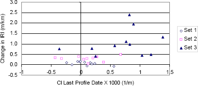
Figure 38 shows the relationship between the change in IRI between the first and last profile dates and CI at the last profile date. This plot shows that 73 percent of sections have a positive curvature at the last profile date. Sections with higher CI (either positive or negative) are generally associated with high changes in IRI.
Figure 38. Chart. Change in IRI and CI at last profile date for nondoweled sections.
1 m/km = 63.4 inches/mi
1/m = 1/3.28 ft
A correlation analysis was carried out to identify concrete material parameters and environmental parameters that could be related to CI. In addition, scatterplots between the CI at last profile date and each parameter were examined to investigate the relationship between the two factors. This procedure was used to examine whether a relationship existed between the two parameters, because the correlation coefficient can sometimes be significantly influenced by outliers. Based on this investigation, the factors that had the strongest relationship to CI are shown in table 8.
| Factor | Correlation Coefficient |
|---|---|
| Coefficient of thermal expansion | 0.69 |
| Freezing index | 0.43 |
| Total faulting at site | 0.42 |
| Weight of cement in mix | -0.34 |
| Mean annual temperature | -0.30 |
| Annual precipitation | -0.29 |
| Elastic modulus of concrete | 0.28 |
| Number of days below 0 °C (32 °F)per year | 0.28 |
| Number of wet days per year | -0.22 |
| Split tensile strength of concrete | 0.21 |
| PCC slab thickness | -0.20 |
Higher values of the following parameters were associated with higher CI values: coefficient of thermal expansion (CTE), freezing index, total faulting at site, elastic modulus of concrete, number of days in a year below 0 °C (32 °F), and split tensile strength of concrete. Higher values of the following parameters were associated with lower CI values: weight of cement in mix, mean annual temperature, annual precipitation, number of wet days per year, and PCC slab thickness.
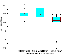
The CI values for the first profile date and the last profile date for all doweled sections are presented in table 79, which is in appendix D. Figure 39 shows a box plot of the distribution of CI values for the last profile date. Table 9 shows the median, 25th percentile, and 75th percentile values of CI at the last profile date.
Figure 39. Distribution of CI at last profile date for doweled pavements.
1 m/km = 63.4 inches/mi
1/m = 1/3.28 ft
| Data Set | Curvature Index x 1,000 (1/m) | ||
|---|---|---|---|
| Median | 25th Percentile | 75th Percentile | |
| 1 | -0.020 | -0.126 | 0.045 |
| 2 | -0.043 | -0.181 | 0.247 |
| 3 | -0.402 | -0.465 | -0.253 |
1/m = 1/3.28 ft
The median CI for all three data sets was negative (downward curvature), with the median CI decreasing for data sets 1 through 3. The median CI for data sets 1 and 2 was close to zero, indicating negligible curvature. Most CI values for data set 1 were within a relatively narrow range. The range of CI for data set 2 was wider than that for data set 1. All sections in data set 3 had negative CI values.
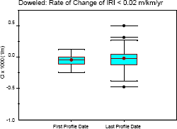
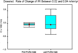
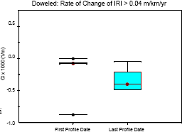
The changes in CI that occurred between the first and last profile dates were examined separately for the three data sets. Figures 40 through 42 show box plots of the CI at the first and last profile date for data sets 1 through 3.
For data set 1, the median CI for the first and last profile dates were -0.045 x 10⁻³ and -0.020 x 10⁻³ 1/m (-0.137 x 10⁻³ and -0.006 x 10⁻³ 1/ft), respectively. The range of CI between the 25th and 75th percentile values for the first and last profile dates were -0.104 x 10⁻³ to 0.003 x 10⁻³ 1/m (-0.032 x 10⁻³ to 0.001 x 10⁻³ 1/ft) and -0.126 x 10⁻³ to 0.045 x 10⁻³ 1/m (-0.038 x 10⁻³ to 0.014 x 10⁻³ 1/ft), respectively. Little change in CI has occurred for the majority of pavements in this data set.
Figure 40. Distribution of CI for doweled data set 1.
1 m/km = 63.4 inches/mi
1/m = 1/3.28 ft
Figure 41. Distribution of CI for doweled data set 2.
1 m/km = 63.4 inches/mi
1/m = 1/3.28 ft
For data set 2, the median CI for the first and last profile dates were -0.033 x 10⁻³ and -0.043 x 10⁻³ 1/m (-0.010 x 10⁻³ and -0.013 x 10⁻³ 1/ft), respectively. The range of CI between the 25th and 75th percentile values for the first and last profile dates were -0.062 x 10⁻³ to -0.011 x 10⁻³ 1/m (-0.019 x 10⁻³ to -0.003 x 10⁻³ 1/ft) and -0.181 x 10⁻³ to 0.247 x 10⁻³ 1/m (-0.055 x 10⁻³ to 0.075 x 10⁻³ 1/ft), respectively. At the first profile date, the CI values encompassed a very narrow range. However, the CI values at the last profile date encompassed a much wider range, with the range increasing both negatively and positively.
Figure 42. Distribution of CI for doweled data set 3.
1 m/km = 63.4 inches/mi
1/m = 1/3.28 ft
For data set 3, the median CI for the first and last profile dates were -0.073 x 10⁻³ and -0.402 x 10⁻³ 1/m (-0.022 x 10⁻³ and -0.122 x 10⁻³ 1/ft), respectively. The range of CI between the 25th and 75th percentile values for the first and last profile dates were -0.080 x 10⁻³ to -0.021 x 10⁻³ 1/m (-0.024 x 10⁻³ to -0.006 x 10⁻³ 1/ft) and -0.465 x 10⁻³ to -0.253 x 10⁻³ 1/m (-0.142 x 10⁻³ to -0.077 x 10⁻³ 1/ft). At the first profile date, the CI values encompassed a very narrow range with all sections having a negative curvature except for one section that showed a very slight positive curvature. However, at the last profile date all sections in this data set showed a negative (downward) curvature with the magnitude of downward curvature having increased significantly over time for a majority of the sections.
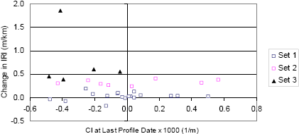
Figure 43 shows the relationship between the change in IRI between the first and last profile dates and the CI at the last profile date. GPS section 273003 had the largest negative curvature with a CI of -1.64 x 10⁻³ 1/m (-0.5 x 10⁻³ 1/ft), and this data point is not shown in figure 43. This plot shows that 63 percent of the sections have a negative curvature. There was no clear relationship between CI at last profile date and change in IRI.
Figure 43. Change in IRI and CI at last profile date for doweled pavements.
1 m/km = 63.4 inches/mi
1/m = 1/3.28 ft
Because a majority of doweled pavements at the last profile date had a negative curvature, an investigation was performed to identify parameters having a correlation with negative CI values. This analysis was performed using scatterplots and by computing correlation coefficients between CI and concrete material parameters and environmental parameters. Table 10 shows the parameters that had the strongest relationship with negative CI values.
Higher values of the following parameters resulted in more downward curvature: freezing index, number of days in a year below 0 °C (32 °F), ratio between PCC elastic modulus and split tensile strength, and weight of cement in mix. Higher values of the following parameters resulted in lower downward curvature: mean annual temperature, annual precipitation, days in year with temperature greater than 32 °C (90 °F), and PCC slab thickness.
| Factor | Correlation Coefficient |
|---|---|
| Freezing index | -0.51 |
| Mean annual temperature | 0.49 |
| Number of days below 0 °C (32 °F) per year | -0.44 |
| Ratio between PCC elastic modulus and tensile strength | -0.39 |
| Weight of cement in mix | -0.39 |
| Annual precipitation | 0.37 |
| Days in year with temperature greater than 32 °C(90 °F) | 0.35 |
| PCC slab thickness | 0.27 |
At the last profile date, 73 percent of nondoweled pavements had a positive curvature; 63 percent of the doweled sections had a negative curvature. The dowels appear to be restraining the slabs in PCC pavements and limiting the magnitude of the upward curvature. Overall, the nondoweled pavements had higher curvature than doweled pavements. The pavements in data set 3 for nondoweled pavements showed a significant increase in upward curvature over the monitored period. A few pavements in data set 3 for doweled pavements showed an increase in downward curvature over the monitored period. For nondoweled pavements, a strong relationship was seen between faulting and slab curvature. It appears that high slab curvature in these pavements increases the potential for faulting and results in a high magnitude of faulting.
The effect of faulting and slab curvature on roughness was analyzed previously. In this section, the effect of pavement design factors, traffic, environmental conditions, and concrete properties on roughness progression are evaluated. The data available in the LTPP database were reviewed to select parameters that could be studied under each of these factors. The parameters considered for analysis are shown in table 11.
| Factor | Parameter |
|---|---|
| Pavement design | |
| Slab thickness | |
| Base type | |
| Joint spacing | |
| Drainage | |
| Shoulder | |
| Traffic | Cumulative axle loads |
| Environmental Conditions | |
| Annual precipitation | |
| Annual wet days | |
| Mean annual temperature | |
| Number of days with temperature < 0 °C (32 °F), per year | |
| Number of days with temperature > 32 °CC, (90 °CF), per year | |
| Annual freezing index | |
| Freeze thaw cycles per year | |
| Concrete Properties | |
| Split tensile strength | |
| Elastic modulus | |
| Compressive strength | |
| Coefficient of thermal expansion | |
| Weight of cement in mix | |
| Weight of fine aggregate in mix | |
| Weight of coarse aggregate in mix | |
| Water-to-cement ratio | |
| Unit weight of concrete |
The correlation coefficient between the change in roughness and each parameter shown in table 11 were computed separately for nondoweled and doweled pavements. Scatterplots between the change in roughness and each parameter were also plotted to examine the relationship between the two factors. This procedure was used because high correlation coefficients can sometimes be obtained due to outliers. The factors that had the highest correlation to change in roughness for nondoweled pavements that were reasonable based on the relationship seen in the scatterplots are shown in table 12. No strong correlations or trends were noted for the doweled pavements.
A further evaluation of the effect of parameters listed in table 11 on roughness progression was performed separately for doweled and nondoweled pavements. For nondoweled pavements, the three data sets established previously were used to compare differences in parameters between the three data sets. A meaningful analysis using a similar approach cannot be performed for doweled pavements because there were only a few sections in data sets 2 and 3 (eight and six sections, respectively). Therefore, doweled pavements were analyzed by dividing the pavement sections into two groups, with the first group containing data set 1 and the second group containing data sets 2 and 3.
| Factor | Correlation Coefficient |
|---|---|
| Freezing index | 0.51 |
| Number of days below 0 °C (32 °F) per year | 0.48 |
| Mean annual temperature | -0.48 |
| Freeze thaw cycles per year | 0.35 |
| Joint spacing | 0.31 |
| Number of days above 0 °C (32 °F) per year | -0.30 |
The results of the analysis for pavement design factors, traffic, environmental conditions, and concrete properties are shown separately.
The effect of the following pavement design factors on roughness progression was investigated: concrete slab thickness, base type, joint spacing, drainage, and shoulder type.
Concrete Slab Thickness
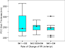
The distribution of the PCC slab thickness for the nondoweled data sets is shown in figure 44. The median PCC thickness for pavements in data sets 1, 2, and 3 were 244, 254, and 245 mm (9.6, 10, and 9.7 inches), respectively. Above the median value, the PCC slab thickness for pavements in data set 1 had a much wider range than for data sets 2 and 3.
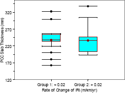
The distribution of the PCC slab thickness for the doweled data sets is shown in figure 45. The median PCC thickness for pavements in groups 1 and 2 were 237 and 236 mm (9.33 and 9.29 inches), respectively. However, the range of thickness below the median for group 2 pavements was much more than that for group 1 pavements.
The PCC slab thickness for both nondoweled and doweled pavements would have been selected based on the expected traffic volumes. If the pavements in data sets 2 and 3 for nondoweled pavements and group 2 for doweled pavements were subjected to a much higher traffic level than the design traffic level, it would be a factor contributing to higher roughness. The relationship between traffic levels and pavement thickness will be discussed in a later section.
Figure 44. Distribution of PCC slab thickness for nondoweled pavements.
1 m/km = 63.4 inches/mi
1/m = 1/3.28 ft
Figure 45. Distribution of PCC slab thickness for doweled pavements.
1 m/km = 63.4 inches/mi
1/m = 1/3.28 ft
Base Type
The base type for nondoweled pavements was available for eight sections in data set 1, for all sections in data set 2, and for nine sections in data set 3. Table 13 shows the distribution of base types for each data set.
The base type for doweled pavements was available for 17 sections in group 1 and 13 sections in group 2. Table 14 shows the distribution of base type for the two groups. The base types for the six doweled sections that had a rate of increase of IRI greater than 0.04 m/km/yr (2.54 inches/mi/yr) were as follows: two sections, gravel base; three sections, cement-treated base; and one section, asphalt-treated base.
| Data Set | Number of Sections | |||
|---|---|---|---|---|
| Gravel Base | Cement-Treated Base | Asphalt-Treated Base | Total | |
| 1 | 3 | 3 | 2 | 8 |
| 2 | 5 | 5 | 1 | 11 |
| 3 | 3 | 5 | 1 | 9 |
| Data Group | Number of Sections | |||
|---|---|---|---|---|
| Gravel Base | Cement-Treated Base | Asphalt-Treated Base | Total | |
| 1 | 7 | 8 | 2 | 17 |
| 2 | 5 | 6 | 2 | 13 |
No conclusion on the effect of base type on roughness progression can be made for either doweled or nondoweled pavements.
Joint Spacing
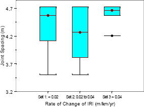
The distribution of the joint spacing for nondoweled data sets is shown in figure 46. Five pavement sections each in data sets 1 and 2 had a joint spacing between 4.6 and 4.7 m (15.1 and 15.4 ft). All sections in data set 3 had a joint spacing of either 4.6 or 4.7 m (15.1 and 15.4 ft) except for one section that had a joint spacing of 4.2 m (13.8 ft). These data suggest that higher joint spacing in nondoweled pavements may be a factor contributing to higher roughness.
Figure 46. Distribution of joint spacing for nondoweled pavements.
1 m/km = 63.4 inches/mi
1/m = 1/3.28 ft
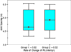
The distribution of joint spacing for the doweled data groups is shown in figure 47. The median joint spacing for the pavements in data groups 1 and 2 were 4.8 and 5.3 m (15.7 and 17.4 ft), respectively. The overall range of joint spacing for the two data groups was similar, and no conclusion could be made on the effect of joint spacing on roughness for doweled pavements.
Figure 47. Distribution of joint spacing for doweled pavements.
1 m/km = 63.4 inches/mi
1/m = 1/3.28 ft
Drainage
The LTPP database indicates the type of drainage provided at each test section. The following drainage information on nondoweled sections was determined from the data available in the database:
The drainage information for the doweled sections was as follows:
The subgrade type at the sections may have been a consideration in deciding whether drainage was provided at a section. In cases where coarse-grained subgrade was present at a site, a decision may have been made not to provide drainage. An evaluation of the subgrade information for nondoweled sections indicated the following:
An evaluation of the subgrade information for doweled sections indicated the following:
No conclusions on the effect of provision of drainage on roughness progression could be made based on this information.
Shoulder Type
The shoulder type for the nondoweled sections is shown in table 15. The shoulder type was not specified for one section in data set 1. The median width of the paved shoulder for all three data sets was 3 m (9.8 ft).
| Data Set | Number of Sections | ||
|---|---|---|---|
| Gravel Shoulder | Concrete Shoulder | Asphalt Shoulder | |
| Set 1 | 0 | 3 | 7 |
| Set 1 | 0 | 5 | 6 |
| Set 1 | 1 | 2 | 8 |
The shoulder type for the doweled test sections is shown in table 16. The average widths of the paved shoulder for pavements in groups 1 and 2 were 2.3 and 2.6 m (7.5 and 8.5 ft), respectively. The shoulder information was not specified for two sections each in data groups 1 and 2. For the doweled pavements that had the rate of increase of IRI greater than 0.04 m/km (2.54 inches/mi), the shoulder types were as follows: one section, turf; two sections, granular; one section, asphalt; and two sections, concrete.
No effect of the shoulder type on roughness progression could be concluded based on these data.
| Data Group | Number of Sections | ||
|---|---|---|---|
| Gravel Shoulder | Concrete Shoulder | Asphalt Shoulder | |
| 1 | 2 | 8 | 6 |
| 2 | 4 | 5 | 3 |
The traffic information available in the LTPP database was analyzed to obtain an estimate of the ESALs applied on the pavement the first year after the pavement was opened to traffic and to obtain a traffic growth rate. The method presented by Byrum and Kohn was used to obtain these values.(35) Thereafter, these values were used to compute the cumulative ESALs each test section has received at the last profile date.
Tables 17 and 18 show the distribution of cumulative traffic for the nondoweled and doweled sections, respectively. These tables indicate that some sections showing little increase in roughness have carried a significant amount of traffic. Conversely, some sections that have carried lower traffic volumes are showing a high rate of increase of IRI.
| Cumulative ESALs | Number of Sections | ||
|---|---|---|---|
| Data Set 1 | Data Set 2 | Data Set 3 | |
| < 2.5 million | 3 | 3 | 3 |
| 2.5 to 5 million | 1 | 4 | 4 |
| 5 to 7.5 million | 1 | 2 | 0 |
| 7.5 to 10 million | 0 | 1 | 1 |
| > 10 million | 6 | 1 | 4 |
| Cumulative ESALs | Number of Sections | |
|---|---|---|
| Data Set 1 | Data Set 2 | |
| < 2.5 million | 8 | 3 |
| 2.5 to 5 million | 2 | 6 |
| 5 to 7.5 million | 4 | 3 |
| 7.5 to 10 million | 1 | 1 |
| > 10 million | 3 | 2 |
The relationship between cumulative traffic and PCC slab thickness for nondoweled and doweled sections is shown in figures 48 and 49, respectively. These figures show that the sections showing high rates of increase of roughness have not necessarily been subjected to very high traffic volumes.
Figure 48. Slab thickness versus cumulative traffic for nondoweled pavements.
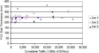
1 mm = 0.039 inch
Figure 49. Slab thickness versus cumulative traffic for doweled pavements.
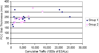
1 mm = 0.039 inch
The effect of annual precipitation, mean annual air temperature, and freezing index on roughness progression was investigated.
Annual Precipitation
The distribution of annual precipitation at nondoweled and doweled sections is shown in figures 50 and 51, respectively. The median annual precipitation for nondoweled data sets 1, 2 and 3 was 530, 469, and 530 mm (20.9, 18.5, and 20.9 inches), respectively. The median annual precipitation for doweled groups 1 and 2 were 1,130 and 1,034 mm (44.5 and 40.7 inches), respectively. No specific effect of precipitation on roughness progression was noted for either doweled or nondoweled sections.
Figure 50. Distribution of annual precipitation for nondoweled pavements.
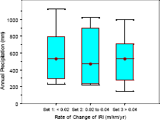
1 mm = 0.039 inch
1 m/km = 63.4 inches/mi
Figure 51. Distribution of annual precipitation for doweled pavements.
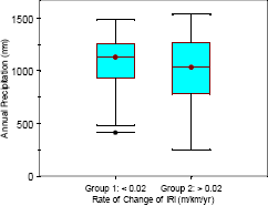
1 mm = 0.039 inch
1 m/km = 63.4 inches/mi
Mean Temperature
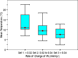
The distribution of mean annual air temperature for the nondoweled data sets is shown in figure 52. The median temperature for the nondoweled data sets 1, 2, and 3 was 11, 9.5, and 7.6 °C (52, 49, and 46 °F), respectively. The data show that nondoweled pavements in climates having lower mean temperatures have performed poorly compared to those in areas having a higher mean temperature. In nondoweled pavements, load transfer is provided by aggregate interlock. Higher temperatures result in better load transfer, thus reducing faulting and the chances of other distresses occurring at the joints. This situation in turn results in a lower roughness.
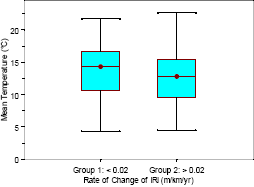
Figure 53 shows the distribution of mean annual air temperatures for the doweled data sets. The median temperature for doweled groups 1 and 2 was 14.3 and 12.8 °C (58 and 55 °F), respectively. No strong effect of mean temperature on roughness progression was observed for the doweled data set, although the range of temperatures between the 25th and 75th percentile values was higher for group 1 compared to group 2.
Trends similar to that observed for mean temperature were seen for the nondoweled and doweled pavements when the effect of number of days above 32 °C (90 °F) on roughness progression was evaluated.
Figure 52. Distribution of mean annual temperature for nondoweled pavements.
°F = 1.8(°C) + 32
1 m/km = 63.4 inches/mi
Figure 53. Distribution of mean annual temperature for doweled pavements.
°F = 1.8(°C) + 32
1 m/km = 63.4 inches/mi
Freezing Index
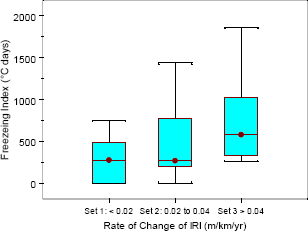
The distribution of freezing index for the nondoweled data sets is shown in figure 54. The median freezing index for data sets 1, 2, and 3 was 278, 271, and 581 °C days (532.4, 519.8, and 1,077.8 °F days), respectively. Figure 54 shows that pavements in areas having lower freezing indices perform better than those in higher freezing index areas. Areas having higher freezing indices will also have lower temperatures that affect the load transfer capability in nondoweled pavements, resulting in poorer pavement performance. In addition, greater roughness can occur in high freezing index areas due to frost effects, if a frost susceptible base or subgrade is present below the PCC slab.
Figure 54. Distribution of freezing index for nondoweled pavements.
°F = 1.8(°C) + 32
1 m/km = 63.4 inches/mi
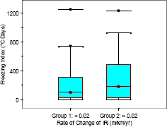
The distribution of freezing index for the doweled pavements is shown in figure 55. The median freezing index for pavements in groups 1 and 2 was 99 and 179 °C days (210 and 354 °F days), respectively. As shown in this figure, group 1 pavements overall have a lower freezing index than group 2 pavements, which indicates that pavements located in warmer areas performed better.
Figure 55. Distribution of freezing index for doweled pavements.
°F = 1.8(°C) + 32
1 m/km = 63.4 inches/mi
Trends similar to that observed for freezing index were seen for nondoweled and doweled pavements when the effect of number of days below 0 °C (32 °F) on roughness progression was evaluated.
The effect of the following concrete properties on roughness progression was investigated: split tensile strength, elastic modulus, compressive strength, and concrete mix design parameters. Sufficient data were not available for CTE to investigate differences between data sets.
Split Tensile Strength
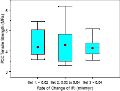
Figure 56 shows the distribution of split tensile strength of PCC for the nondoweled data sets. The median PCC split tensile strength for data sets 1, 2, and 3 were 4.19, 4.30, and 4.14 megapascals (MPa) (608, 624, and 600 poundforce per square inch (psi)), respectively.
Figure 56. Distribution of PCC split tensile strength for nondoweled pavements.
1 MPa = 145.04 psi
1 m/km = 63.4 inches/mi
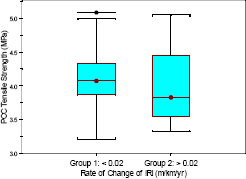
Figure 57 shows the distribution of split tensile strength for doweled sections. The median split tensile strength for data groups 1 and 2 were 4.07 and 3.83 MPa (590 and 555 psi), respectively. The values for group 1 had a tighter distribution around the median compared to group 2. In group 1, 22 percent of the sections had a tensile strength of less than 3.8 MPa (551 psi), while this number was 50 percent for group 2.
The split tensile strength of concrete is directly related to the flexural strength of concrete; higher split tensile strength values are associated with higher flexural strengths. Overall, for both nondoweled and doweled pavements, better pavement performance from a roughness point of view was seen for the sections having a higher split tensile strength.
Figure 57. Distribution of PCC split tensile strength for doweled pavements.
1 m/km = 63.4 inches/mi
1 MPa = 145.04 psi
Elastic Modulus
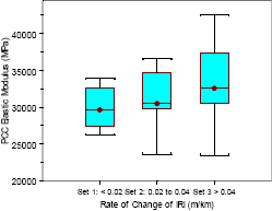
Figure 58 shows the distribution of PCC elastic modulus for the nondoweled data sets. The median PCC elastic modulus for data sets 1, 2, and 3 were 29,627, 30,488, and 32,555 MPa (4.29, 4.42, and 4.72 million psi), respectively. The box plot shows that high PCC moduli values are associated with higher rates of change of IRI.
Figure 58. Distribution of PCC elastic modulus for nondoweled pavements.
1 m/km = 63.4 inches/mi
1 MPa = 145.04 psi
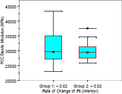
Figure 59 shows the distribution of PCC elastic modulus for the doweled pavements. The median PCC modulus for groups 1 and 2 were 29,627 and 29,455 MPa (4.29 and 4.27 million psi), respectively. The relationship between the roughness progression rate and elastic modulus for the doweled pavements seems to be opposite from the relationship for nondoweled pavements. The pavements with lower rates of change of IRI had higher PCC moduli values.
Figure 59. Distribution of PCC elastic modulus for doweled pavements.
1 m/km = 63.4 inches/mi
1 MPa = 145.04 psi
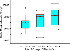
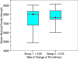
The ratio between the elastic modulus and the split tensile strength of concrete is an indicator of the brittleness of concrete. High values of this ratio indicate a more brittle mix. Figures 60 and 61 show the distribution of this ratio for the nondoweled and the doweled data sets. The median of this ratio for the nondoweled data sets 1, 2, and 3 was 6,989, 8,024, and 8,172, respectively. The median of this ratio for the doweled sections in groups 1 and 2 was 8,002 and 7,649, respectively.
When the range of the ratios above the median was evaluated, it was observed that the range for the nondoweled data set 3 was much higher than that for all other data sets in both the nondoweled and doweled data sets. The numbers indicate that sections with very high values for the ratio between elastic modulus and split tensile strength are associated with poor pavement performance.
Figure 60. Distribution of ratio between PCC elastic modulus and split tensile strength for nondoweled pavements.
1 m/km = 63.4 inches/mi
1 MPa = 145.04 psi
Figure 61. Distribution of the ratio between PCC elastic modulus and split tensile strength for doweled pavements.
1 m/km = 63.4 inches/mi
1 MPa = 145.04 psi
Compressive Strength
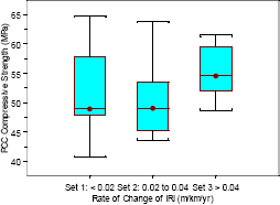
The distribution of PCC compressive strength for the nondoweled data sets is shown in figure 62. The median PCC compressive strength for data sets 1, 2, and 3 were 49, 49, and 55 MPa (7,105, 7,105, and 7,975 psi), respectively. When evaluating both the median and the range of values, it was noted that data set 3 had higher compressive strengths than the other two data sets. Higher cement contents are used for mixes in the freezing regions. It was seen earlier in this report that the pavement sections in data set 3 usually had high freezing indices. Therefore, the higher compressive strength seen for data set 3 is related to these sections being in freezing regions, and thus had higher cement contents that resulted in higher compressive strengths.
Figure 62. Distribution of compressive strength for nondoweled pavements.
1 m/km = 63.4 inches/mi
1 MPa = 145.04 psi
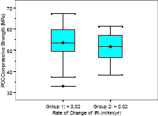
Figure 63 shows the distribution of PCC compressive strength for doweled sections. The median PCC compressive strength for groups 1 and 2 was 54 and 52 MPa (7,830 and 7,540 psi), respectively. No relationship between the compressive strength and rate of increase of roughness can be seen.
Figure 63. Distribution of compressive strength for doweled pavements.
1 m/km = 63.4 inches/mi
1 MPa = 145.04 psi
Concrete Mix Design Parameters
Concrete mix design parameters such as the weight of cement, fine aggregate, coarse aggregate, and the ratio between coarse and fine aggregate in the mix were examined separately for nondoweled and doweled sections to investigate whether differences between the data sets in each pavement type could be observed.
Generally, the amount of cement in the concrete mix in the freezing regions was higher than that in the nonfreezing regions. No differences between the data sets in either nondoweled or doweled sections related to the weight of any mix component could be found.
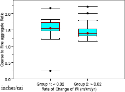
For nondoweled sections, the ratio between coarse and fine aggregate (by weight) had a very wide range: from 0.43 to 2.01. No distinct differences in this ratio between the three data sets in the nondoweled pavements could be observed. The distribution of the coarse-to-fine aggregate ratio for doweled sections is shown in figure 64. The median of this ratio for groups 1 and 2 was 1.55 and 1.40, respectively. These data indicate that generally the coarse-to-fine aggregate ratio for group 1 pavements is higher than that for group 2 pavements.
An evaluation of pavement sections that fell into data set 3 was performed to identify the factors that contributed to the high rate of increase of roughness.
Figure 64. Distribution of coarse-to-fine aggregate ratio for doweled pavements.
1 m/km = 63.4 inches/mi
Eleven nondoweled sections had a rate of change of IRI greater than 0.04 m/km/yr (2.54 inches/mi/yr) (i.e., data set 3). These sections are shown in table 19. The IRI at the first and last profile dates, the change in IRI between these two dates, CI at first and last profile dates, and the total faulting at the section from the distress survey performed closest to the last profile date are also shown in this table. If a fault measurement is not available within 3 years of the last profile date, the faulting at the site is indicated as being not available in this table.
All nondoweled data set 3 sections had a total faulting greater than 60 mm (2.4 inches). Most of these sections also had large changes in CI between the first and the last profile dates. A brief description of each section is set out below.
Section 203060
This section is located in Kansas, was constructed in 1984, and has a 4.6-m (15-ft) joint spacing. The first and last profile years were 1990 and 2002, respectively. During this period, the IRI increased from 1.11 to 1.88 m/km (70 to 119 inches/mi). The pavement structure consists of a 250-mm (9.8-inch) PCC slab placed on an 86-mm (3.4-inch) cement-treated base. The compressive strength and the tensile strength of the PCC were 49 and 3.56 MPa (7,105 and 516 psi), respectively. The elastic modulus of the PCC was 29,110 MPa (4.22 million psi). The total faulting increased from 34 to 83 mm (1.3 to 3.3 inches) from 1994 to 2001. The average faulting at each joint increased from 1 to 2.5 mm (0.04 to 0.10 inches). There was a slight downward curvature in the PCC slabs at the first profile date, and the magnitude of the curvature had increased at the last profile date. This is the only nondoweled section in data set 3 showing a negative curvature at the first and last profile dates.
| GPS Section Number | State or Province | IRI(m/km) | CI x 1,000 (1/m) | Total Faulting (mm inches) | |||
|---|---|---|---|---|---|---|---|
| First Profile Date | Last Profile Date | Change | First Profile Date | Last Profile Date | |||
| 203060 | Kansas | 1.11 | 1.88 | 0.77 | -0.083 | -0.358 | 83 (3.3) |
| 313018 | Nebraska | 1.29 | 2.27 | 0.98 | 0.005 | 0.825 | 158 (6.2) |
| 313033 | Nebraska | 0.83 | 1.95 | 1.12 | 0.036 | 0.767 | 122 (4.8) |
| 323010 | Nevada | 2.23 | 3.02 | 0.79 | 0.304 | 0.188 | 153 (6.0) |
| 323013 | Nevada | 1.76 | 2.17 | 0.42 | 0.178 | 0.249 | N/A |
| 383005 | North Dakota | 1.35 | 1.85 | 0.50 | 0.358 | 1.187 | 61 (2.4) |
| 463010 | South Dakota | 2.06 | 2.52 | 0.46 | 0.572 | 1.035 | N/A |
| 493011 | Utah | 1.32 | 2.66 | 1.34 | 0.094 | 1.383 | 105 (4.1) |
| 553015 | Wisconsin | 1.96 | 2.89 | 0.93 | 0.526 | 0.574 | N/A |
| 563027 | Wyoming | 2.24 | 4.20 | 1.95 | 0.508 | 0.889 | 312 (12.3) |
| 833802 | Manitoba | 1.83 | 4.22 | 2.39 | 0.287 | 0.822 | 102 (4.0) |
| N/A: Not available | |||||||
1 m/km = 63.4 inches/mi
1/m = 1/3.28 ft
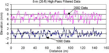
Figure 65 shows the high-pass filtered left wheel path profile plots for this section in 1990 and 2002. An increase in downward curvature is seen for the 2002 data. The last distress survey conducted in 2001 indicated that apart from faulting the only other distress present was 0.7 m (2.3 ft) of longitudinal spalling. The increase in IRI at this section is attributed to the increase in downward curvature and faulting.
Figure 65. Profile data from 1990 and 2002-section 203060.
1 m = 3.28 ft
1 mm = 0.039 inch
Section 313018
This section is located in Nebraska, was constructed in 1985, and has a 4.7-m (15-ft) joint spacing. The first and last profile years for this section were 1990 and 2001, respectively. During this period, the IRI increased from 1.29 to 2.27 m/km (82 to 144 inches/mi). The pavement structure consists of a 302-mm (11.9-inch) PCC slab placed on a 142-mm (5.6-inch) cement-treated base. Values for elastic modulus, compressive strength, and tensile strength of the PCC are not available for this section. The total faulting obtained from the 2002 distress survey was 158 mm (6.2 inches), with an average faulting of 4.9 mm (0.2 inch) at each joint. The distress survey conducted in 2002 showed no other distresses.
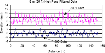
Figure 66 shows the high-pass filtered left wheel path profile plots for this section in 1990 and 2001. The PCC slabs showed very little curvature at the first profile date. However, a significant amount of upward curvature was noted in the PCC slabs at the last profile date. An evaluation of the time-sequence data indicated a trend of increasing curvature over time. The increase in roughness at this section is attributed to the increase in upward curvature and faulting.
Figure 66. Profile data from 1990 and 2001-section 313018.
1 m = 3.28 ft
1 mm = 0.039 inch
Section 313033
This section is located in Nebraska, was constructed in 1986, and has a 4.7-m (15-ft) joint spacing. The first and last profile years were 1989 and 2002, respectively. During this period, the IRI increased from 0.83 to 1.95 m/km (53 to 124 inches/mi). The pavement structure consists of a 236-mm (9.3-inch) PCC slab placed on a 117-mm (4.6-inch) asphalt-treated base. Values for elastic modulus, compressive strength, and tensile strength of the PCC are not available for this section. The total faulting at this section from the 1999 distress survey was 122 mm (4.8 inches), with an average faulting of 3.8 mm (0.15 inch) at each joint. The distress survey performed in 1999 indicated that the other distresses present at this section were two transverse cracks, a 1-m (0.3-ft) length of longitudinal cracking, and 1.1-m (3.6-ft) length of pumping.
The PCC slabs had very little curvature at the first profile date and a significant amount of curvature at the last profile date. The increase in curvature noted at this section was similar to that observed at section 313018, also located in Nebraska. An evaluation of the time-sequence data indicated a trend of increasing curvature over time. The increase in roughness at this section is attributed to the increase in curvature and faulting.
Section 323010
The section is located in Nevada, was constructed in 1982, and has a 4.7-m (15-ft) joint spacing. The first and last profile years were 1989 and 1999, respectively. During this period, IRI increased from 2.23 to 3.02 m/km (141 to 191 inches/mi). The pavement structure consists of a 246-mm (9.7-inch) PCC slab placed on a 142-mm (5.6-inch) cement-treated base. The elastic modulus of the PCC was 23,426 MPa (3.39 million psi), while the tensile strength of the PCC was 4.08 MPa (592 psi). The PCC compressive strength is not available for this section. The distress survey conducted in 2000 indicated that the total faulting at this site was 153 mm (6 inches), with an average faulting of 4.8 mm (0.2 inch) at each joint. The distress survey conducted in 2000 showed numerous distresses at this section. The slabs had a slight upward curvature at both the first and last profile dates; the amount of curvature at the last profile date was slightly less than that obtained at the first profile date. The high roughness at this section is attributed to the high faulting and other distress present at this section.
Section 323013
The section is located in Nevada, was constructed in 1981, and has a 4.7-m (15-ft) joint spacing. The first and last profile years were 1989 and 1998, respectively. During this period, the IRI increased from 1.76 to 2.17 m/km (112 to 138 inches/mi). The pavement structure consists of a 211-mm (8.3-inch) PCC slab placed on a 91-mm (3.6-inch) cement-treated base. The compressive strength and the tensile strength of the PCC were 60 and 3.84 MPa (8,700 and 557 psi), respectively. The elastic modulus of the PCC was 37,378 MPa (5.42 million psi). The fault measurements available for this section were obtained in 1992, which was 6 years before the last profile date, and the total faulting at that time was 26 mm (1.02 inches). The distress survey performed in 1997 indicated that there was some longitudinal cracking and transverse cracking at this section. A slight increase in PCC slab curvature was noted at the last profile date. The cause for the increase in IRI at this section is not clear from the available data.
Section 383005
The section is located in North Dakota, was constructed in 1985, and has a 4.2-m (13.8-ft) joint spacing. The first and last profile years were 1989 and 1998, respectively. During this period, IRI increased from 1.35 to 1.85 m/km (86 to 117 inches/mi). The pavement structure consists of a 203-mm (8-inch) PCC slab placed on a 51-mm (2-inch) granular base. The compressive strength and the tensile strength of the PCC were 54 and 3.86 MPa (7,830 and 560 psi), respectively. The elastic modulus of the PCC was 32,728 MPa (4.75 million psi). The total faulting at this site obtained from the 1999 distress survey was is 61 mm (2.4 inches), with an average faulting of 1.7 mm (0.07 inch) at each joint. No other distresses were present at this section.
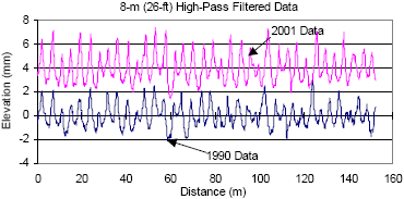
The PCC slabs had an increase in upward curvature between the first and the last profile dates. An evaluation of time-sequence profile data indicated that the curvature was increasing over time. Figure 67 shows the high-pass filtered left wheel path profile plot for the 1989 and 2001 profiles. As seen in the plot, the PCC slabs were curled upwards on both profile dates, with the 2001 data showing a greater magnitude of curvature. The increase in IRI is attributed to the increase in slab curvature and faulting.
Figure 67. Profile data from 1990 and 2001-section 383005.
1 m = 3.28 ft
1 mm = 0.039 inch
Section 463010
The section is located in South Dakota, was constructed in 1983, and has a 4.6-m (15-ft) joint spacing. The first and last profile years were 1989 and 1999. During this period, IRI increased from 2.05 to 2.52 m/km (130 to 160 inches/mi). The pavement structure consists of a 236-mm (9.3-inch) PCC slab placed on a 41-mm (1.6-inch) granular base. The compressive strength and the tensile strength of the PCC were 55 and 4.39 MPa (7,975 and 637 psi), respectively. The elastic modulus of the PCC was 39,962 MPa (5.79 million psi). Faulting data were not available for this section in the database. Distress data at a date close to the last profile date were not available in the database. The PCC slabs showed an increase in upward curvature between the first and the last profile dates. This increase in curvature has contributed to the increase in roughness.
Section 493011
This section is located in Utah, was constructed in 1980, and has a 4.6-m (15-ft) joint spacing. The first and last profile years were 1989 and 2001. During this period, IRI increased from 1.32 to 2.66 m/km (84 to 167 inches/mi). The pavement structure consists of a 259-mm (10-inch) PCC slab placed on a 102-mm (4-inch) cement-treated base. The elastic modulus of the PCC was 30,488 MPa (4.42 million psi); the tensile strength of the PCC was 4.64 MPa (673 psi). The total faulting at this section in 2002 was 105 mm (4.1 inches), with an average faulting of 3.2 mm (0.13 inch) at each joint. The distress survey performed in 2002 indicated that the other distresses at this section were one transverse crack and a transverse spall.
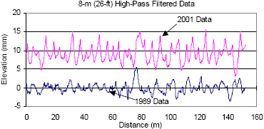
The PCC slabs had a slight upward curvature at the first profile date and a significant upward curvature at the last profile date. Figure 68 shows the high-pass filtered left wheel path profile plots for the 1989 and 2001 data. The significant increase in slab curvature is evident in the plot. An evaluation of the time-sequence profile data indicated that the curvature of the PCC slabs was increasing over time. The increase in IRI is attributed to the increase in slab curvature and faulting.
Figure 68. Profile data from 1989 and 2001-section 493001.
1 m = 3.28 ft
1 mm = 0.039 inch
Section 553015
This section is located in Wisconsin, was constructed in 1984, and has a 4.7-m (15-ft) joint spacing. The first and last profile years were 1990 and 1999, respectively. During this period, the IRI increased from 1.96 to 2.89 m/km (124 to 183 inches/mi). The pavement structure consists of a 244-mm (9.6-inch) PCC slab placed on a 203-mm (8-inch) granular base. The compressive strength and the tensile strength of the PCC were 61 and 4.16 MPa (8,845 and 603 psi), respectively. The elastic modulus of the PCC was 42,546 MPa (6.17 million psi). This section had the highest elastic modulus of the analyzed GPS-3 sections.
The latest faulting data available in the database is from 1992, and the total faulting then was 70 mm (2.8 inches). An evaluation of the profile data collected in 1999 indicated significant faulting. Hence, it appears that the amount of faulting had increased over the years. The distress survey conducted in 1996 indicated that a significant amount of longitudinal spalling was present. The PCC slabs at both profile dates had an upward curvature; however, the magnitude of curvature was virtually the same for the first and the last profile dates. The increase in roughness at this section is attributed to the high faulting.
Section 563027
This section is located in Wyoming, was constructed in 1981, and has a 4.7-m (15-ft) joint spacing. The first and last profile years were 1989 and 2001. During this period, IRI increased from 2.24 to 4.20 m/km (142 to 266 inches/mi). The pavement structure is not available in the database. The compressive strength and the tensile strength of the PCC were 52 and 5.10 MPa (7,540 and 740 psi), respectively. The elastic modulus of the PCC was 31,177 MPa (4.52 million psi). The total faulting at this section in 2001 was 312 mm (12.3 inches), with an average faulting of 9.8 mm (0.4 inch) at each joint. The other distress at this site that was noted during the 2001 distress survey were three transverse cracks, 1.8 m (5.9 ft) of longitudinal spalls, and six transverse spalls having a total length of 1.3 m (4.3 ft). The amount of slab curvature in this section has increased from the first to the last profile dates. The cause for most of the increase in roughness is attributed to faulting, and the increase in slab curvature would have some effect on the increase in IRI.
Section 833802
This section is located in Manitoba, was constructed in 1985, and has a 4.6-m (15-ft) joint spacing. The first and last profile years were 1989 and 2000. During this period, IRI increased from 1.83 to 4.22 m/km (116 to 268 inches/mi). The pavement structure for this section is not available in the database. The compressive strength and the tensile strength of the PCC were 56 and 4.14 MPa (8,120 and 600 psi), respectively. The elastic modulus of the PCC was 32,555 MPa (4.72 million psi). The total faulting at this section observed during the 2000 distress survey was 102 mm (4 inches), with an average faulting of 3.1 mm (0.12 inch) at each joint. A significant amount of transverse spalling is also present at this section. The PCC slabs at this section were curled up during the first and the last profile dates, with the magnitude of the curvature being higher at the last profile date. The increase in roughness is attributed to the high faulting, spalling, and the increase in upward curvature of PCC slabs.
Six doweled sections had a rate of increase of IRI greater than 0.04 m/km/yr (2.54 inches/mi/yr) (i.e., data set 3). These sections are shown in table 20. This table also shows IRI at the first and last profile dates, the change in IRI between these two dates, CI at first and last profile dates, and the total faulting at the section from a distress survey performed closest to the last profile date. Only two doweled sections had a total faulting greater than 25 mm (1 inch). A brief description of each of these sections is provided below.
| GPS Section Number | State or Province | IRI(m/km) | CI x 1,000 (1/m) | Total Faulting ((mm inches)) | |||
|---|---|---|---|---|---|---|---|
| First Profile Date | Last Profile Date | Change | First Profile Date | Last Profile Date | |||
| 123804 | Florida | 1.52 | 2.12 | 0.60 | -0.005 | -0.206 | 109 (4.3) |
| 163017 | Idaho | 1.58 | 2.04 | 0.45 | -0.077 | -0.483 | 25 (1.0) |
| 273003 | Minnesota | 1.94 | 2.64 | 0.69 | -0.876 | -1.642 | 10 (0.4) |
| 283019 | Mississippi | 1.58 | 2.13 | 0.55 | 0.083 | -0.043 | 65 (2.6) |
| 373008 | North Carolina | 1.79 | 2.17 | 0.38 | -0.081 | -0.392 | 5 (0.2) |
| 893015 | Quebec | 1.16 | 3.02 | 1.86 | -0.069 | -0.411 | 7(0.3) |
1/m = 1/3.28 ft
1 m/km = 63.4 inches/mi
Section 123804
The section is located in Florida, was constructed in 1985, and has a 5.9-m (19-ft) joint spacing. The first and last profile years were 1990 and 2000, respectively. During this period, IRI increased from 1.52 to 2.12 m/km (96 to 134 inches/mi). The pavement structure consists of a 305-mm (12-inch) PCC slab placed on a 170-mm (6.7-inch) cement-treated base. The compressive strength and the tensile strength of the PCC were 42 and 3.54 MPa (6,090 and 513 psi), respectively. The elastic modulus of the PCC was 27,216 MPa (3.94 million psi).
This pavement had the highest faulting of the doweled sections analyzed in this study. This was the only doweled section in which faulting was recorded at the cracks. The total faulting obtained from the 2002 distress survey was 109 mm (4.3 inches), with a total faulting at joints and cracks of 65 and 44 mm (2.6 and 1.7 inches), respectively. A slight increase in downward curvature is seen between the first and the last profile dates. The high increase in roughness is attributed to the faulting. This section had the fourth highest cumulative traffic of the analyzed doweled section.
Section 163017
The section is located in Idaho, was constructed in 1986, and has a 4.4-m (14-ft) joint spacing. The first and last profile years were 1989 and 2001, respectively. During this period, IRI increased from 1.58 to 2.04 m/km (100 to 129 inches/mi). The pavement structure consists of a 262-mm (10.3-inch) PCC slab placed on a 137-mm (5.4-inch) cement-treated base. The elastic modulus of the PCC was 31,350 MPa (4.54 million psi) and the tensile strength of the PCC was 3.73 MPa (544 psi). The compressive strength of the PCC is not available. The total faulting at this site from the 1999 distress survey was 25 mm (1 inch), with an average faulting of 0.7 mm (0.03 inches) at each joint. The only other distress recorded during the 2002 survey was longitudinal cracking.
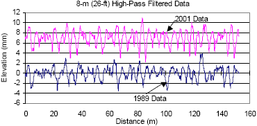
The downward curvature of the concrete slabs increased significantly between the first and last profile dates. Figure 69 shows the high-pass filtered left wheel path profile plots for 1989 and 2001. The plots show a clear increase in downward curvature of the PCC slabs between the years. An evaluation of the monitored data indicated that the downward curvature had increased over time. The increase in downward curvature of the slabs contributed to the increase in roughness.
Figure 69. Profile data from 1989 and 2001-section 163017
1 m = 3.28 ft
1 mm = 0.039 inch
Section 273003
The section is located in Minnesota, was constructed in 1986, and has a 4.6-m (15-ft) joint spacing. The first and last profile years were 1990 and 2001, respectively. During this period, IRI increased from 1.94 to 2.64 m/km (123 to 167 inches/mi). The pavement structure consists of a 193-mm (7.6-inch) PCC slab placed on a 127-mm (5-inch) granular base. The compressive strength and the tensile strength of the PCC were 55 and 3.78 MPa (798 and 548 psi), respectively. The elastic modulus of the PCC was 34,450 MPa (5 million psi). The total faulting obtained from the 1999 distress survey was 10 mm (0.4 inch), which is a very low value. The only other distress noted during the 2002 survey was four transverse spalls.
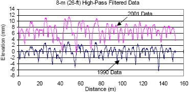
Figure 70 shows the high-pass filtered left wheel path profile plots for 1990 and 2001. The section had a significant downward curvature at the first profile date, and the plot shows the downward curvature has increased from 1990 to 2001. The CI at the last profile date was the highest for all doweled sections. An evaluation of the time-sequence profile data indicated that the downward curvature of the slabs had increased over time. The increase in roughness is attributed to the increase in downward curvature of the PCC slabs.
Figure 70. Profile data from 1990 and 2001-section 273003.
1 m = 3.28 ft
1 mm = 0.039 inch
Section 283019
The section is located in Mississippi, was constructed in 1984, and has a 6.1-m (20-ft) joint spacing. The first and last profile years were 1990 and 2001, respectively. During this period, IRI increased from 1.58 to 2.13 m/km (100 to 135 inches/mi). The pavement structure consists of a 239-mm (9.4-inch) PCC slab placed on a 150-mm (6-inch) cement-treated base.
The compressive strength and the tensile strength of the PCC were 52 and 4.80 MPa (7,540 and 696 psi), respectively. The elastic modulus of the PCC was 28,776 MPa (4.17 million psi). The total faulting at this site during the 2000 distress survey was 65 mm (2.6 inches), with an average faulting of 2.7 mm (0.10 inch) at each joint. This section had the second highest faulting of all doweled sections. Numerous other distresses were noted at this section, including longitudinal cracking and spalling. This section had a slight upward curvature at the first profile date and a slight downward curvature at the last profile date. The faulting and other distresses are attributed to the increase in roughness.
Section 373008
The section is located in North Carolina, was constructed in 1984, and has a 6.5-m (21-ft) joint spacing. The first and last profile years were 1990 and 2001, respectively. During this period, IRI increased from 1.79 to 2.17 m/km (113 to 138 inches/mi). The pavement structure consists of a 239-mm (9.4-inch) PCC slab placed on a 150-mm (6-inch) cement-treated base. The compressive strength and the tensile strength of the PCC were 52 and 4.80 MPa (7,540 and 696 psi), respectively. The elastic modulus of PCC was 28,776 MPa (4.17 million psi). The 2002 distress survey indicated the total faulting at this site to be a negligible 5 mm (0.2 inch). The 2002 distress survey indicated a significant amount of longitudinal cracking. There was a slight downward curvature in the PCC slabs at the first profile date, and the magnitude of the curvature had increased at the last profile date. The high amount of cracking is the most likely cause for the increase in roughness.
Section 893015
The section is located in Quebec, was constructed in 1984, and has a 6-m (20-ft) joint spacing. The first and last profile years were 1989 and 1999, respectively. During this period, IRI increased from 1.16 to 3.02 m/km (74 to 191 inches/mi). The pavement structure consists of a 208-mm (8.2-inch) PCC slab placed on a 338-mm (13.3-inch) gravel base. The compressive strength and the tensile strength of the PCC were 42 and 3.32 MPa (6,090 and 481 psi), respectively. The elastic modulus of the PCC was 29,627 MPa (4.29 million psi). The total faulting at this site during the 2000 distress survey was 7 mm (0.28 inch).
There was a slight downward curvature in the PCC slabs at the first profile date, and the magnitude of the curvature had increased at the last profile date. The PCC tensile strength is the third lowest of all doweled sections. A significant amount of transverse spalling was observed, along with numerous patches and other distresses during the last distress survey performed at this section. The downward curvature of the slabs would have increased the potential for transverse cracking. The various distresses on this site appear to be the cause for the high roughness.
Most of the nondoweled sections that were showing a high rate of increase of roughness had high faulting and high CI values. The PCC slabs were curled upwards in all sections except for one. An evaluation of the time-sequence profile data of these sections showed that the amount of slab curvature increased over time at most of these sections. The excessive slab curling at these sections would have been a contributing factor that caused high faulting to occur at these sections. When the slabs are curled upward, there is a potential for water to accumulate at the joints, and because the slabs will deflect as traffic passes, the potential for faulting is high.
For the doweled pavements that showed a high rate of increase of roughness, there were a few cases where the slabs showed an excessive amount of downward curvature. The potential for midslab cracking is high when a PCC slab takes such a shape. This slab shape would have been a contributing factor in causing pavement distress at these sections.