U.S. Department of Transportation
Federal Highway Administration
1200 New Jersey Avenue, SE
Washington, DC 20590
202-366-4000
Federal Highway Administration Research and Technology
Coordinating, Developing, and Delivering Highway Transportation Innovations
 |
||
 | report |  |
| This report is an archived publication and may contain dated technical, contact, and link information | ||
| Federal Highway Administration > Publications > Research > Infrastructure > Structures > Geosynthetic Reinforced Soil Integrated Bridge System Interim Implementation Guide |
Publication Number: FHWA-HRT-11-026
Date: January 2011 |
Geosynthetic Reinforced Soil Integrated Bridge System Interim Implementation GuideCHAPTER 5. SPECIAL REQUIREMENTS FOR HYDRAULIC AND SEISMIC CONDITIONS5.1 INTRODUCTIONThis chapter describes how extreme events such as scour, seismicity, or impact may alter the design of GRS–IBS.
5.2 HYDRAULIC DESIGNWhen bridges are constructed to span a waterway, their foundations must be designed, detailed, and constructed in compliance with section 2.6 (Hydrology and Hydraulics) of the AASHTO LRFD Bridge Design Specifications or an FHWA Division Office–approved drainage or bridge manual.( 9 ) These provisions apply equally to both shallow and deep foundations. GRS–IBS has been successfully used to build abutments near rivers and streams. However, assessing the potential impact of stream instability, scour, and adverse flow conditions is a vital consideration in the decision to use this technology. The potential for issues with stream instability, scour, and adverse flow conditions can lead to deep foundation bottom elevations or expensive countermeasures that could reduce the cost–effectiveness of GRS–IBS abutments. If the potential for abutment scour, contraction scour, long–term degradation, or channel migration is high, costly design considerations or countermeasures could be required. Other factors, such as channel instability and adverse flow conditions (skewed approach flow, highly contracted flow, high velocity flow through the bridge opening, etc.) at the bridge, could also result in costly design considerations or countermeasures to stabilize the channel against further instability. Any of these conditions might make it advisable to select an alternative bridge abutment technology. A thorough hydraulic analysis, scour evaluation, and assessment of channel stability of a bridge design will include an appropriate estimate of the design flow, development of water surface profiles through the proposed opening, assessment of scour (abutment, contraction, and long–term degradation), and if necessary, the design of countermeasures to protect the bridge or stabilize the channel. FHWA and others have developed procedures to assist the engineer in performing these analyses, and these procedures should be followed for GRS–IBS design.( 5, 14, 15 )
5.3 HYDRAULIC DESIGN CONSIDERATIONSThere are a number of important factors to consider when completing a thorough hydraulic design and scour evaluation of a bridge. The determination of a scour elevation based on the computed scour depth; the selection, design and installation of a scour countermeasure; and postconstruction inspection are important factors that must be adequately addressed. The following factors should be considered:
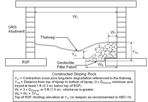
Figure 36 Illustration. Typical cross section for sloping rock (adapted).( 5 )
Another hydraulic consideration is drainage. The potential for unbalanced water pressure exists when a wall can become partially submerged by a flood or when surface drainage is not controlled. All GRS structures should include consideration for surface and subsurface drainage. Critical areas are behind the wall at the interface between the GRS mass and the retained fill, at the base of the wall, and any location where a fill slope meets the wall face. For example, the design needs to include provisions for surface drainage along the fill slope adjacent to the wing walls. Section
5.4 SEISMIC DESIGNExternal stability for seismic design will need to be checked for GRS–IBS just like with any other gravity structure. Design considerations for external stability and seismicity include increasing the base width of the wall and increasing the length of the reinforcement at the top of the wall. Additional bearing capacity and overall external stability is generally improved by increasing the base width of the wall. Additional stability is created by increasing the length of the reinforcement at the top of the wall or abutment. This integrated approach has also been shown to be beneficial because it keys the structure into the existing terrain, preventing the development of a failure plane along the cut slope, which can lead to progressive failure. No seismic design requirements are necessary for the internal stability of GRS–IBS. Reinforced soil walls have been known to perform better than conventional retaining walls under seismic loading, as evidenced by observations of actual performance in strong earthquake events. (See references 16–19.) A National Cooperative Highway Research Program (NCHRP) study is being conducted to establish guidelines for the design and construction of GRS abutments under seismic loading.( 20 ) As part of the NCHRP study, a 12–ft–high GRS abutment supporting a bridge load of about 1,000 kipswas subject to sinusoidal motions on a shake table. No significant damage or movement was recorded until the acceleration was increased to 1.0 g, at which time base sliding between the GRS abutment and foundation soil became apparent. The superstructure would not have failed due to the deformation of the GRS mass at the 1.0–g acceleration. This experiment suggests that a GRS abutment is capable of withstanding at least low to medium earthquakes without any special provisions.
5.5 IMPACT EVENTSThere is limited information on vehicle impact against GRS–IBS. Typically, GRS walls along roadways are built behind a crash barrier. A niche function of GRS technology, however, is rock–fall protection. That application is not covered in this manual, but it serves to show that GRS is capable of withstanding considerable lateral and vertical impacts without failure or loss of serviceability.
|