U.S. Department of Transportation
Federal Highway Administration
1200 New Jersey Avenue, SE
Washington, DC 20590
202-366-4000
Federal Highway Administration Research and Technology
Coordinating, Developing, and Delivering Highway Transportation Innovations
 |
||
 | report |  |
| This report is an archived publication and may contain dated technical, contact, and link information | ||
|
Publication Number: FHWA-HRT-11-026
Date: January 2011 |
Geosynthetic Reinforced Soil Integrated Bridge System Interim Implementation GuideCHAPTER 6. IN–SERVICE PERFORMANCE6.1 INTRODUCTIONThis chapter presents methods of evaluating the performance of GRS–IBS, including deformations, thermal movements, and scour monitoring. The performance of in–service GRS–IBS structures can be found in the synthesis report.( 1 ) A distinctive feature in the design of GRS-IBS is that it works with settlement instead of resisting it to create a compatible connection between the approach and the road, providing a long–term solution to the bump at the end of the bridge. Reducing the bump at the end of bridge will improve the overall performance and serviceability of the bridge. This bump not only creates a chronic maintenance issue but also induces an amplification of LL on the superstructure, creating fatigue on bridge elements. Recently, some owners have shifted their focus on the combined effects of corrosion and fatigue in the evaluation of a bridge's health. The design objective of IBS addresses these two critical durabilityissues by attempting to create a smooth, jointless, affordable bridge system. GRS–IBS was developed to meet the demand for the next generation of small, single span bridges in the United States as part of the FHWA's Bridge of the Future initiative and is built without many of the standard abutment components associated with a traditional bridge (e.g., approach slab, sleeper slab, traditional bridge bearings, joint details). The performance of the first series of GRS–IBS indicates that this method has considerable potential to advance the state of the practice.
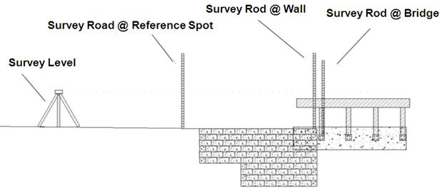
6.2 DEFORMATIONSThe performance of nearly 20 bridges built with GRS–IBS has been an improvement on similar bridges built with conventional construction techniques. The GRS–IBS bridges have performed as well as the conventional bridges structurally and functionally in addition to eliminating the bump at the end of the bridge that often results from conventional construction. The suppression of the bump at the end of the bridge has been maintained for all GRS–IBS bridges that are in service. The first bridge constructed with the IBS method, the Bowman Road Bridge, has been in service since 2005. As of 2010, there has been no development of a crack in the asphalt layer from the road to the bridge. The total settlement and deformation (and thus vertical strain) of the GRS abutment due to bridge load is recorded using either a standard survey level and rod system, as shown in figure 37, or an electronic distance measurement (EDM) survey referenced off a permanent survey pole and benchmarks. The precision of all survey measurements (both the survey level method and the EDM system) is ±0.005 ft.
Figure 37. Illustration. Survey level method for superstructure and wall settlement. Using either settlement measurement technique, the settlement is recorded for both the abutment face wall and the superstructure. The difference between the settlement measured on the abutment face wall and the superstructure is the vertical deformation within the GRS mass alone due to the bridge load. To determine secondary settlement (i.e., creep), plot settlement versus log–time. For surveys where a survey level is used, bridge settlement should be measured at four locations (each corner of the bridge) to check for angular distortion and differential settlement. Wall settlement is recorded by the rod off the top of the CMU facing block adjacent to the superstructure, and superstructure settlement is measured with the rod off a guardrail hanger bolt (see figure 37 ). For surveys with an EDM system, the total station is referenced off of a permanent pole embedded beneath the frost line and within accessible sight to both abutment face walls. Targets placed on the abutment wall face and the bridge beam or footing are then used to measure movement relative to the permanent pole. Figure 38 shows an example of this for the Tiffin River Bridge in Defiance County, OH. Lateral and vertical movement of the abutment wall face was measured using custom reflective survey targets, which are shown in the black circles in figure 38. Movement of the GRS abutment was measured using targets placed on the concrete footing itself, which are shown in the red circles in figure 38. The difference between the two readings (movement of the abutment and movement of the wall face) provides the compression of the GRS abutment alone, not including foundation settlement. Note that the permanent pole should be installed prior to placement of the steel girders on the CIP footings (see figure 39 ).
Figure 38. Photo. Location of survey targets on Tiffin River Bridge , Defiance County , OH .
Figure 39. Photo. Location of total station reference pole.
6.3 THERMAL CYCLESThermal cycles occur on every bridge structure due to sustained temperature variations. The severity of the expansion and contraction depends on the coefficient of thermal expansion of the bridge. However, observations of bridges built in moderate climates indicate considerable compatibility between the superstructure and the integrated approach, resulting in a smooth transition. GRS–IBS accommodates movement through the integrated transition zone behind the beam ends. The road base is wrapped with geotextile and then compacted directly against the beam end. This process is described in detail in chapter 7. The wrapped face confines the soil and allows the beam to contract without the fill behind the beam ends sloughing off to fill the void. Because of this, excess pressures behind the beam during expansion are also avoided. The road base is not only wrapped vertically but also laterally to prevent lateral spread.
6.4 MONITORING FOR SCOURThe riprap protection should be monitored during each bridge inspection or after an extreme flood. Any movement of rock should be noted and replaced to prevent scour from progressing and undermining the RSF or the abutment. In all current installations of GRS abutments, no problems have been reported. It should be noted that these installations have been built in non–scour–critical environments and with appropriate countermeasures, as recommend in current practice.( 5 ) An indicator of scour on an abutment face or wing wall can be achieved by using colored blocks on the bottom five to eight rows of the abutment. Solid blocks are recommended in the bottom rows as they are more likely to resist any impact of moving riprap, ice, or other abrasion associated with the normal water elevation. The solid colored blocks are also covered from view by the riprap. Any exposure of colored blocks could indicate movement or undermining of the riprap, requiring inspection and possibly remediation or repair to protect the RSF and abutment from scour.
|