Post-Earthquake Reconnaissance Report on Transportation Infrastructure: Impact of the February 27, 2010, Offshore Maule Earthquake in Chile
CHAPTER 6. LESSONS LEARNED FROM THE EARTHQUAKE
6.1 GENERAL
This chapter summarizes the overall performance of various bridge components, retaining walls, and bridge sites based on the observations detailed in chapter 4 and chapter 5. The observed performance leads to various lessons learned from the 2010 offshore Maule earthquake. It
forms the basis for several conclusions drawn from the postearthquake reconnaissance regarding recommended seismic design and retrofit improvements and future research needs.
6.2 SUPERSTRUCTURE ROTATION
6.2.1 Skewed Bridges
The direction of bridge skew is illustrated in figure 278 for clarity in the following discussions. Skew is defined as the direction of rotation from the transverse line (perpendicular to the bridge centerline) to the skew side or abutment back wall of the bridge. For example, figure 278 indicates a clockwise skew and a counterclockwise skew.
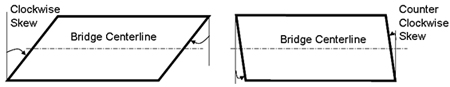
Figure 278. Illustration. Notations on skew direction.
Table 7 summarizes the characteristics and earthquake-induced damage patterns of bridges with a skew angle of 20 degrees or more. It lists the bridge name, bridge orientation, skew angle, skew direction, material used in girder, presence of diaphragms, transverse displacement at intermediate bents, and direction of deck rotation. The combination of these parameters helps determine the mechanism of bridge deck rotations.
Table 7. Summary of bridges and bridge damage.
Bridge Characteristics |
Damage Pattern |
Site |
Name |
Orientation |
Skew and
Direction |
Girder/End
Diaphragm |
Transverse Movement at Intermediate Bents |
Rotation |
1a
1b |
Miraflores |
NE-SW |
20 degrees
counterclockwise |
Concrete/No |
Negligible |
Clockwise |
2a |
Lo Echevers |
NE-SW |
33 degrees counterclockwise |
Concrete/No |
Negligible |
Clockwise |
5 |
Quilicura |
E-W |
45 degrees counterclockwise |
Steel/Yes |
Negligible |
Clockwise |
7 |
Romero |
E-W |
31 degrees clockwise |
Concrete/No |
Negligible |
Counterclockwise |
10b |
Hospital |
NW-SE |
40 degrees counterclockwise |
Concrete/No |
Significant |
Clockwise |
All of the bridges in table 7 consistently rotated about the centroid of the bridge superstructure in the opposite direction of their skew, regardless of the bridge orientation, magnitude of the skew angle, or presence of diaphragms. The fact that most of the bridges experienced negligible transverse displacements also indicates that the rotation effect was dominant in these bridge superstructures, with the acute corners of each bridge moving away from their abutments at both ends.
Based on the observations, the movement of a bridge superstructure can be illustrated in four steps, as shown in figure 279. Under the earthquake excitations (steps 1a, 1b, and possibly 3), the bridge superstructures first moved toward one abutment (left in figure 279) and impacted against the abutment back wall (step 2). The reaction from the back wall then turned the superstructure in a direction opposite to the skew direction (counterclockwise in figure 279). The rotational motion (step 3) was amplified due to the fact that the rotational vibration mode of the bridge superstructure is more sensitive to the ground motions, as illustrated with the acceleration response spectra recorded at Hospital Station in Curicó, since all the concrete girder bridges listed in table 7 have superstructures supported on neoprene pads and restrained with vertical seismic bars (see figure 280).(6) The superstructures are weakly restrained in plan with the fundamental vibration mode in translation. With continuing deck rotations, the acute corners at two ends of the bridge finally moved away from the abutments, knocking off the curtain walls and becoming unseated (steps 4a and 4b). Note that the possibility of having significant rotational ground motions at the bridge site can further amplify the rotational motion (step 3).
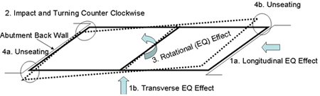
Figure 279. Illustration. Deck rotation of a representative bridge (two spans shown).
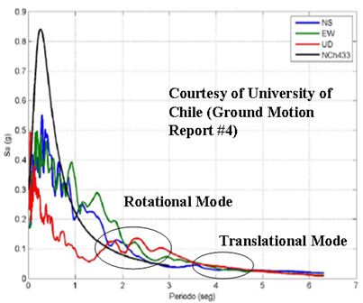
Figure 280. Illustration. Rotational and translational mode responses to ground motions.
6.2.2 Straight Bridges
The bridges with little or no skew (Chada and Las Mercedes bridges) rotated counterclockwise, as discussed in chapter 4. Unlike the skewed bridges, the deck rotation of the straight bridges cannot be explained by the skew effect. The possible factors contributing to significant rotations in these bridges are as follows:
- The rotational mode of vibration of those bridges was very sensitive to ground motions. Any accidental eccentricity between the center of mass and the center of rigidity of the superstructure of a bridge could lead to substantial rotations.
- The rotational component of ground motions could be significant.
- The fault directivity effect could be significant because both bridges are approximately oriented along the east-west direction.
Considering both the skewed and straight bridges, observations can be made on the overall reasons for bridge deck rotation. Skew of bridges is a significant but not necessarily decisive factor contributing to the bridge rotation. The high sensitivity of the rotational vibration mode of the bridge to ground motion, particularly rotational excitations, could have been dominant. The fact that all bridges experiencing significant rotations were not far from Santiago, where soil conditions are relatively stiff, supports the possibility of rotational ground motions at the bridge sites. Further analysis is required to understand the significance of this phenomenon.
6.3 GIRDER DAMAGE
6.3.1 Fracture of Steel Girders
The superstructure of the Cardenal Raúl Silva Henríquez bridge is divided into two parts by the center expansion joints at bent 11. The northeast portion of the bridge is supported by a concrete substructure, and the southwest portion is mainly supported on a steel substructure. Most of the bridge bents are supported on drilled shafts. During the earthquake, the two parts most likely vibrated separately.
The most plausible reason for the girder damage at each abutment, as discussed in chapter 4, is excessive longitudinal force applied on the end support. During the earthquake, the majority of the inertia force on half of the bridge superstructure was resisted by the end support at each abutment. The excessive force resulted in either fillet weld fractures at the southwest abutment or steel girder fractures in web and bottom flange at the northeast abutment.
6.3.2 Failure of Concrete Girders
The exterior prestressed concrete girders of the Chada and Romero bridges, which were constructed without diaphragms, experienced out-of-plane block shear failures due to transverse impact loads from shear keys, as shown in figure 281. When partial diaphragms were used between the girders, such as in the San Nicolás bridge, the bottom portion of the exterior girder still experienced significant shear cracking, as shown in figure 282. However, with the use of even partial concrete teeth between girders, as shown in the Llacolen bridge in figure 283, both exterior and interior prestressed concrete girders suffered no visible damage. One interior girder in the west portion of Llacolen bridge experienced a horizontal crack, as shown in figure 57. This was because the concrete teeth provided sufficient lateral restraints on most of the girders, making them work together and share the transverse seismic force.
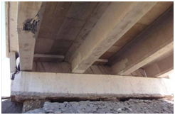
Figure 281. Photo. Exterior girder damage at Chada bridge, no diaphragms.
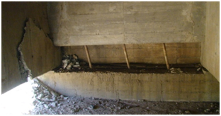
Figure 282. Photo. Exterior girder damage at San Nicolás bridge, partial diaphragms.
Figure 283. Photo. Exterior girder damage at west abutment of Llacolen bridge, concrete teeth.
6.4 CONNECTION BETWEEN SUPERSTRUCTURE AND SUBSTRUCTURE
6.4.1 Shear Key and Steel Stopper Failures
Concrete shear keys or shear keys in integral construction with curtain walls fulfilled the function of sacrificial devices to protect the substructure of bridges. Their failures were observed regardless of the presence of bridge deck rotations during the earthquake (e.g., Independencia, Chada, Romero, and Hospital bridges).
Steel stoppers used in several bridges (e.g., Independencia, Miraflores, and Lo Echevers bridges) failed prematurely. The Independencia bridge with steel stoppers was taken out of service following the earthquake, but the parallel bridge with concrete shear keys and diaphragms survived the earthquake with repairable damage. It was concluded that the two-bolt connections from each steel stopper to the cap beam was too weak to resist any significant bending moment. However, once welded to steel girders, the steel stoppers prevented lateral movement of girders, as observed in the Quilicura railway bridge shown in figure 112.
6.4.2 Vertical Seismic Bars
Vertical seismic bars were used in a number of bridges (e.g., Chada, Las Mercedes, Llacolen, Romero, Hospital, and Pichibudis bridges). In general, they were flexible and underwent significant deformations during the earthquake. All were well anchored into the cap beams and decks. Field evidence only indicated bar pullout in bridges with fallen spans. It is uncertain whether the seismic bars provided vertical restraints to the bridge girders because there was no evidence of vertical up-and-down movements of the girders. This observation may be clarified after analyses using recorded ground motions.
6.4.3 Bridge Bearings
In general, bridge bearings functioned well during the earthquake. Several of them were displaced significantly, such as in the Lo Echevers bridge shown in figure 95 and in the Cardenal Raúl Silva Henríquez bridge shown in figure 125.
6.5 GIRDER SEAT LENGTH
The superstructure of a number of concrete and steel girder bridges (e.g., Llacolen, Miraflores, Lo Echevers, Romero, Hospital, Tubul, Biobío, and pedestrian bridges) dropped off their supports during the earthquake. In general, the support seat length is insufficient.
6.6 COLUMN SHEAR FAILURE
The pier caps and piers in all but the Llacolen and Juan Pablo II bridges received virtually no damage during the earthquake. This represented successful design of these bridge components. Several columns in the Llacolen and Juan Pablo II bridges failed in shear due mainly to the ground settlement and lateral spreading.
6.7 FOUNDATION MOVEMENT AND DAMAGE
6.7.1 Overview
In general, bridge foundations performed relatively well in the earthquake. With the exception of cases where liquefaction-induced vertical or lateral soil movement was severe, foundations did not appear to suffer significant permanent deformations or significant damage, based on surficial observations. Most of the newer bridges visited were supported by shaft foundations (typically 4.9 ft (1.5 m) in diameter and less than 98 ft (30 m) deep). These foundations appeared to be relatively light compared to bridge foundations currently used in areas of high seismic hazard in the United States. However, the foundations performed well in most cases.
To identify lessons learned regarding bridge foundations, two broad categories of geotechnical performance issues must be considered: foundation performance when liquefiable soils were probably not present and foundation performance when liquefiable soils were present. For those sites where liquefaction probably occurred, geotechnical performance issues are further divided between the effects of liquefaction-induced settlement and liquefaction-induced ground failure and the effects of lateral movement. The observations of geotechnical performance of foundations in the sections that follow are made within this context.
6.7.2 Sites Not Affected by Liquefaction
Seventeen of the 32 sites visited did not appear to have significant liquefaction. However, poorer soil conditions (e.g., soft to still clays or loose sands) appeared to contribute to the amplification of ground motions (see chapter 2) and increased foundation deformation (see chapter 5), possibly increasing stress or deformation in the superstructure. In general, sites where better soil conditions were present performed better and showed minimal damage. Near-surface soft to stiff clays appeared to be especially troublesome, especially in terms of their effect on approach fill stability (e.g., sites 7, 8, and 10), but did not cause movement of or damage to the bridge abutments.
6.7.3 Sites Affected by Liquefaction
None of the sites where liquefaction likely occurred (15 of the 32 sites visited) were specifically designed to mitigate the effects of liquefaction through use of ground improvement or foundation strengthening (see chapter 5 for additional background on this issue). This affords the opportunity to observe the effect liquefaction can have on foundation and abutment performance for structures that are otherwise designed using the AASHTO or similar specifications, depending on the age of the structure.
6.7.3.1 Effects of Liquefaction-Induced Ground Failure
What was most surprising was the good performance of bridge abutments retaining 13- to 26-ft (4- to 8-m)-high approach fills over gently sloping ground, even when severe vertical and horizontal approach fill deformation (1.6 to 3 ft (0.5 to1 m) or more) occurred due to liquefaction of soil below the approach fill (see table 6, specifically sites 15, 20, 21, 22, and 27). Although there were a few cases where 1.9 to 5.8 inches (50 to 150 mm) of lateral movement of the abutment appeared to have occurred, in most cases, no discernable movement occurred. This may be the result of three-dimensional effects reducing the lateral forces acting on the abutment foundations relative to what would be predicted assuming two-dimensional (i.e., plane strain) conditions. Furthermore, the liquefaction-induced slope failure tended to follow the path of least resistance (i.e., in the direction perpendicular to the roadway and bridge centerline). For those cases where either the abutment or an interior pier was located on a general slope, such as at a riverbank, the beneficial three-dimensional slope geometry was not present and foundation and substructure movement and damage due to liquefaction-induced ground failure was more likely (e.g., sites 17, 18, 19, and 25; see chapter 5 for details). These observations may have important implications for the strategy used for liquefaction design of bridges both in Chile and the United States.
6.7.3.2 Effects of Liquefaction-Induced Settlement and Downdrag
Liquefaction-induced ground settlement was observed at many of the bridge sites where liquefaction occurred. However, settlement of the bridge foundations only occurred for a few of those sites (sites 25, 27, and 31). In general, regardless of the amount of liquefaction-induced ground settlement that occurred, the foundations did not settle significantly if tipped in a reasonably good bearing layer. However, if the foundation was relatively shallow and not tipped in a relatively dense bearing layer, significant settlement of the foundation did occur.
6.8 RETAINING WALLS AND ROADWAY FILL
Three types of walls were inspected by TIRT: panel-faced MSE walls using bar mat or steel strip soil reinforcement, modular block high-density polyethylene geogrid reinforced walls, and concrete gravity walls. Overall, retaining walls performed well during the earthquake. Tieback and soil nail walls appeared to suffer little or no damage based on observations made by others. True MSE abutments, where the bridge footing foundation was directly supported on top of the MSE wall (e.g., site 11, see chapter 5), also performed well with no apparent deformation or damage to the walls. Note that most of these walls were designed using the AASHTO Standard Specifications (see chapter 3). The observed wall performance appears to indicate that the AASHTO specifications as applied in Chile provide a safe design for seismic loading conditions.
There was no evidence of lateral sliding of the walls, the limit state that often controls wall design for seismic conditions in North American design practice (see chapter 5). Where wall face lateral movement was observed, the movement was primarily rotational, with the maximum movement near the wall top. It appears that the passive resistance at the wall toe in combination with friction along the wall base prevented significant translational movement.
Minor damage observed in several walls was due mainly to poor detailing. Inadequate coping details allowed a few of the top blocks to topple off the wall (modular block walls). Poor wall corner details or vertical full height joint details (such as between the curtain wall and MSE wall retaining the approach fill sides) allowed panels to separate and wall backfill to spill out through the gaps in the facing. Stresses during seismic loading, especially for relatively tall walls (30 ft (9 m) or more) appeared to be more pronounced at abrupt changes in wall geometry (e.g., corners and small radius changes in alignment), indicating the need for more robust wall facing designs in that type of situation. Soil reinforcement that is too short, especially near the wall top or where uniform low shear strength medium sand is used as backfill, can contribute to excessive wall or panel movement.
|


