Post-Earthquake Reconnaissance Report on Transportation Infrastructure: Impact of the February 27, 2010, Offshore Maule Earthquake in Chile
APPENDIX B. SEISMIC DESIGN REQUIREMENTS FOR BRIDGES AND WALLS IN CHILE
B.1 SEISMIC DESIGN REQUIREMENTS FOR BRIDGES
Section 3.1004 of the MOP Highway Handbook establishes the seismic design requirements for small to medium span bridges (viaducts, overheads, and pedestrian bridges) with span lengths less than 230 ft (70 m ).(11) Longer bridges and those with special structural configurations (arches, suspension, and cable-stayed bridges) are not covered by these specifications.
The philosophy underlying these specifications is to ensure public safety, but significant damage and disruption to service is accepted. The ground motions and design forces are calculated based on a probability of exceedance of 10 percent in 50 years, which is equivalent to a return period of 475 years. For design purposes, the country is divided into nine regions from north to south and in three seismic zones from east to west. These zones are determined by the value of the PGA in stiff soil, as shown in table 8. Zonation maps are included in the seismic provisions for all of the nine regions. The map for central Chile is shown in figure 22.
Table 8. Seismic zones.
Seismic Zone |
PGA,
Ao |
Seismic Coefficient |
1 |
0.20 g |
0.20 |
2 |
0.30 g |
0.30 |
3 |
0.40 g |
0.40 |
The effect of the soil stiffness on the values of PGA at a specific site are taken in account by multiplying the values in table 8 by a soil coefficient defined in table 9.
Table 9. Soil coefficients.
Soil Type |
Description |
S |
I |
Rock with measured shear wave velocity, Vs > 2,600 ft/s (800 m/s) |
0.9 |
II |
Very dense soil with measured shear wave velocity, 1,300 ft/s (400 m/s) < Vs < 2,600 ft/s (800 m/s) |
1.0 |
III |
Soft to medium-stiff clays and sands. Unsaturated sands with N > 20 blows/ft |
1.2 |
IV |
Saturated cohesive soils with Su > 0.0036 ksi (0.025 MPa) |
1.3 |
For seismic zones 2 and 3, an importance coefficient is included in the calculation for seismic forces. Bridges are classified as either "essential" (importance coefficient I) or "other" (importance coefficient II).
Since scour around or under a bridge foundation may influence its seismic behavior, the consequences of this hazard are included in the design. Two values of a seismic scour index (PSS) are defined. A value of PSS equal to 1 requires 75 percent of the total depths of scour to be considered in design, and a value of 2 requires 100 percent of the total scour to be considered in design. The depth of scour is included in the determination of the height of the superstructure (substructure slenderness) and consequently affects the appropriate analysis method.
Four categories of seismic behavior are defined based on the PGA, PSS, and the importance coefficient, as shown in table 12.
Table 10. Seismic behavior categories.
PGA, Ao |
PSS |
Importance Coefficient |
I |
II |
0.20 g |
1 |
a |
a |
2 |
b |
b |
0.30 g |
1 |
b |
b |
2 |
c |
c |
0.40 g |
1 |
c |
c |
2 |
d |
d |
B.1.1 Analysis Methods
One of five analysis methods is used in to determine the elastic seismic forces, depending on the geometry and importance of the bridge. These methods are: the seismic coefficient method, the seismic coefficient method modified by structural response, the modal spectral analysis method, the modal spectral analysis method using site-specific spectra, and the time history analysis method (linear and nonlinear).
B.1.1.1 Seismic Coefficient Method
This method is applied to simply supported bridges with a maximum of two spans (each less than 230 ft (70 m) and substructure heights less than 39 ft (12 m). The substructure height is measured between the seat and the foundation soil including the maximum scour effect. The horizontal seismic coefficient Kh is calculated as shown in equation 1.
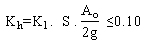 (1) (1)
where:
K1 = importance factor defined in table 11.
S = soil coefficient defined in table 9.
Ao = peak ground acceleration defined in table 8.
g = acceleration due to gravity (32 ft/s2 (9.8 m/s2)).
Table 11. Importance factor, K1
Importance coefficient |
K1 |
I |
1.0 |
II |
0.8 |
In this method, all structural components are designed to be elastic, which means the response modification factor is equal to one. The analysis is done for both the longitudinal and transverse directions.
B.1.1.2 Seismic Coefficient Method Modified by Structural Response
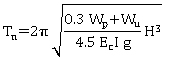
This method is applied to simply supported bridges of more than two spans (spans lengths less than 230 ft (70 m)) and substructure heights less than 82 ft (25 m) including the maximum scour effect. The horizontal seismic coefficient Kh is calculated as shown in equation 2.
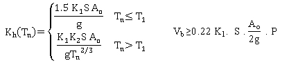 (2) (2)
where:
K2,T1 = spectral constants, defined in table 12.
Tn = natural period determined using simplified formulas (table 13) or exact methods.
Vb = total base shear in the bridge.
P = total weight of the bridge.
Table 12. Spectral constants, T1 and K2.
Soil type |
T1 |
K2 |
I |
0.20 |
0.513 |
II |
0.30 |
0.672 |
III |
0.70 |
1.182 |
IV |
1.10 |
1.598 |
Table 13. Approximate formulas for natural periods for bridges.
Structural system |
Direction |
Fundamental period |
Simply supported bridges |
Longitudinal or transverse |
Reinforced concrete support |
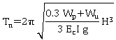
|
Continuous bridges with fix supports on intermediate substructure and rigid abutments. One superstructure end on a fix support |
Transverse1 |
Reinforced concrete |
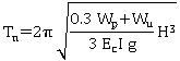
|
Steel |
|
Longitudinal |
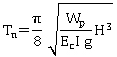
|
B.1.1.3 Modal Spectral Method
This method is applied to tall bridges with simple supported continuous bridges (spans lengths less than 230 ft (70 m)) and substructure heights greater than 82 ft (25 m) including the maximum scour effect. This method may be used in place of the seismic coefficient method and the seismic coefficient method modified by structural response.
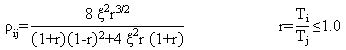
The absolute spectral acceleration for the vibration mode m, Sa(Tm) is calculated using equation 3.
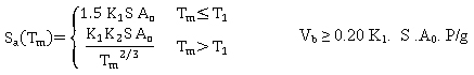 (3) (3)
where:
Tm = period of mode m.
The displacements, rotations, and forces in each structural element are calculated in both the longitudinal and transverse directions from the contributions of each of the vibration modes. The combination of the maximum modal values to obtain elastic response values are calculated using the expressions shown in equation 4 and equation 5.
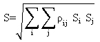 (4) (4)
 (5) (5)
where:
ΣiΣj = summation of the contribution of the considered modes.
ρij = coupling factor.
Ti, Tj = modal periods.
ς = damping ratio and taken equal to 0.05.
The number of modes to be included in the analysis is chosen such that the summation of the effective mass ratios will be larger than 90 percent.
B.1.1.4 Modal Spectral Method Using Site-Specific Spectra
In special cases, MOP requires that the design of a bridge is based on the modal spectral method of analysis based and a spectrum developed for the specific site.
B.1.1.5 Linear and Nonlinear Time History Analysis
In specific cases, especially for bridges incorporating base isolation systems, MOP requires time history analysis, either linear or nonlinear, using synthetic accelerograms reflecting the site seismic risk and the soil conditions.
B.1.2 Response Modification Factors (R)
The design seismic forces for members and connections are calculated by dividing the elastic response values by a response modification factor R. Special detailing is required to accommodate inelastic behavior and the formation of plastic hinges when R factors greater than 1 are used. Values of these factors are summarized in table 14 for the longitudinal and transverse directions.
Table 14. Response modification factors (R).
Element |
Longitudinal |
Transverse |
Supports
Wall-type pier
Single column with foundation cap
Column bent with foundation cap
Inclined column with foundation cap
|
3
3
3
3
|
2
3
4
2
|
Piles or micropiles
Individual
Batter piles
Inclined batter piles |
3
3
3
|
3
4
2
|
Foundations1
Spread footing
Batter of piles
Drilled shaft
Caisson or foundation pile |
1
1
1
1
|
1
1
1
1
|
Connections2
Expansion joint
Bearing plate
Shear key
Bearing |
0.8
0.8
1
1
|
0.8
0.8
1
1
|
B.1.3 Determination of Elastic Forces and Displacements
For bridges classified in seismic categories C or D, the elastic forces and displacement are calculated in both the longitudinal and transverse directions. For the case of curved bridges, the longitudinal direction is the chord joining the abutments.
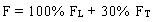
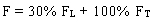
B.1.4 Combination of Forces in Two Perpendicular Directions
The forces calculated independently in two perpendicular directions are combined to take in account the uncertainty in the direction of the seismic waves and the effect of the two horizontal components of the earthquake. Two load stages are considered. Load stage I is shown in equation 6, and load stage II is shown in equation 7.
 (6) (6)
 (7) (7)
where:
F = absolute value of force or moment for all structural members due to load combination.
FL = absolute value of force or moment in the longitudinal direction.
FT = absolute value of force or moment in the transverse direction.
B.1.5 Minimum Support Length
Minimum values for support lengths of beams are shown in equation 8 for seismic behavior categories A and B and in equation 9 for seismic behavior categories C and D.
 (8) (8)
 (9) (9)
where:
L = length of the bridge deck to the adjacent expansion joint, or to the end of the bridge deck; for hinges within a span, L is the sum of the distances to either side of the hinge; for single-span bridges, L is the length of the bridge deck (m).
 = angle of skew of support measured from a line normal to span (degrees). = angle of skew of support measured from a line normal to span (degrees).
H = 0 for abutments and single-span bridges; average height of columns supporting the bridge deck from the abutment to the next expansion joint (m); pier height (m) for columns and piers; average height of the adjacent two columns or piers (m) at hinges within a span.
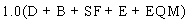
B.1.6 Modified Design Forces for Structural Elements and Connections
The seismic design forces from load stages I and II are divided by the R factors to obtain modified design forces. These modified forces are combined with other loads to obtain the maximum load combination as shown in equation 10.
 (10) (10)
where:
D = dead load.
B = buoyancy.
SF = stream-flow pressure.
E = earth pressure.
EQM = elastic seismic forces for the load stages I and II divided by R.
B.1.7 Modified Design Forces for Foundations
The seismic design forces for spread footings, pile caps and micropiles shall be those from load stages I and II divided by the response modification factor R = 1 to obtain modified design forces. These modified forces are combined with other loads to obtain the maximum load combination as previously shown in equation 10.
The load combinations are based on division I-A of AASHTO's Standard Specifications.(10)
B.1.8 Seismic Design of Foundations, Abutments, and Retaining Walls
The specifications for the seismic design of these elements are covered in section 3.1003 of the Highway Handbook.(11)
B.1.9 Seismic Design of Reinforced Concrete Elements
The design and construction of CIP reinforced concrete elements (columns, foundations, and connections) are required to satisfy the provisions of division I-A of the AASHTO specifications.
If the design is based on the allowable stress method, all the stresses are increased by 33.3 percent. If this method is used for bridges in seismic categories C and D, conservative designs are to be expected unless the design is based on the maximum forces developed from plastic hinging.
B.1.9.1 Requirements for Columns
Section 7.6.2 of division I-A of the AASHTO specifications for seismic performance category C and D is followed.
B.1.9.2 Columns and/or Piers
Section 7.6.3 of division I-A of the AASHTO specifications for seismic performance category C and D is followed.
B.1.9.3 Column Connections
Section 7.6.4 of division I-A of the AASHTO specifications for seismic performance category C and D is followed.
B.1.9.4 Construction Joints in Piers and Columns
Section 7.6.5 of division I-A of the AASHTO specifications for seismic performance category C and D is followed.
B.1.9.5 Reinforced Concrete Micropiles
These elements are designed for elastic forces (R = 1). Alternatively, these elements may be designed using the maximum forces from the column or pier plastic hinges.
B.1.10 Forces from Plastic Hinges on Piers or Columns
Design forces for columns, piers, and foundations are determined from the maximum forces due to plastic hinges. The procedure for calculation of these forces is based on section 7.2.2 of division I-A of the AASHTO specifications.
B.1.11 Diaphragms
Due to the high values of vertical acceleration in seismic zone 3, the beams of bridges in this zone are connected by transverse beams (diaphragms).
B.1.12 Anchor Bars (Seismic Bars)
No.7 (22 mm) deformed bars are provided to resist a vertical seismic coefficient of Kv = Ao/4g. These bars are required to satisfy the provisions of ASTM A706. ASTM A 615M bars are permitted if the difference between the true yield force and the nominal value is less than 17.4 ksi (120 MPa) and the relationship between ultimate stress and yield stress is less than 1.25.
B.1.13 Lateral Stoppers (Shear Keys)
To avoid excessive lateral displacement of the superstructure due to seismic forces, lateral stoppers are provided on bent caps. The design force used for these stoppers is the seismic force acting in the transverse direction divided by four. These stoppers are required to have sufficient ductility to avoid the deck collapse. The height of these shear keys is required to be greater than 12 inches (300 mm) and a gap between the shear key and the superstructure is provided to accommodate the seismic displacement plus 2 inches (50 mm).
B.1.14 Seismic Joints
Seismic joints between deck segments have a minimum spacing to allow the displacements of the elastomeric bearings. The minimum spacing is given by equation 11:
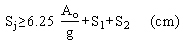 (11) (11)
where S1 and S2 are the seismic displacements of each of the elastomeric bearings in cm.
B.1.15 Seismic Isolation Systems
Seismic isolation systems used as supporting elements are designed and tested according to AASHTO's Guide Specifications for Seismic Isolation Design.(21)
B.2 SEISMIC DESIGN REQUIREMENTS FOR WALLS
Walls that are part of the public transportation system controlled by MOP are generally designed in accordance with the AASHTO Standard Specifications.(10) PGAs given in the Chilean design guide for wall design are used (i.e., PGAs of 0.2, 0.3, or 0.4 g in zones 1, 2, or 3, respectively). MOP requirements allow concrete gravity walls to be designed for a reduced acceleration, providing that the wall can slide during shaking. For MSE walls however, MOP requirements do not allow the design acceleration to be reduced for internal and external wall stability. For walls not under MOP jurisdiction, design accelerations may be established as a site-specific value. In general, however, even these walls are designed using the AASHTO Standard Specifications.(10)
For MSE walls, typical practice is to select good, frictional backfill materials and overexcavate poorer soils, replacing them with the backfill materials. Because of this practice, a reinforcement length of 70 percent of the wall height is typically used to meet seismic design requirements.
|


