U.S. Department of Transportation
Federal Highway Administration
1200 New Jersey Avenue, SE
Washington, DC 20590
202-366-4000
Federal Highway Administration Research and Technology
Coordinating, Developing, and Delivering Highway Transportation Innovations
| REPORT |
| This report is an archived publication and may contain dated technical, contact, and link information |
|
| Publication Number: FHWA-HRT-14-090 Date: October 2014 |
Publication Number: FHWA-HRT-14-090 Date: October 2014 |
The test results from the physical testing of the pullout specimens are presented in this chapter. The terminology and specimen notation used in this study are first introduced. Then the cracking and damage mechanisms in bond for the pullout specimens are presented. Following that, the parameters that could affect bond performance, including casting orientation, embedment length, side cover, bar spacing, UHPC compressive strength, reinforcing bar size, and reinforcing bar type are analyzed and discussed. The test matrix, including all the information of the specimen design, UHPC compressive strength, and bar stress at bond failure, is reported in each section.
Consistent terminology is used throughout this report in order to simplify the discussion of results. In terms of the bar stress versus bar slip response, the applied load and bar displacement were continuous recorded during the pullout test. The bar stress fs was then calculated as the applied load divided by the cross section area of the reinforcing bar. The displacement was measured along a loaded portion of the reinforcing bar at about two inches (5.1 cm) above the top surface of UHPC strip (shown in Figure 7). This displacement is used as a measure of the bar slip, with the understanding that the displacement also included the stretching of the reinforcing bar under the pullout force. The bar stress is plotted versus slip to characterize the bond behavior and a typical bar stress versus slip curve for reinforcing bar in UHPC in this study is presented in Figure 9.
As shown in Figure 9, the point with the maximum bar stress was marked with (fs,max, s1), which refers to the bar stress and slip, respectively, at bond failure. During each test, the specimen surface was also continuously checked for signs of cracks and the bar stress at first observed crack was reported as fs,crack. Due to safety considerations, visual inspection was stopped when the load was close the estimated maximum load. In some cases, visual inspection was stopped before the first crack was observed. The bar stress at first observed crack (fs,crack), the maximum bar stress at bond failure (fs,max), and the bar slip at bond failure (s1) were reported for each specimen.

Figure 9. Illustration. Conceptual bar stress versus slip response.
Another term that has been often used in the report is the average bond strength at bond failure, µTEST. In general, the load transfer between the reinforcing bar and the surrounding concrete materials is assumed as following. At the beginning of the axial loading of the reinforcing bar, the outermost lug exerts a bearing force on the surrounding concrete materials and this bearing force at the outermost lug plus the friction force and chemical adhesion contribute to the bond strength at this stage. As load increases, this bearing force causes crushing of concrete materials in the vicinity of the outermost lug, the bar slips, and most of the friction force and chemical adhesion are lost. The slip causes the bearing reaction of next adjacent lugs, which contribute to the resisting the applied axial load. At ultimate load, it is assumed that all the lugs bear against concrete and help resist the axial load and that the bond stress distribution is uniform. The average bond strength can be calculated by dividing the bond force at failure by the overall contact area, using the equation in Figure 10

Figure 10. Equation. Average bond stress in reinforcing bar.
In this equation, ƒs,max is the bar stress at bond failure, db is the bar diameter, and ld is the embedment length. The bond stress distribution for reinforcing bar in UHPC will be discussed in the later section where the effect of embedment length is investigated.
As mentioned in the introduction and also will be discussed in later sections, there are many factors that affect bond strength. The main parameters that this study investigated include the bar type and size, embedment length, side cover, bar spacing, and UHPC compressive strength. The specimens are named in a manner to be able illustrate all these variables. The specimen notation will be explained in an example in the following. Given an example specimen named B5-L6d-S2d-Sp4-1D-B2S1, the first term B5 represents the type and the size of the reinforcing bar, and the letter is for the bar type (B for uncoated black reinforcing bar, M for A1035 high strength reinforcing bar, E for epoxy coated reinforcing bar) and the number is for the bar size (for example, 5 for No. 5 bar); L6d represents a designed embedment length of six times of the testing bar diameter; S2d represents a designed side cover of two times of the testing bar diameter; Sp4 represents a designed center to center spacing of 4 in. (10.2 cm) between the testing bar and the nearest No.8 splice bar extending from the precast slab;1D represents the age (days) of the UHPC material at testing, which is one day in the example; B2S1 represents the Batch No. 2 of the UHPC casting and the specimens were cast on the precast Slab No. 1. The actual measurement of UHPC compressive strength at testing (f'c), bar embedment length (ld), bar spliced length (ls), side cover (cso), and clear spacing to nearest No. 8 bar (2csi) are reported. The same notation will be used through the study.
It should be noted that the embedment length and side cover are defined in terms of bar diameter while the bar spacing is defined in terms of actual measurement in inches. The decision to define bar spacing in terms of a physical measurement results from the fact that the No. 8 bars extending from the precast slabs were spaced at either 8 or 12 in. (203 or 305 mm). In many cases, the testing bar was placed in the middle of the two No. 8 bars, therefore, the center-to-center spacing was either 4 or 6 in. (102 or 152 mm).
In general, the transfer of force from the reinforcing steel to the surrounding concrete is mainly through mechanical anchorage or bearing of the reinforcing bar ribs against the concrete surface, with chemical adhesion and frictional forces between the bar and the concrete playing a minimal role. For the pullout tests in this study, the reinforcing bar are lap spliced, as shown in Figure 11a, and the force on the testing bar is transferred to the concrete, which, in turn, transferred the force to adjacent No. 8 bars that extend from the precast concrete slab. The tensile forces due to this bearing effect could cause crack openings in a diagonal direction, as shown in Figure 11b. The wedging action of the deformations on the reinforcing bar could also cause hoop tensile stresses which can initiate splitting cracks as shown in Figure 11b.

Figure 11. Illustration. Pullout tests: (a) forces on bars; and (b) crack patterns.
For tests in this study wherein the failure was not caused by reinforcing bar tensile rupture, the majority of the tests expressed a bond failure associated with splitting cracks, either split to the adjacent No.8 bars (Figure 12a), or to the side face (Figure 12b), or both (Figure 12c). In some cases, a UHPC tensile failure was observed wherein the tensile force separates a roughly planar region of concrete from the rest of the specimen, as shown in Figure 12d. In general, the specimens with UHPC tensile failures had smaller concrete side cover, demonstrating less bond strength than those with splitting failures. It should be noted that in cases with splitting failure, diagonal cracks would still form but would not be the control failure mode as shown in Figure 13. Figure 13a shows a few conical cracks observed with unaided vision; on this same specimen, when denatured alcohol was sprayed on the surface, more diagonal cracks appeared after the denatured alcohol evaporated from the surface, as shown in the Figure 13b. In almost all cases, the diagonal cracks like those in Figure 13 were observed. Conical surface failure around the reinforcing steel, as shown in Figure 14, was also observed in some cases.
In most structural applications, splitting failure is more common (ACI 408 R-03) (17) and the majority of the tests in this study failed with splitting cracks. When the effect of different parameters on bond strength is evaluated in later sections of this chapter, the analysis only includes those with splitting failures (Figure 12a, b, and c) and those failed with splitting cracks combined with small conical surfaces failures (Figure 14). In the section where the design recommendations are developed, the specimens with UHPC tensile failures and the specimens with bar rupture are also included in the analysis.

Figure 12. Photo. Crack patterns: (a) longitudinal splitting cracks to adjacent No. 8 bars; (b) splitting cracks to side face; (c) splitting cracks to side face and adjacent No. 8 bars; and (d) UHPC tensile failure with opened diagonal cracks.

Figure 13. Photo. Diagonal crack observation: (a) visual inspection; and (b) crack inspection with denatured alcohol.

Figure 14. Photo. Conical surface failure: (a) conical surface around the bar; and (b) conical surface extended to the side face.
The factors affecting bond performance will be discussed in this section. The effect of casting orientation will be first presented. Then the parameters, including embedment length, concrete side cover, bar spacing, UHPC compressive strength, bar size, bar type, and bar yield strength, are evaluated.
Two casting orientations, either cast on side or cast upright (see Figure 8), were compared. It should be noted that, other than the casting orientation, each pair of the comparison specimens were identical specimens that were cast at the same time. A total of nine pairs of specimens were tested and the results are presented in Table 4.
As shown in Table 4, there was no appreciable difference between side-cast specimens and upright-cast specimens in eight of the nine pairs. In the one remaining pair, a difference of 19.7% was observed. For the purpose of easy construction and casting, the upright orientation was used in the rest of the study.
In this early stage of investigation, it was noted that with an embedment length of only 6db and side cover of 2db (specimensB5-L6d-S2d-Sp4-1D-B2S1 and B5-L6d-S2d-Sp4-1D-B2S2), the bond strength was already close to, or even beyond the yield strength of Grade 60 uncoated bar. To minimize the effect of bar yielding on bond strength when investigating other factors, the majority of the tests were conducted using A1035 high strength bar. The effect of reinforcing bar yielding before bond failure on bond strength will be discussed in the later section where the reinforcing bar type was evaluated.
During the investigation, it was also noted that the very end specimens that are close to the casting point (where the large majority of the UHPC is poured into the formwork) consistently displayed lower bond strength than specimens at the other positions. This is probably due to the variation of fiber distribution inside the UHPC. The results from the end specimens close to casting point are included in the section wherein the design recommendations are developed, but excluded from the sections of the report wherein the effect of different design parameters (ld, cso, csi, f'c, etc.) on bond strength is analyzed.
Table 4. Test Specimens – Effect of Casting Orientation
| Cast Orientation* | Batch ID† | ƒ'c, ksi | ld, in. | ls, in. | cso, in. | csi,, in. | ƒs,max, ksi | s, in. | ƒs,crack, ksi | µTEST, ksi | Difference, % |
|---|---|---|---|---|---|---|---|---|---|---|---|
| Upright Side |
B5-L6d-S2d-Sp4-1D-B2S1
B5-L6d-S2d-Sp4-1D-B2S2 |
13.4 13.4 |
3.8 3.9 |
2.8 2.9 |
1.1 1.2 |
1.5 1.3 |
82 67 |
0.091 0.061 |
NA 20 |
3368 2706 |
-19.7 |
| Upright Side |
B5-L8d-S2d-Sp4-1D-B2S1 B5-L8d-S2d-Sp4-1D-B2S2 |
13.4 13.4 |
5.3 5.1 |
4.3 4.1 |
1.2 1.4 |
1.5 1.5 |
96 95 |
0.205 0.215 |
24 NA |
2857 2936 |
2.8 |
| Upright Side |
B5-L10d-S2d-Sp4-1D-B2S1 B5-L10d-S2d-Sp4-1D-B2S2 |
13.4 13.4 |
6.3 6.3 |
5.3 5.3 |
1.2 1.4 |
1.6 1.5 |
94 88 |
0.128 0.167 |
22 NA |
2335 2189 |
-6.2 |
| Upright Side |
M5-L12d-S2d-Sp4-1D-B2S1 M5-L12d-S2d-Sp4-1D-B2S2 |
13.4 13.4 |
7.6 7.6 |
6.6 6.6 |
1.2 1.3 |
1.5 1.6 |
127 129 |
0.103 0.090 |
33 30 |
2603 2645 |
1.6 |
| Upright Side |
B5-L8d-S2d-Sp4-7D-B2S1 B5-L8d-S2d-Sp4-7D-B2S2 |
19.5 19.5 |
5.1 5.1 |
4.1 4.1 |
1.1 1.4 |
1.5 1.6 |
94 96 |
0.162 0.184 |
21 20 |
2913 2933 |
0.7 |
| Upright Side |
B5-L8d-S2d-Sp4-7D-B2S1 B5-L8d-S2d-Sp4-7D-B2S2 |
19.5 19.5 |
5.1 5.1 |
4.1 4.1 |
1.1 1.4 |
1.5 1.6 |
95 97 |
0.078 0.075 |
NA NA |
2922 2947 |
0.8 |
| Upright Side |
B5-L10d-S2d-Sp4-7D-B2S1 B5-L10d-S2d-Sp4-7D-B2S2 |
19.5 19.5 |
6.3 6.3 |
5.3 5.3 |
1.2 1.3 |
1.4 1.6 |
rupture‡ rupture‡ |
0.269 0.262 |
27 NA |
- - |
- |
| Upright Side |
B5-L10d-S2d-Sp4-7D-B2S1 B5-L10d-S2d-Sp4-7D-B2S2 |
19.5 19.5 |
5.9 6.3 |
4.9 5.3 |
1.2 1.4 |
1.4 1.6 |
rupture‡ rupture‡ |
0.161 0.197 |
21 24 |
- - |
- |
| Upright Side |
M5-L12d-S2d-Sp4-7D-B2S1 M5-L12d-S2d-Sp4-7D-B2S2 |
19.5 19.5 |
7.6 7.5 |
6.6 6.5 |
1.2 1.4 |
1.4 1.5 |
rupture‡ rupture‡ |
0.135 0.152 |
27 NA |
- - |
- |
* Refer to Figure 8. ‡ Bar ruptured before bond failure. 1 ksi = 6.895 MPa; 1 in. = 2.54 cm
† The column headings are defined as follows:
The effect of embedment length on bond strength is analyzed in this section. It was evaluated by varying the embedment length while keeping other factors constant, including side cover, bar spacing, and concrete compressive strength. The test matrix is presented in Table 5. A total of 37 tests (grouped into four sets) were included and all specimens used A1035 No. 5 bar. In the first set, the embedment lengths included 4db, 6db, 8db, and 10db; the side cover was designed to be constant at 2db; the center-to-center spacing between the testing bar and the nearest No. 8 bar was kept constant at 4 in. (10 cm); and the tests were conducted at one day after casting when the UHPC compressive strength averaged 13.7 ksi (90 MPa). In Set 2, similar specimens as those in Set 1 were tested except that the specimens were tested at seven days after casting and the compressive strength averaged 19.4 ksi (133 MPa). In Sets 3 and 4, while the embedment length was varied, the side cover was increased to 3.5db and 3db, respectively, compared with 2db in Sets 1 and 2. More details of the specimen design and actual measurement are presented in Table 5.
The bar stress at bond failure versus the embedment length for all the specimens is plotted in Figure 15. As shown in Figure 15, increasing the embedment length of a reinforcing bar increases the bond strength. The relationship between the bar stress at bond failure and the bonded length is nearly linear, similar to that observed in normal strength concrete (ACI 408 R-03)(17). The linear relationship between bond force and the bonded length in normal strength concrete is often explained based on the assumption that all lugs bear against concrete at the ultimate stage and help in resisting the applied axial force, therefore at ultimate the bond stress distribution is nearly uniform. However, the bond stress distribution in high strength conventional concrete, with compressive strength over 13 ksi (90 MPa) and without fiber reinforcement, was found to be not uniform based on a study conducted by Azizinamini et al. (19) Azizinamini et al. noted that for high strength concrete, the increase in bearing capacity is more than the increase in tensile strength, which in turn, would prevent crushing of the concrete in the vicinity of each lug to the extent that would otherwise take place in normal strength concrete. In other words, the high strength concrete would crack before crushing due to the less than proportional increase in tensile strength compared with bearing capacity. All lugs may not participate in resisting applied axial load before the concrete cracks, and the first few lugs contribute the most. The linear relationship observed in this study implies that the behavior attributed to conventional high strength concretes by Azizinamini et al.(19) may not be present in UHPC, potentially due to the enhanced pre- and post-cracking tensile response of the UHPC.
Table 5. Test specimens – effect of embedment length.
| Batch ID | f'c, ksi | ld, in. | ls, in. | cso, in. | csi, in. | fs,max, ksi | s1, in. | fs,crack, ksi | |
|---|---|---|---|---|---|---|---|---|---|
| Set 1 | M5-L4d-S2d-Sp4-1D-B5S2 | 13.9 | 2.56 | 1.56 | 1.19 | 1.53 | 43 | 0.033 | NA |
| M5-L4d-S2d-Sp4-1D-B5S2 | 13.9 | 2.69 | 1.69 | 1.20 | 1.56 | 49 | 0.020 | NA | |
| M5-L6d-S2d-Sp4-1D-B3S1 | 13.2 | 3.69 | 3.44 | 1.16 | 1.56 | 77 | 0.042 | 45 | |
| M5-L6d-S2d-Sp4-1D-B4S2 | 13.6 | 3.81 | 3.56 | 1.16 | 1.38 | 84 | 0.053 | 42 | |
| M5-L6d-S2d-Sp4-1D-B4S2 | 13.6 | 3.81 | 2.81 | 1.29 | 1.38 | 82 | 0.053 | 58 | |
| M5-L8d-S2d-Sp4-1D-B3S1 | 13.2 | 5.00 | 4.00 | 1.23 | 1.44 | 96 | 0.065 | 58 | |
| M5-L8d-S2d-Sp4-1D-B6S3 | 13.9 | 4.60 | 3.60 | 1.25 | 1.47 | 108 | 0.057 | 68 | |
| M5-L8d-S2d-Sp4-1D-B8S4 | 13.8 | 4.94 | 3.94 | 1.10 | 1.53 | 106 | 0.050 | NA | |
| M5-L8d-S2d-Sp4-1D-B9S4 | 13.7 | 5.25 | 4.25 | 1.18 | 1.41 | 121 | 0.065 | 77 | |
| M5-L10d-S2d-Sp4-1D-B6S3 | 13.9 | 6.25 | 5.25 | 1.18 | 1.47 | 144 | 0.082 | 77 | |
| M5-L10d-S2d-Sp4-1D-B6S3 | 13.9 | 6.38 | 5.38 | 1.24 | 1.40 | 113 | 0.075 | 61 | |
| M5-L10d-S2d-Sp4-1D-B9S4 | 13.7 | 6.31 | 5.31 | 1.17 | 1.53 | 132 | 0.076 | 65 | |
| Set 2 | M5-L4d-S2d-Sp4-7D-B1S1 | 19.9 | 2.36 | 1.36 | 1.18 | 1.49 | 67 | 0.036 | NA |
| M5-L4d-S2d-Sp4-7D-B3S1 | 19.5 | 2.44 | 2.19 | 1.21 | 1.44 | 59 | 0.041 | 40 | |
| M5-L6d-S2d-Sp4-7D-B1S1 | 19.9 | 3.29 | 2.29 | 1.37 | 1.65 | 91 | 0.072 | NA | |
| M5-L6d-S2d-Sp4-7D-B3S1 | 19.5 | 3.75 | 3.50 | 1.25 | 1.56 | 91 | 0.068 | 52 | |
| M5-L6d-S2d-Sp4-7D-B3S1 | 19.5 | 3.81 | 2.81 | 1.20 | 1.50 | 90 | 0.052 | 58 | |
| M5-L6d-S2d-Sp4-7D-B4S2 | 19.2 | 3.88 | 2.88 | 1.14 | 1.44 | 83 | 0.047 | 65 | |
| M5-L8d-S2d-Sp4-7D-B3S1 | 19.5 | 5.06 | 4.06 | 1.22 | 1.56 | 114 | 0.059 | 58 | |
| M5-L8d-S2d-Sp4-7D-B9S4 | 18.8 | 5.00 | 4.00 | 1.12 | 1.50 | 127 | 0.070 | NA | |
| M5-L10d-S2d-Sp4-7D-B9S4 | 18.8 | 6.12 | 5.12 | 1.11 | 1.56 | 154 | 0.100 | NA | |
| M5-L10d-S2d-Sp4-7D-B9S4 | 18.8 | 6.06 | 5.06 | 1.15 | 1.47 | 153 | 0.115 | NA | |
| M5-L10d-S2d-Sp4-7D-B3S1 | 19.5 | 6.19 | 5.19 | 1.17 | 1.50 | 145 | 0.091 | 74 | |
| Set 3 | M5-L6d-S3.5d-Sp4-1D-B4S2 | 13.6 | 3.88 | 3.63 | 2.24 | 1.63 | 96 | 0.043 | NA |
| M5-L6d-S3.5d-Sp4-1D-B4S2 | 13.6 | 3.81 | 2.81 | 2.25 | 1.56 | 90 | 0.045 | 79 | |
| M5-L8d-S3.5d-Sp4-1D-B4S2 | 13.6 | 5.06 | 4.06 | 2.35 | 1.56 | 136 | 0.080 | 65 | |
| M5-L8d-S3.5d-Sp4-1D-B7S3 | 13.5 | 5.13 | 4.13 | 2.08 | 1.56 | 137 | 0.068 | 97 | |
| M5-L10d-S3.5d-Sp4-1D-B4S2 | 13.6 | 6.31 | 6.06 | 2.20 | 1.56 | 155 | 0.108 | 90 | |
| M5-L10d-S3.5d-Sp4-1D-B4S2 | 13.6 | 6.31 | 5.31 | 2.24 | 1.63 | 166 | 0.161 | 68 | |
| M5-L10d-S3.5d-Sp4-1D-B4S2 | 13.6 | 6.31 | 5.31 | 2.33 | 1.56 | 158 | 0.099 | 125 | |
| Set 4 | M5-L6d-S3d-Sp4-1D-B10S4 | 13.9 | 3.44 | 2.44 | 1.82 | 1.50 | 85 | 0.037 | NA |
| M5-L6d-S3d-Sp4-1D-B10S4 | 13.9 | 3.75 | 2.75 | 1.83 | 1.53 | 84 | 0.051 | NA | |
| M5-L6.7d-S3d-Sp4-1D-B10S4 | 13.9 | 4.22 | 3.22 | 1.87 | 1.59 | 103 | 0.045 | NA | |
| M5-L6.7d-S3d-Sp4-1D-B10S4 | 13.9 | 4.13 | 3.13 | 1.85 | 1.50 | 115 | 0.060 | NA | |
| M5-L8d-S3d-Sp4-1D-B10S4 | 13.9 | 5.44 | 4.44 | 1.92 | 1.50 | 138 | 0.072 | NA | |
| M5-L8d-S3d-Sp4-1D-B10S4 | 13.9 | 5.25 | 4.25 | 1.86 | 1.59 | 134 | 0.080 | NA | |
| M5-L10d-S3d-Sp4-1D-B10S4 | 13.9 | 6.13 | 5.13 | 1.83 | 1.50 | 141 | 0.053 | NA |
Note: For explanation of the specimen ID and each parameter, see note for Table 4. 1 ksi = 6.895 MPa; 1 in. = 2.54 cm.

Figure 15. Graph. Effect of embedment length: fs,max versus embedment length ld.
Concrete cover and bar spacing play important roles in bond strength. An understanding of the bond behavior in normal non-fiber reinforced concrete is necessary. As stated in ACI 408 R-03(17), for bond failure involving splitting of the concrete, the nature of the splitting failure depends on whether the concrete cover, cso, is smaller than csi, which is 1/2 of the clear spacing to adjacent bar. The demonstration of cso and csi is presented in Figure 16 and also in Figure 3 in Chapter 2. When cso is smaller than csi, the splitting crack occurs through the cover to the free surface, as shown in Figure 16a. When csi is smaller than cso, the splitting crack forms between the reinforcing bars as shown in Figure 16b. In ACI 318 Building Code Requirements for Structural Concrete,(21) the actual values of csi are used for development length calculations. In the Canadian requirements for reinforced concrete design (CSA standard A23.3-94),(21) a larger value defined as [(4/3)csi +(1/6)db] is used. Zuo and Darwin (1998) (22) suggested using either 1.6csi when using a multiple of csi or using csi + 0.25 in. (csi + 6.4 mm) when a constant value is added to csi. Darwin et al. (1996a) (23) explained that the reason why a larger value than the actual value of csi is used is most likely “due to the longer effective crack lengths that occur when concrete splits between bars.” The presence of fiber reinforcement in UHPC can be expected to increase the resistance to splitting crack between bars and thus an even larger value than the actual value of csi between bars may be necessary. In the present analysis, both the term csi representing 1/2 of the clear spacing as well as the actual clear spacing, 2csi, are compared with side cover cso.
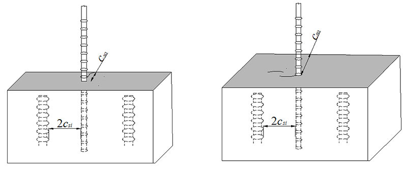
Figure 16. Illustration. Bond splitting cracks: (a) csi > cso; and (b) csi < cso.
Within this study, a total of 37 specimens were tested in five sets and the results are presented in Table 6. Using the same philosophy that has been used in previous sections, the specimens were designed to have the same parameters except for side cover. A1035 No. 5 bars were used and all specimens were designed to have the same bar spacing to the nearest No. 8 bar. As shown in Table 6, for Set 1 an embedment length of 6db was used and the side cover included nominal values of 2db, 2.7db, 3db, and 3.5db [corresponding to UHPC strip widths of 3 1/8, 4, 4 3/8, and 5 in. (7.9 to 10.2, 11.1 and 12.7 cm), respectively]. Set 2 had the same design as Set 1, except that the embedment length was increased to 8db. In Set 3, specimens with a constant embedment length of 10db and a varied side cover of 2db and 3.5db were tested. All specimens in Sets 1, 2, and 3 were tested at one day after UHPC casting, with an average compressive strength of 13.7 ksi (94 MPa). Specimens in Sets 4 and 5 were tested at seven days after the UHPC casting, with an average compressive strength of 19.4 ksi (133 MPa). Specimens in Set 4 had an embedment length of 6db and side covers of 2db, 3db, and 3.5db, while specimens in Set 5 had an embedment length of 8db and side covers of 2db and 3.5db.
Based on the results shown in Table 6, it is clear that the maximum bar stress at bond failure increased as the side cover increased. For example, in Set 2 where a designed embedment length of 8db was used, the three specimens with a 2db side cover had bar stresses at bond failure of 108, 106, and 121 ksi (741, 729 and 833 MPa); when the side cover was increased to 3.5db, the two specimens had bar stresses at bond failure of 136 and 137 ksi (940 and 943 MPa).
Table 6. Test specimens – effect of side cover.
| Batch ID | f'c, ksi | ld, in. | ls, in. | cso, in. | csi, in. | fs,max, ksi | s1, in. | fs,crack, ksi | µTEST, ksi | |
|---|---|---|---|---|---|---|---|---|---|---|
| Set 1 | M5-L6d-S2d-Sp4-1D-B3S1 | 13.2 | 3.69 | 3.44 | 1.16 | 1.56 | 77 | 0.042 | 45 | 3269 |
| M5-L6d-S2d-Sp4-1D-B4S2 | 13.6 | 3.81 | 3.56 | 1.16 | 1.38 | 84 | 0.053 | 42 | 3430 | |
| M5-L6d-S2d-Sp4-1D-B4S2 | 13.6 | 3.81 | 2.81 | 1.29 | 1.38 | 82 | 0.053 | 58 | 3363 | |
| M5-L6d-S2.7d-Sp4-1D-B9S3 | 13.7 | 4.25 | 3.25 | 1.67 | 1.50 | 93 | 0.052 | 87 | 3420 | |
| M5-L6d-S2.7d-Sp4-1D-B9S3 | 13.7 | 4.13 | 3.13 | 1.66 | 1.53 | 98 | 0.057 | 90 | 3725 | |
| M5-L6d-S3d-Sp4-1D-B8S3 | 13.8 | 3.81 | 2.81 | 1.78 | 1.53 | 103 | 0.045 | 82 | 4211 | |
| M5-L6d-S3d-Sp4-1D-B8S3 | 13.8 | 3.81 | 2.81 | 1.78 | 1.56 | 88 | 0.039 | 86 | 3608 | |
| M5-L6d-S3d-Sp4-1D-B10S4 | 13.9 | 3.44 | 2.44 | 1.82 | 1.50 | 85 | 0.037 | NA | 3863 | |
| M5-L6d-S3d-Sp4-1D-B10S4 | 13.9 | 3.75 | 2.75 | 1.83 | 1.53 | 84 | 0.051 | NA | 3494 | |
| M5-L6d-S3.5d-Sp4-1D-B4S2 | 13.6 | 3.88 | 2.88 | 2.24 | 1.63 | 96 | 0.043 | NA | 3884 | |
| M5-L6d-S3.5d-Sp4-1D-B4S2 | 13.6 | 3.81 | 2.81 | 2.25 | 1.56 | 90 | 0.045 | 79 | 3707 | |
| Set 2 | M5-L8d-S2d-Sp4-1D-B6S3 | 13.9 | 4.60 | 3.60 | 1.25 | 1.47 | 108 | 0.057 | 68 | 3649 |
| M5-L8d-S2d-Sp4-1D-B8S4 | 13.8 | 4.94 | 3.94 | 1.10 | 1.53 | 106 | 0.050 | 0 | 3346 | |
| M5-L8d-S2d-Sp4-1D-B9S4 | 13.7 | 5.25 | 4.25 | 1.18 | 1.41 | 121 | 0.065 | 77 | 3595 | |
| M5-L8d-S2.7d-Sp4-1D-B9S3 | 13.7 | 5.31 | 4.31 | 1.55 | 1.47 | 129 | 0.074 | 87 | 3795 | |
| M5-L8d-S2.7d-Sp4-1D-B9S3 | 13.7 | 5.13 | 4.13 | 1.67 | 1.47 | 128 | 0.065 | 0 | 3906 | |
| M5-L8d-S3d-Sp4-1D-B8S3 | 13.8 | 5.13 | 4.13 | 1.49 | 1.47 | 134 | 0.073 | 95 | 4096 | |
| M5-L8d-S3d-Sp4-1D-B8S3 | 13.8 | 4.94 | 3.94 | 1.80 | 1.56 | 126 | 0.060 | 84 | 3974 | |
| M5-L8d-S3.5d-Sp4-1D-B4S2 | 13.6 | 5.06 | 4.06 | 2.35 | 1.56 | 136 | 0.080 | 65 | 4208 | |
| M5-L8d-S3.5d-Sp4-1D-B7S3 | 13.5 | 5.13 | 4.13 | 2.08 | 1.56 | 137 | 0.068 | 97 | 4168 | |
| Set 3 | M5-L10d-S2d-Sp4-1D-B6S3 | 13.9 | 6.25 | 5.25 | 1.18 | 1.47 | 144 | 0.082 | 77 | 3602 |
| M5-L10d-S2d-Sp4-1D-B9S4 | 13.7 | 6.31 | 5.31 | 1.17 | 1.53 | 132 | 0.076 | 65 | 3276 | |
| M5-L10d-S3.5d-Sp4-1D-B4S2 | 13.6 | 6.31 | 6.06 | 2.20 | 1.56 | 155 | 0.108 | 90 | 3843 | |
| M5-L10d-S3.5d-Sp4-1D-B4S2 | 13.6 | 6.31 | 5.31 | 2.24 | 1.63 | 166 | 0.161 | 68 | 4116 | |
| M5-L10d-S3.5d-Sp4-1D-B4S2 | 13.6 | 6.31 | 5.31 | 2.33 | 1.56 | 158 | 0.099 | 125 | 3911 | |
| Set 4 | M5-L6d-S2d-Sp4-7D-B1S1 | 19.9 | 3.29 | 2.29 | 1.37 | 1.65 | 91 | 0.072 | NA | 4326 |
| M5-L6d-S2d-Sp4-7D-B3S1 | 19.5 | 3.75 | 3.50 | 1.25 | 1.56 | 91 | 0.068 | 52 | 3812 | |
| M5-L6d-S2d-Sp4-7D-B3S1 | 19.5 | 3.81 | 2.81 | 1.20 | 1.50 | 90 | 0.052 | 58 | 3695 | |
| M5-L6d-S2d-Sp4-7D-B4S2 | 19.2 | 3.88 | 2.88 | 1.14 | 1.44 | 83 | 0.047 | 65 | 3335 | |
| M5-L6d-S3d-Sp4-7D-B10S4 | 19.6 | 3.94 | 2.94 | 1.85 | 1.66 | 118 | 0.058 | NA | 4673 | |
| M5-L6d-S3d-Sp4-7D-B10S4 | 19.6 | 3.88 | 2.88 | 1.85 | 1.56 | 111 | 0.055 | NA | 4486 | |
| M5-L6d-S3d-Sp4-7D-B10S4 | 19.6 | 4.19 | 3.19 | 1.89 | 1.53 | 117 | 0.050 | NA | 4359 | |
| M5-L6d-S3.5d-Sp4-7D-B4S2 | 19.2 | 3.75 | 3.50 | 2.31 | 1.56 | 117 | 0.051 | 106 | 4876 | |
| M5-L6d-S3.5d-Sp4-7D-B4S2 | 19.2 | 3.75 | 2.75 | 2.31 | 1.56 | 124 | 0.061 | 106 | 5148 | |
| Set 5 | M5-L8d-S2d-Sp4-7D-B3S1 | 19.5 | 5.06 | 4.06 | 1.22 | 1.56 | 114 | 0.059 | 58 | 3515 |
| M5-L8d-S2d-Sp4-7D-B9S4 | 18.8 | 5.00 | 4.00 | 1.12 | 1.50 | 127 | 0.070 | NA | 3979 | |
| M5-L8d-S3.5d-Sp4-7D-B4S2 | 19.2 | 5.00 | 4.00 | 2.27 | 1.56 | 145 | 0.096 | 87 | 4521 |
Note that specimens in Sets 1, 2, and 3 had the same design except for embedment length and side cover. The same is true for specimens in Sets 4 and 5. To create a bigger data pool, specimens in Sets 1, 2, and 3 and the specimens in Sets 4 and 5 are combined by converting bar stress at bond failure to bond stress to offset the effect of different embedment lengths (refer to equation in Figure 10). The bond stress is plotted versus side cover for specimens in Sets 1, 2 and 3 and specimens in Sets 4 and 5 in Figure 17 and Figure 18, respectively. With constant bar spacing (2csi) for all specimens, straight lines representing the point where the side cover cso is equal to csi and 2csi are included in the figures.
As shown in Figure 17 and Figure 18, the bond strength increases as the side cover increases. It is noted that when the side cover (cso) is bigger than half of the clear spacing (csi), the bond strength still increases as the side cover increases, instead of being controlled by the constant value of csi. This proves the early assumption that a greater bar spacing value than csi should be used due to the presence of the fibers. All specimens had side covers (cso) less than the clear bar spacing (2csi). It is reasonable to predict that when the side cover is large enough, the bar spacing would become the controlling factor and the bond strength would reach a plateau.
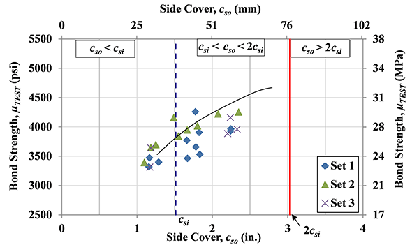
Figure 17. Graph. Effect of side cover: bond strength µTEST versus side cover for specimens in Sets 1, 2 and 3. The csi is constant.
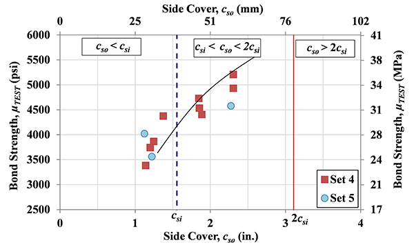
Figure 18. Graph. Effect of side cover: bond strength µTEST versus side cover for specimens in Sets 4 and 5. The csi is constant.
The effect of bar spacing on bond performance is analyzed in this section. Details for the specimens are presented in Table 7. A1035 bars were used and a total of 46 specimens were included in four sets. In each set of tests, the side cover (cso) and embedment length were designed to be constant while the bar spacing (csi) varied. It should be noted that the bar spacing to the nearest adjacent No. 8 bars was designed in terms of actual length in inches instead of bar diameter. In Set 1, a constant embedment length of 8db (A1035 No. 5 bar) and a constant side cover of 2db were used; the bar spacing, csi, varied from 0.1 to 5.7 in. (0.3 to 14.5 cm). All tests were conducted at one day after UHPC casting with an average compressive strength of 13.7 ksi (94.5 MPa). It should be pointed out that the specimens with a bar spacing of 0.1 in. (0.3 cm) were originally designed to have a contact lap splice, and the actual measurement indicated a bar spacing of 0.1 in. (0.3 cm). Given the small measured spacing value, these specimens were considered to have contact lap splices in the study.
All four sets specimens demonstrated similar trends and the results from Set 1 are discussed first here. As shown in Table 7, the bar stress at bond failure was only about 83 ksi (572 MPa) for a contact lap splice (the first two specimens in Set 1), and it increased to over 95 ksi (655 MPa) when csi was increased from zero to the range of 0.5 to 2.6 in. (1.3 to 6.6 cm). When csi was increased to over 3.5 in. (8.9 cm), the bar stress at bond failure dropped to as low as 70 ksi (483 MPa).
Table 7. Test specimens - effect of bar spacing
| Batch ID | f'c, ksi | ld, in. | ls, in. | cso, in. | csi, in. | fs,max, ksi | s1, in. | fs,crack, ksi | µTEST, ksi | |
|---|---|---|---|---|---|---|---|---|---|---|
| Set 1 | M5-L8d-S2d-Sp0-1D-B6S7 | 13.9 | 5.0 | 4.0 | 1.3 | 0.1 | 82 | 0.037 | NA | 2576 |
| M5-L8d-S2d-Sp0-1D-B6S7 | 13.9 | 5.1 | 4.1 | 1.2 | 0.1 | 83 | 0.036 | NA | 2575 | |
| M5-L8d-S2d-Sp2-1D-B11S4 | 13.6 | 5.1 | 4.1 | 1.2 | 0.5 | 119 | 0.050 | 77 | 3642 | |
| M5-L8d-S2d-Sp2-1D-B11S4 | 13.6 | 4.8 | 3.8 | 1.3 | 0.6 | 109 | 0.065 | 71 | 3594 | |
| M5-L8d-S2d-Sp4-1D-B3S1 | 13.2 | 5.0 | 4.0 | 1.2 | 1.4 | 96 | 0.065 | 58 | 2995 | |
| M5-L8d-S2d-Sp4-1D-B6S3 | 13.9 | 4.6 | 3.6 | 1.2 | 1.5 | 108 | 0.057 | 68 | 3649 | |
| M5-L8d-S2d-Sp4-1D-B8S4 | 13.8 | 4.9 | 3.9 | 1.1 | 1.5 | 106 | 0.050 | NA | 3346 | |
| M5-L8d-S2d-Sp6-1D-B3S6 | 13.2 | 5.1 | 4.1 | 1.4 | 2.6 | 101 | 0.075 | 52 | 3075 | |
| M5-L8d-S2d-Sp6-1D-B6S7 | 13.9 | 5.1 | 4.1 | 1.2 | 2.6 | 96 | 0.072 | 48 | 2965 | |
| M5-L8d-S2d-Sp6-1D-B6S7 | 13.9 | 5.0 | 4.0 | 1.3 | 2.6 | 95 | 0.074 | 58 | 2968 | |
| M5-L8d-S2d-Sp8-1D-B8S4 | 13.8 | 4.8 | 3.8 | 1.2 | 3.6 | 78 | 0.068 | 69 | 2545 | |
| M5-L8d-S2d-Sp8-1D-B8S4 | 13.8 | 5.0 | 4.0 | 1.2 | 3.5 | 82 | 0.066 | NA | 2571 | |
| M5-L8d-S2d-Sp8-1D-B11S4 | 13.6 | 5.0 | 4.0 | 1.2 | 3.5 | 86 | 0.076 | 57 | 2691 | |
| M5-L8d-S2d-Sp8-1D-B11S4 | 13.6 | 5.1 | 4.1 | 1.2 | 3.6 | 94 | 0.120 | 54 | 2866 | |
| M5-L8d-S2d-Sp12-1D-B6S7 | 13.9 | 5.0 | 4.0 | 1.3 | 5.6 | 70 | 0.081 | 45 | 2178 | |
| M5-L8d-S2d-Sp12-1D-B11S4 | 13.6 | 5.0 | 4.0 | 1.2 | 5.7 | 85 | 0.124 | 55 | 2646 | |
| Set 2 | M5-L8d-S3.5d-Sp0-1D-B7S7 | 13.5 | 4.9 | 3.9 | 2.1 | 0.1 | 105 | 0.000 | NA | 3372 |
| M5-L8d-S3.5d-Sp0-1D-B7S7 | 13.5 | 5.3 | 4.3 | 2.2 | 0.1 | 109 | 0.000 | NA | 3245 | |
| M5-L8d-S3.5d-Sp2-1D-B11S6 | 13.6 | 5.1 | 4.1 | 2.2 | 0.6 | 159 | 0.059 | 58 | 4858 | |
| M5-L8d-S3.5d-Sp2-1D-B11S6 | 13.6 | 5.1 | 4.1 | 2.2 | 0.7 | 149 | 0.084 | 68 | 4528 | |
| M5-L8d-S3.5d-Sp4-1D-B4S2 | 13.6 | 5.1 | 4.1 | 2.4 | 1.6 | 136 | 0.000 | NA | 4208 | |
| M5-L8d-S3.5d-Sp4-1D-B7S3 | 13.5 | 5.1 | 4.1 | 2.1 | 1.6 | 137 | 0.000 | NA | 4168 | |
| M5-L8d-S3.5d-Sp6-1D-B7S7 | 13.5 | 5.1 | 4.1 | 2.2 | 2.5 | 137 | 0.032 | 90 | 4180 | |
| M5-L8d-S3.5d-Sp6-1D-B7S7 | 13.5 | 5.3 | 4.3 | 2.1 | 2.4 | 145 | 0.048 | NA | 4314 | |
| M5-L8d-S3.5d-Sp8-1D-B7S3 | 13.5 | 5.2 | 4.2 | 2.0 | 3.4 | 115 | 0.131 | 81 | 3452 | |
| M5-L8d-S3.5d-Sp8-1D-B7S3 | 13.5 | 4.9 | 3.9 | 2.0 | 3.7 | 108 | 0.092 | 106 | 3434 | |
| M5-L8d-S3.5d-Sp12-1D-B7S7 | 13.5 | 5.1 | 4.1 | 2.2 | 5.8 | 129 | 0.080 | 65 | 3925 | |
| M5-L8d-S3.5d-Sp12-1D-B7S7 | 13.5 | 4.9 | 3.9 | 2.2 | 5.4 | 103 | 0.068 | 97 | 3288 | |
| M5-L8d-S3.5d-Sp12-1D-B11S6 | 13.6 | 5.1 | 4.1 | 2.2 | 5.5 | 107 | 0.082 | 74 | 3260 | |
| Set 3 | M5-L6d-S2d-Sp0-7D-B5S1 | 18.9 | 3.9 | 2.9 | 1.1 | 0.0 | 78 | 0.093 | 100 | 3142 |
| M5-L6d-S2d-Sp0-7D-B5S1 | 18.9 | 3.8 | 2.8 | 1.1 | 0.0 | 84 | 0.086 | 55 | 3506 | |
| M5-L6d-S2d-Sp2-7D-B5S1 | 18.9 | 3.8 | 2.8 | 1.1 | 0.6 | 88 | 0.079 | 81 | 3589 | |
| M5-L6d-S2d-Sp2-7D-B5S1 | 18.9 | 3.8 | 2.8 | 1.1 | 0.7 | 99 | NA | 81 | 4131 | |
| M5-L6d-S2d-Sp4-7D-B1S1 | 19.9 | 3.3 | 2.3 | 1.4 | 1.6 | 91 | 0.085 | 87 | 4326 | |
| M5-L6d-S2d-Sp4-7D-B3S1 | 19.5 | 3.8 | 2.8 | 1.2 | 1.6 | 91 | 0.112 | 61 | 3812 | |
| M5-L6d-S2d-Sp4-7D-B3S1 | 19.5 | 3.8 | 2.8 | 1.2 | 1.5 | 90 | NA | NA | 3695 | |
| M5-L6d-S2d-Sp4-7D-B4S2 | 19.2 | 3.9 | 2.9 | 1.1 | 1.4 | 83 | 0.131 | NA | 3335 | |
| M5-L6d-S2d-Sp8-7D-B5S1 | 18.9 | 4.0 | 3.0 | 1.1 | 3.5 | 77 | 0.091 | 74 | 2999 | |
| Set 4 | M4-L6d-S3.5d-Sp0-1D-B12S5 | 11.9 | 2.9 | 1.9 | 1.7 | 0.1 | 90 | 0.108 | 60 | 3894 |
| M4-L6d-S3.5d-Sp0-1D-B12S5 | 11.9 | 3.1 | 2.1 | 1.8 | 0.1 | 99 | 0.000 | NA | 4051 | |
| M4-L6d-S3.5d-Sp2-1D-B12S5 | 11.9 | 3.1 | 2.1 | 1.7 | 0.5 | 111 | 0.000 | NA | 4516 | |
| M4-L6d-S3.5d-Sp4-1D-B12S5 | 11.9 | 3.1 | 2.1 | 1.7 | 1.6 | 106 | 0.032 | NA | 4243 | |
| M4-L6d-S3.5d-Sp4-1D-B12S5 | 11.9 | 3.1 | 2.1 | 1.6 | 1.4 | 97 | 0.036 | NA | 3867 | |
| M4-L6d-S3.5d-Sp8-1D-B12S5 | 11.9 | 2.7 | 1.7 | 1.7 | 3.5 | 81 | 0.042 | NA | 3751 | |
| M4-L6d-S3.5d-Sp8-1D-B12S5 | 11.9 | 3.1 | 2.1 | 1.7 | 3.6 | 85 | 0.041 | NA | 3483 | |
| M4-L6d-S3.5d-Sp8-1D-B12S5 | 11.9 | 3.1 | 2.1 | 1.7 | 3.6 | 97 | 0.038 | NA | 3867 |
Note: For explanation of the specimen ID and each parameter, see note for Table 4. 1 ksi = 6.895 MPa; 1 in. = 2.54 cm.
The bond stress (µTEST) is plotted versus bar clear spacing (2cso) for specimens in Set 1 in Figure 19. The bond stress (µTEST) is used in Figure 19 to account for the different embedment length of the compared specimens. It should be noted that the specimens in Set 1 were designed to have the same nominal embedment length, though the actual embedment length varied slightly between 4.8 and 5.1 in. (12.2 and 13.0 cm) with one having 4.6 in. (11.7 cm). The bar clear spacing (2csi) was chosen for the reason stated in previous section that a greater bar spacing value than csi should be used due to the presence of the fibers. The actual clear spacing 2cso was used in current study. Figure 19 also includes two straight lines, representing the points of 2csi= cso and 2csi= lstan(θ), respectively. The meaning of 2cso and lstan(θ) are demonstrated in Figure 20. The 2csi represents the clear spacing to the nearest bar; ls is the lap splice length (instead of embedded length ld); and θ is the angle between the diagonal cracks and testing bar. The angle θ for the A1035 No.5 bar tested in this study was measured to be approximately 55 degrees. The hypothesis of adding the two straight lines is as follows: when 2csi≤ cso, where cso has constant values in each set of comparison, the bond strength is controlled by the bar spacing 2csi, with larger bar spacing resulting in higher bond strength; when cso < 2csi ≤lstan(θ), the bond strength is controlled by constant side cover cso; and when 2csi> lstan(θ), the diagonal cracks would not intersect with the near No. 8 bars. In this last situation, the adjacent No.8 bars would not help to stop the propagation of the diagonal cracks and the bond strength would likely be primarily dependent on the mechanical performance of the UHPC.
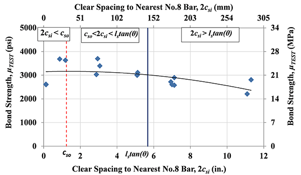
Figure 19. Graph. Effect of bar spacing: bond strength µTEST versus 2csi for specimens in Set 1. The cso is constant.
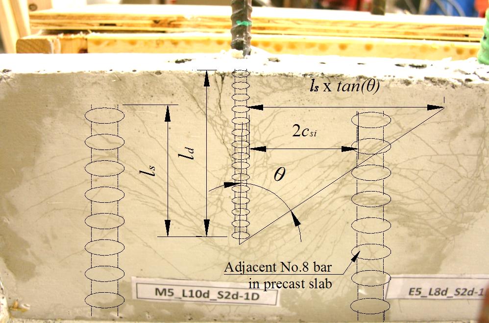
Figure 20. Illustration. Geometrical demonstration of lstan(θ) and 2csi.
The bond strength is plotted versus 2csi in Figure 19, and as shown, only a very limited number of specimens fell in the range of 2csi< cso. When the testing bar was in contact with extended No.8 bars (2csi near to zero), it expressed less bond strength than those with larger spacing. The bond strength for the two contact lap splice specimens was 2575 and 2576 psi (17.8 and 17.8 MPa), respectively. For the specimens with bar spacing greater than zero but less than lstan(θ), the observed bond strength was about the same, close to or greater than 3000 psi (20.7 MPa). Note that, other than the contact lap splice, the least bar spacing (center-to-center) that was tested in the study was 2 in. (5.1 cm), which is approximately 2db bar clear spacing. When the testing bar was placed further than lstan(θ) away from the adjacent No. 8 bars, the bond strength decreased, with an average bond stress of 2583 psi (17.8 MPa) for the six specimens in Set 1.
The similar trend was also observed in the other three sets of specimens. The bond strength versus bar clear spacing curve for specimens in Sets 2, 3, and 4 are presented in Figure 21, Figure 22, and Figure 23, respectively. The specimens in Set 2 had similar design as those in Set 1, except that the side cover was increased from 2db to 3.5db. The specimens in Set 3 had a nominal embedment length of 6db and side cover of 2db and all tests were conducted at 7 days after UHPC casting, with an average compressive strength of 19.2 ksi (132 MPa). While A1035 No. 5 bars were used in Sets 1, 2 and 3, A1035 No. 4 bars were used in Set 4, with an embedment length of 6db and side cover of 3.5db. The bar spacing for specimens in Sets 2, 3, and 4 was varied. The trend that can be noted from these series of tests is that specimens with the bar spacing between 2db and lstan(θ) have higher bond strength than those with a contact lap splice and those with bar spacing bigger than lstan(θ). The bar spacing of 2db is the least clear spacing, other than contact lap splice, investigated in this study.
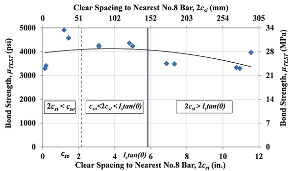
Figure 21. Graph. Effect of bar spacing: bond strength µTEST versus 2csi for specimens in Set 2. The cso is constant.
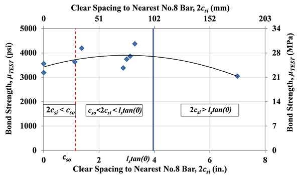
Figure 22. Graph. Effect of bar spacing: bond strength µTEST versus 2csi for specimens in Set 3. The cso is constant.
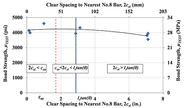
Figure 23. Graph. Effect of bar spacing: bond strength µTEST versus 2csi for specimens in Set 4. The cso is constant.
The average bond strength for specimens with bar spacing between 2db and lstan(θ) was compared with those with bar spacing out of the range and the results are presented in Table 8. As shown in Table 8, the reduction of bond strength is over twenty percent in most cases. The decrease on bond stress for contacted lap splice specimens is probably due to decreased contact area between the reinforcing bar and UHPC materials, especially considering the dispersion of the fiber reinforcement into the spaces near closely spaced bars, which is needed to locally enhance the mechanical resistance of the UHPC. This is contrary to early studies in normal non-fiber reinforced concrete (23,24,25), where it was concluded that tied spliced (zero spacing) bars had similar or even better bond strength than non-contact lap splices. When the bar clear spacing is larger than lstan(θ), the induced diagonal cracks from the pullout force will not intersect with the adjacent bar and the bond strength is primarily dependent on the performance of the individual bar in the UHPC.
Table 8. Bond strength reduction for bar clear spacing out of the range of 2db < 2csi < lstan(θ).
| Bar clear spacing | 2db< 2csi<lstan(θ) | Contact lap splice | 2csi>lstan(θ) | ||
|---|---|---|---|---|---|
| Avg. µTEST, psi | Avg. µTEST, psi | Reduction, % | Avg. µTEST, psi | Reduction, % | |
| Set 1 | 3279 | 2575 | 21 | 2583 | 21 |
| Set 2 | 4376 | 3309 | 24 | 3472 | 21 |
| Set 3 | 3815 | 3324 | 13 | 2999 | 21 |
| Set 4 | NA | 4154 | NA | 3842 | NA |
The effect of UHPC compressive strength on bond strength is analyzed in this section. For the UHPC materials tested in this study, the average compressive strength was 13.5 ksi (93 MPa) at one day, 17.0 ksi (117 MPa) at three days, 19.4 ksi (133 MPa) at seven days, and 21.3 ksi (147 MPa) at 14 days.
A total of 41 specimens were included and all specimens were tested with A1035 No.5 bars. The details of all specimens are presented in Table 9. The specimens were grouped into three sets based on side cover, and specimens with different embedment lengths were included in the same set. The specimens were grouped so that the specimens in each set can be either directly compared to those with the same embedment length or indirectly compared by comparing the bond strength µTEST for all specimens. As shown in Table 9, in Set 1 a side cover of 2db with a constant bar spacing [center to center 4 in. (10 cm)] was used; specimens with embedment length of 4db, 6db, 8db, 10db, and 12db were tested at either 1, 3, or 7 days after casting. Set 2 specimens had a side cover of 3db with embedment length of either 6db or 6.7db and they were tested at either 1 or 7 days. Similarly, Set 3 specimens had a side cover of 3.5db and embedment length of either 6db or 8db; they were tested at either 1 or 7 days.
As expected, an increase in the compressive strength increases the bond strength, as shown in Table 9. For example, for specimens with embedment length of 6db and side cover of 2db in Set 1, the average bar stress at bond failure increased from 81 to 89 ksi (558 to 613 MPa) when the compressive strength increased from 13.5 to 19.5 ksi (93 to 135 MPa). In a separate comparison, when the embedment length was 12db with the UHPC compressive strength at 13.4 ksi (92 MPa), the average bar stress at bond failure was 128 ksi (883 MPa); increasing the UHPC compressive strength to 19.5 ksi (135 MPa) resulted in bar rupture, with bar stress over 160 ksi (1103 MPa) before bond failure.
The relationship between the bond strength and UHPC compressive strength was also assessed. Traditionally, the effect of concrete properties on bond strength is represented by the square root of the compressive strength ƒ’c1/2 , which is related to tensile strength of the concrete. This representation is normally limited to a maximum concrete strength of 8000 psi (55 MPa) (ACI 408 R-03) (17). The relationship between the bond strength and the UHPC compressive strength is evaluated here. The bond strength is plotted versus f’c and ƒ’c1/2 for specimens in Sets 1, 2, and 3 in Figure 24, Figure 25, and Figure 26, respectively. As shown in the figures, the correlation coefficient (R2) values for all three sets of tests are low, no matter it is between µTEST and ƒ’c or between µTEST and ƒ’c1/2. Since the UHPC material investigated is both high strength and fiber reinforced, other material properties besides compressive strength should be involved in the evaluating of bond strength.
Table 9. Test specimens - effect of UHPC compressive strength
| Batch ID | f'c, ksi | ld, in. | ls, in. | cso, in. | csi, in. | fs,max, ksi | s1, in. | fs,crack, ksi | µTEST, ksi | |
|---|---|---|---|---|---|---|---|---|---|---|
| Set 1 | M5-L4d-S2d-Sp4-1D-B5S2 | 13.9 | 2.6 | 1.6 | 1.2 | 1.5 | 43 | 0.033 | NA | 2640 |
| M5-L4d-S2d-Sp4-1D-B5S2 | 13.9 | 2.7 | 1.7 | 1.2 | 1.6 | 49 | 0.020 | NA | 2828 | |
| M5-L4d-S2d-Sp4-7D-B1S1 | 19.9 | 2.4 | 1.4 | 1.2 | 1.5 | 67 | 0.036 | NA | 4449 | |
| M5-L4d-S2d-Sp4-7D-B3S1 | 19.5 | 2.4 | 2.2 | 1.2 | 1.4 | 59 | 0.041 | 40 | 3781 | |
| M5-L6d-S2d-Sp4-1D-B3S1 | 13.2 | 3.7 | 3.4 | 1.2 | 1.6 | 77 | 0.042 | 45 | 3269 | |
| M5-L6d-S2d-Sp4-1D-B4S2 | 13.6 | 3.8 | 3.6 | 1.2 | 1.4 | 84 | 0.053 | 42 | 3430 | |
| M5-L6d-S2d-Sp4-1D-B4S2 | 13.6 | 3.8 | 2.8 | 1.3 | 1.4 | 82 | 0.053 | 58 | 3363 | |
| M5-L6d-S2d-Sp4-7D-B1S1 | 19.9 | 3.3 | 2.3 | 1.4 | 1.6 | 91 | 0.072 | NA | 4326 | |
| M5-L6d-S2d-Sp4-7D-B3S1 | 19.5 | 3.8 | 3.5 | 1.2 | 1.6 | 91 | 0.068 | 52 | 3812 | |
| M5-L6d-S2d-Sp4-7D-B3S1 | 19.5 | 3.8 | 2.8 | 1.2 | 1.5 | 90 | 0.052 | 58 | 3695 | |
| M5-L6d-S2d-Sp4-7D-B4S2 | 19.2 | 3.9 | 2.9 | 1.1 | 1.4 | 83 | 0.047 | 65 | 3335 | |
| M5-L8d-S2d-Sp4-1D-B3S1 | 13.2 | 5.0 | 4.0 | 1.2 | 1.4 | 96 | 0.065 | 58 | 2995 | |
| M5-L8d-S2d-Sp4-1D-B6S3 | 13.9 | 4.6 | 3.6 | 1.2 | 1.5 | 108 | 0.057 | 68 | 3649 | |
| M5-L8d-S2d-Sp4-1D-B8S4 | 13.8 | 4.9 | 3.9 | 1.1 | 1.5 | 106 | 0.050 | NA | 3346 | |
| M5-L8d-S2d-Sp4-3D-B1S1 | 17.3 | 4.8 | 3.8 | 1.4 | 1.3 | 108 | 0.075 | NA | 3506 | |
| M5-L8d-S2d-Sp4-3D-B9S4 | 16.6 | 5.2 | 4.2 | 1.3 | 1.4 | 111 | 0.066 | NA | 3330 | |
| M5-L8d-S2d-Sp4-7D-B3S1 | 19.5 | 5.1 | 4.1 | 1.2 | 1.6 | 114 | 0.059 | 58 | 3515 | |
| M5-L8d-S2d-Sp4-7D-B9S4 | 18.8 | 5.0 | 4.0 | 1.1 | 1.5 | 127 | 0.070 | NA | 3979 | |
| M5-L10d-S2d-Sp4-1D-B6S3 | 13.9 | 6.3 | 5.3 | 1.2 | 1.5 | 144 | 0.082 | 77 | 3602 | |
| M5-L10d-S2d-Sp4-1D-B9S4 | 13.7 | 6.3 | 5.3 | 1.2 | 1.5 | 132 | 0.076 | 65 | 3276 | |
| M5-L10d-S2d-Sp4-7D-B3S1 | 19.5 | 6.2 | 5.2 | 1.2 | 1.5 | 145 | 0.091 | 74 | 3653 | |
| M5-L10d-S2d-Sp4-7D-B9S4 | 18.8 | 6.1 | 5.1 | 1.1 | 1.6 | 154 | 0.100 | NA | 3935 | |
| M5-L10d-S2d-Sp4-7D-B9S4 | 18.8 | 6.1 | 5.1 | 1.2 | 1.5 | 153 | 0.115 | NA | 3944 | |
| M5-L12d-S2d-Sp4-1D-B2S1 | 13.4 | 7.6 | 6.6 | 1.2 | 1.5 | 127 | 0.103 | 106 | 2603 | |
| M5-L12d-S2d-Sp4-1D-B2S2 | 13.4 | 7.6 | 6.6 | 1.3 | 1.6 | 129 | 0.090 | 97 | 2645 | |
| M5-L12d-S2d-Sp4-7D-B2S1 | 19.5 | 7.6 | 6.6 | 1.2 | 1.4 | bar rupture (>160 ksi) | 0.135 | 87 | NA | |
| M5-L12d-S2d-Sp4-7D-B2S2 | 19.5 | 7.5 | 6.5 | 1.4 | 1.5 | bar rupture (>160 ksi) | 0.152 | NA | NA | |
| Set 2 | M5-L6d-S3d-Sp4-1D-B10S4 | 13.9 | 3.4 | 2.4 | 1.8 | 1.5 | 85 | 0.037 | NA | 3863 |
| M5-L6d-S3d-Sp4-1D-B10S4 | 13.9 | 3.8 | 2.8 | 1.8 | 1.5 | 84 | 0.051 | NA | 3494 | |
| M5-L6d-S3d-Sp4-7D-B10S4 | 19.6 | 3.9 | 2.9 | 1.8 | 1.7 | 118 | 0.058 | NA | 4673 | |
| M5-L6d-S3d-Sp4-7D-B10S4 | 19.6 | 3.9 | 2.9 | 1.9 | 1.6 | 111 | 0.055 | NA | 4486 | |
| M5-L6.7d-S3d-Sp4-1D-B10S4 | 13.9 | 4.2 | 3.2 | 1.9 | 1.6 | 103 | 0.045 | NA | 3800 | |
| M5-L6.7d-S3d-Sp4-1D-B10S4 | 13.9 | 4.1 | 3.1 | 1.8 | 1.5 | 115 | 0.060 | NA | 4365 | |
| M5-L6.7d-S3d-Sp4-7D-B10S4 | 19.6 | 4.3 | 3.3 | 1.9 | 1.6 | 130 | 0.061 | NA | 4775 | |
| M5-L6.7d-S3d-Sp4-7D-B10S4 | 19.6 | 4.2 | 3.2 | 1.9 | 1.5 | 117 | 0.050 | NA | 4359 | |
| Set 3 | M5-L6d-S3.5d-Sp4-1D-B4S2 | 13.6 | 3.9 | 3.6 | 2.2 | 1.6 | 96 | 0.043 | NA | 3884 |
| M5-L6d-S3.5d-Sp4-1D-B4S2 | 13.6 | 3.8 | 2.8 | 2.2 | 1.6 | 90 | 0.045 | 79 | 3707 | |
| M5-L6d-S3.5d-Sp4-7D-B4S2 | 19.2 | 3.8 | 3.5 | 2.3 | 1.6 | 117 | 0.051 | 106 | 4876 | |
| M5-L6d-S3.5d-Sp4-7D-B4S2 | 19.2 | 3.8 | 2.8 | 2.3 | 1.6 | 124 | 0.061 | 106 | 5148 | |
| M5-L8d-S3.5d-Sp4-1D-B4S2 | 13.6 | 5.1 | 4.1 | 2.4 | 1.6 | 136 | 0.080 | 65 | 4208 | |
| M5-L8d-S3.5d-Sp4-1D-B7S3 | 13.5 | 5.1 | 4.1 | 2.1 | 1.6 | 137 | 0.068 | 97 | 4168 | |
| M5-L8d-S3.5d-Sp4-1D-B7S3 | 13.5 | 5.1 | 4.1 | 1.8 | 1.5 | 113 | 0.054 | 100 | 3477 | |
| M5-L8d-S3.5d-Sp4-7D-B4S2 | 19.2 | 5.0 | 4.0 | 2.3 | 1.6 | 145 | 0.096 | 87 | 4521 |
Note: For explanation of the specimen ID and each parameter, see note for Table 4 . 1 ksi = 6.895 MPa; 1 in. = 2.54 cm.
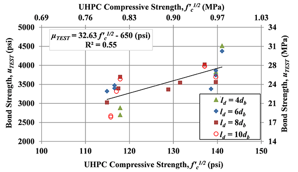
(b)
Figure 24. Graph. Effect of UHPC compressive strength: bond (a) uTEST versus ƒ'c and (b) uTEST versus ƒ’c1/2 for specimens in Set 1.
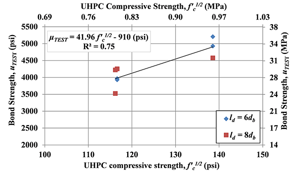
(b)
Figure 25. Graph. Effect of UHPC compressive strength: (a) uTEST versus ƒ'c and (b) uTEST versus ƒ’c1/2 for specimens in Set 2.
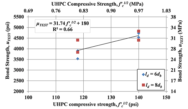
(b)
Figure 26. Graph. Effect of UHPC compressive strength: (a) uTEST versus ƒ'c and (b) uTEST versus ƒ’c1/2 for specimens in Set 3.
The majority of the tests in the study were conducted with A1035 No. 5 bar to serve as the baseline. In this section, the effect of bar size on bond strength is evaluated. Tests on A1035 No. 4, No. 5 and No. 7 bar were used in this analysis.
With the consideration that the design (development length, concrete cover, and bar spacing) is often defined in terms of bar diameter (db) in design codes, the embedment length and confinement used for different size bar will also be based on individual bar diameter in this section. For example, No. 4 bar with 2db side cover, which is 1 in. (2.5 cm), will be compared with the No. 5 bar with 2db side cover, which is 1.25 in. (3.2 cm), and they are considered to have the same side cover. Also as discussed previously, specimens with the bar spacing between 2db and lstan(θ) are recognized as demonstrating similar performance. All specimens in this section had bar spacing in this range and the effect of bar spacing is assumed to be minimal and will be neglected in this analysis.
A total of 27 tests were included in this section, divided into two sets as shown in Table 10. Set 1 included specimens with No. 5 and No. 4 bars and Set 2 included specimens with No. 5 and No. 7 bars. Specimens in each set had the same design for side cover and had varied embedment lengths. Specimens in each set can be either directly compared among those with the same design of embedment length or compared as a whole by comparing the bond strength uTEST, which included the embedment length in the calculation. All specimens were tested at one day after UHPC casting to ensure a similar compressive strength.
A direct comparison between the specimens with the same design reveals that, in general, higher bar stress was developed for smaller bars at bond failure. For example, for the specimen with No. 4 bar embedded 8db (specimen ID M4-L8d-S3.5d-Sp4-1D-B9S3) in Set 1, the bar stress at bond failure was 147 ksi (1014 MPa), higher than the 136 and 137 ksi (938 and 945 MPa) for the two specimens with No. 5 bars (specimen ID M5-L8d-S3.5d-Sp4-1D-B4S2 and M5-L8d-S3.5d-Sp4-1D-B7S3). Similarly, for the five specimens with No.7 bars embedded 8db in Set 2, the bar stress at bond failure ranged from 81 to 109 ksi (558 to 752 MPa) with an average of 99 ksi (686 MPa), compared with 96 to 121 ksi (662 to 834 MPa) with an average of 107 ksi (741 MPa) for the corresponding specimens with No. 5 bars.
Table 10. Test specimens - effect of bar size.
| Batch ID | f'c, ksi | ld, in. | ls, in. | cso, in. | csi, in. | fs,max, ksi | s1, in. | fs,crack, ksi | µTEST, ksi | |
|---|---|---|---|---|---|---|---|---|---|---|
| Set 1 | M4-L8d-S3.5d-Sp4-1D-B9S3 | 13.7 | 4.1 | 3.1 | 1.7 | 1.5 | 147 | 0.073 | NA | 4460 |
| M5-L8d-S3.5d-Sp4-1D-B4S2 | 13.6 | 5.1 | 4.1 | 2.4 | 1.6 | 136 | 0.080 | 65 | 4208 | |
| M5-L8d-S3.5d-Sp4-1D-B7S3 | 13.5 | 5.1 | 4.1 | 2.1 | 1.6 | 137 | 0.068 | 97 | 4168 | |
| M4-L6d-S3.5d-Sp4-1D-B12S5 | 11.9 | 3.1 | 2.1 | 1.7 | 1.6 | 106 | 0.041 | NA | 4243 | |
| M4-L6d-S3.5d-Sp4-1D-B12S5 | 11.9 | 3.1 | 2.1 | 1.6 | 1.4 | 97 | 0.038 | NA | 3867 | |
| M5-L6d-S3.5d-Sp4-1D-B4S2 | 13.6 | 3.9 | 2.9 | 2.2 | 1.6 | 96 | 0.043 | NA | 3884 | |
| M5-L6d-S3.5d-Sp4-1D-B4S2 | 13.6 | 3.8 | 2.8 | 2.2 | 1.6 | 90 | 0.045 | 79 | 3707 | |
| M4-L10d-S3.5d-Sp4-1D-B9S3 | 13.7 | 5.2 | 4.2 | 1.7 | 1.6 | 156 | 0.105 | NA | 3757 | |
| M4-L10d-S3.5d-Sp4-1D-B9S3 | 13.7 | 5.2 | 4.2 | 1.7 | 1.6 | 165 | 0.144 | NA | 3978 | |
| M5-L10d-S3.5d-Sp4-1D-B4S2 | 13.6 | 6.3 | 5.3 | 2.2 | 1.6 | 155 | 0.108 | 90 | 3843 | |
| M5-L10d-S3.5d-Sp4-1D-B4S2 | 13.6 | 6.3 | 5.3 | 2.2 | 1.6 | 166 | 0.161 | 68 | 4116 | |
| M5-L10d-S3.5d-Sp4-1D-B4S2 | 13.6 | 6.3 | 5.3 | 2.3 | 1.6 | 158 | 0.099 | 125 | 3911 | |
| Set 2 | M7-L8d-S2d-Sp2-1D-B12S5 | 11.9 | 6.9 | 5.9 | 2.0 | 0.6 | 109 | 0.058 | NA | 3462 |
| M7-L8d-S2d-Sp6-1D-B12S5 | 11.9 | 6.8 | 5.8 | 1.9 | 2.4 | 81 | 0.068 | NA | 2609 | |
| M7-L8d-S2d-Sp6-1D-B12S5 | 11.9 | 7.0 | 6.0 | 1.9 | 2.1 | 122 | 0.111 | NA | 3824 | |
| M7-L8d-S2d-Sp6-1D-B12S5 | 11.9 | 7.0 | 6.0 | 1.9 | 2.5 | 92 | 0.080 | NA | 2875 | |
| M7-L8d-S2d-Sp4-1D-B8S3 | 13.8 | 7.2 | 6.2 | 1.7 | 1.5 | 93 | 0.036 | NA | 2823 | |
| M5-L8d-S2d-Sp4-1D-B3S1 | 13.2 | 5.0 | 4.0 | 1.2 | 1.4 | 96 | 0.065 | 58 | 2995 | |
| M5-L8d-S2d-Sp4-1D-B6S3 | 13.9 | 4.6 | 3.6 | 1.2 | 1.5 | 108 | 0.057 | 68 | 3649 | |
| M5-L8d-S2d-Sp4-1D-B8S4 | 13.8 | 4.9 | 3.9 | 1.1 | 1.5 | 106 | 0.050 | NA | 3346 | |
| M5-L8d-S2d-Sp4-1D-B9S4 | 13.7 | 5.3 | 4.3 | 1.2 | 1.4 | 121 | 0.065 | 77 | 3595 | |
| M7-L6d-S2d-Sp4-1D-B8S3 | 13.8 | 5.3 | 4.3 | 1.6 | 1.3 | 60 | 0.021 | NA | 2510 | |
| M7-L6d-S2d-Sp4-1D-B8S3 | 13.8 | 5.0 | 4.0 | 1.6 | 1.4 | 61 | 0.042 | NA | 2657 | |
| M5-L6d-S2d-Sp4-1D-B3S1 | 13.2 | 3.7 | 3.4 | 1.2 | 1.6 | 77 | 0.042 | 45 | 3269 | |
| M5-L6d-S2d-Sp4-1D-B3S1 | 13.2 | 3.8 | 2.8 | 1.3 | 1.6 | 70 | 0.058 | 55 | 2876 | |
| M5-L6d-S2d-Sp4-1D-B4S2 | 13.6 | 3.8 | 3.6 | 1.2 | 1.4 | 84 | 0.053 | 42 | 3430 | |
| M5-L6d-S2d-Sp4-1D-B4S2 | 13.6 | 3.8 | 2.8 | 1.3 | 1.4 | 82 | 0.053 | 58 | 3363 |
Note: For explanation of the specimen ID and each parameter, see note for Table 4 . 1 ksi = 6.895 MPa; 1 in. = 2.54 cm.
The bond stress at bond failure was also calculated for each specimen and is presented in Table 10. The average bond stress for all No. 4 and No. 5 bars in Set 1 and for all No. 7 and No. 5 bars in Set 2 were compared in Figure 27. In addition to the average values of bond strength, the figure also shows the maximum and minimum values for the included specimens and the number of tests conducted. As shown in Figure 27, No. 4 bars had slightly higher average bond strength than the No. 5 bars in Set 1, and No. 5 bars had higher average bond strength than the No. 7 bars in Set 2. Note that all the comparisons are made between specimens with a similar design which is based on the individual bar diameter. With these conditions, the tests results indicated that for bars with larger diameter, the bond strength decreased and a longer embedment length should considered.
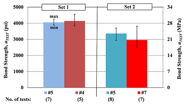
Figure 27. Chart. Bond strength versus bar size.
As demonstrated in previous sections, a reinforcing bar embedded only 6db in UHPC (with appropriate cover) can achieve a bar stress over 70 ksi (483 MPa) before bond failure. To minimize the effect of reinforcing bar yielding on bond strength when other factors were evaluated, the majority of the tests in the study were conducted using A1035 Grade 120 bar. The effect of bar type and the effect of bar yielding prior to bond failure are evaluated in this section.
A total of 46 tests are included in this section and the tests were grouped into six sets based on embedment length as shown in Table 11. Each set had three types of reinforcing bar, uncoated, epoxy coated, and A1035, except for Set 6 having only uncoated and A1035 bar. The six sets are presented in an order from low bond strength to high bond strength. In each set, the bond strength of different types of bar can be compared directly with the fact they had the same design. The reinforcing bar properties, including yield and tensile strengths and relative rib area, can be found in Table 2 and the rib pattern can be found in Figure 2. As the relative rib area is one of the main factors when looking at different types reinforcing bar, it should be noted that the No.5 uncoated, epoxy coated, and A1035 bar used in this study had similar relative rib areas, with values of 0.085, 0.083 and 0.088, respectively.
The average bar stress at bond failure for each type of bar in each set is presented in Figure 28. The maximum and minimum values for included specimens in each group are also presented. As shown in Figure 28, for specimens with ultimate bar stress at bond failure below or close to the yield strength of the uncoated bar (Sets 1 and 2), the A1035 and uncoated bar had similar bond strength. When the bar stress at bond failure was greater than the yield strength of the uncoated bar, the A1035 bar had higher ultimate bar stress than the corresponding uncoated bar. In all cases, the epoxy coated bar had lower ultimate bar stress than the corresponding uncoated and A1035 bar. It is reasonable to predict the bond performance of the Grade 60 uncoated bar based on the tests of A1035 bar, up to at least the yield strength of the Grade 60 uncoated bar; beyond the yield, it is important to realize the fact that bars that yielded before bond failures produced average bond stress lower than A1035 bars in similar test specimens. The epoxy coated bar had lower bond strength than uncoated bar.
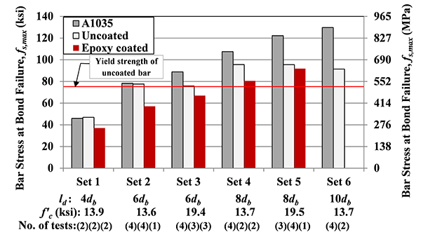
Figure 28. Chart. Average bar stress at bond failure for different types of reinforcing bar.
Table 11. Test specimens - effect of bar type.
| Batch ID | f'c, ksi | ld, in. | ls, in. | cso, in. | csi, in. | fs,max, ksi | s1, in. | fs,crack, ksi | µTEST, ksi | |
|---|---|---|---|---|---|---|---|---|---|---|
| Set 1 | B5-L4d-S2d-Sp4-1D-B5S2 | 13.9 | 2.6 | 1.6 | 1.1 | 1.6 | 46 | 0.032 | NA | 2719 |
| B5-L4d-S2d-Sp4-1D-B5S2 | 13.9 | 2.5 | 1.5 | 1.2 | 1.5 | 48 | 0.033 | NA | 3014 | |
| E5-L4d-S2d-Sp4-1D-B5S2 | 13.9 | 2.6 | 1.6 | 1.0 | 1.5 | 38 | 0.051 | NA | 2233 | |
| E5-L4d-S2d-Sp4-1D-B5S2 | 13.9 | 2.6 | 1.6 | 1.2 | 1.5 | 37 | 0.045 | NA | 2177 | |
| M5-L4d-S2d-Sp4-1D-B5S2 | 13.9 | 2.6 | 1.6 | 1.2 | 1.5 | 43 | 0.033 | NA | 2640 | |
| M5-L4d-S2d-Sp4-1D-B5S2 | 13.9 | 2.7 | 1.7 | 1.2 | 1.6 | 49 | 0.020 | NA | 2828 | |
| Set 2 | B5-L6d-S2d-Sp4-1D-B2S1 | 13.4 | 3.8 | 2.8 | 1.1 | 1.5 | 82 | 0.091 | NA | 3368 |
| B5-L6d-S2d-Sp4-1D-B4S2 | 13.6 | 3.8 | 2.8 | 1.3 | 1.4 | 76 | 0.087 | 44 | 3156 | |
| B5-L6d-S2d-Sp4-1D-B6S3 | 13.9 | 3.4 | 2.4 | 1.2 | 1.3 | 70 | 0.055 | 65 | 3222 | |
| B5-L6d-S2d-Sp4-1D-B6S3 | 13.9 | 3.8 | 2.8 | 1.1 | 1.4 | 83 | 0.090 | 55 | 3393 | |
| E5-L6d-S2d-Sp4-1D-B4S2 | 13.6 | 3.8 | 2.8 | 1.2 | 1.4 | 57 | 0.055 | 42 | 2378 | |
| M5-L6d-S2d-Sp4-1D-B3S1 | 13.2 | 3.7 | 3.4 | 1.2 | 1.6 | 77 | 0.042 | 45 | 3269 | |
| M5-L6d-S2d-Sp4-1D-B3S1 | 13.2 | 3.8 | 2.8 | 1.3 | 1.6 | 70 | 0.058 | 55 | 2876 | |
| M5-L6d-S2d-Sp4-1D-B4S2 | 13.6 | 3.8 | 3.6 | 1.2 | 1.4 | 84 | 0.053 | 42 | 3430 | |
| M5-L6d-S2d-Sp4-1D-B4S2 | 13.6 | 3.8 | 2.8 | 1.3 | 1.4 | 82 | 0.053 | 58 | 3363 | |
| Set 3 | B5-L6d-S2d-Sp4-7D-B2S2 | 19.5 | 3.9 | 2.9 | 1.3 | 1.6 | 73 | 0.067 | 65 | 2901 |
| B5-L6d-S2d-Sp4-7D-B4S2 | 19.2 | 3.8 | 2.8 | 1.3 | 1.4 | 81 | 0.101 | 47 | 3337 | |
| B5-L6d-S2d-Sp4-7D-B5S2 | 18.9 | 3.8 | 2.8 | 1.2 | 1.5 | 73 | 0.066 | 52 | 3037 | |
| E5-L6d-S2d-Sp4-7D-B1S1 | 19.9 | 3.6 | 2.6 | 1.3 | 1.5 | 71 | 0.059 | NA | 3112 | |
| E5-L6d-S2d-Sp4-7D-B4S2 | 19.2 | 3.8 | 2.8 | 1.3 | 1.4 | 64 | 0.031 | NA | 2651 | |
| E5-L6d-S2d-Sp4-7D-B5S2 | 18.9 | 3.8 | 2.8 | 1.1 | 1.6 | 66 | 0.063 | 58 | 2742 | |
| M5-L6d-S2d-Sp4-7D-B1S1 | 19.9 | 3.3 | 2.3 | 1.4 | 1.6 | 91 | 0.072 | NA | 4326 | |
| M5-L6d-S2d-Sp4-7D-B3S1 | 19.5 | 3.8 | 3.5 | 1.2 | 1.6 | 91 | 0.068 | 52 | 3812 | |
| M5-L6d-S2d-Sp4-7D-B3S1 | 19.5 | 3.8 | 2.8 | 1.2 | 1.5 | 90 | 0.052 | 58 | 3695 | |
| M5-L6d-S2d-Sp4-7D-B4S2 | 19.2 | 3.9 | 2.9 | 1.1 | 1.4 | 83 | 0.047 | 65 | 3335 | |
Set 4 |
B5-L8d-S2d-Sp4-1D-B2S1 | 13.4 | 5.3 | 4.3 | 1.2 | 1.5 | 96 | 0.205 | 77 | 2857 |
| B5-L8d-S2d-Sp4-1D-B2S2 | 13.4 | 5.1 | 4.1 | 1.4 | 1.5 | 95 | 0.215 | NA | 2936 | |
| E5-L8d-S2d-Sp4-1D-B6S3 | 13.9 | 4.7 | 3.7 | 1.2 | 1.4 | 78 | 0.090 | 58 | 2612 | |
| E5-L8d-S2d-Sp4-1D-B6S3 | 13.9 | 5.1 | 4.1 | 1.2 | 1.3 | 83 | 0.106 | 55 | 2553 | |
| M5-L8d-S2d-Sp4-1D-B3S1 | 13.2 | 5.0 | 4.0 | 1.2 | 1.4 | 96 | 0.065 | 58 | 2995 | |
| M5-L8d-S2d-Sp4-1D-B6S3 | 13.9 | 4.6 | 3.6 | 1.2 | 1.5 | 108 | 0.057 | 68 | 3649 | |
| M5-L8d-S2d-Sp4-1D-B8S4 | 13.8 | 4.9 | 3.9 | 1.1 | 1.5 | 106 | 0.050 | NA | 3346 | |
| M5-L8d-S2d-Sp4-1D-B9S4 | 13.7 | 5.3 | 4.3 | 1.2 | 1.4 | 121 | 0.065 | 77 | 3595 | |
| Set 5 | B5-L8d-S2d-Sp4-7D-B2S1 | 19.5 | 5.1 | 4.1 | 1.1 | 1.5 | 94 | 0.162 | 68 | 2913 |
| B5-L8d-S2d-Sp4-7D-B2S1 | 19.5 | 5.1 | 4.1 | 1.1 | 1.5 | 95 | 0.078 | NA | 2922 | |
| B5-L8d-S2d-Sp4-7D-B2S2 | 19.5 | 5.1 | 4.1 | 1.4 | 1.6 | 96 | 0.184 | 65 | 2933 | |
| B5-L8d-S2d-Sp4-7D-B2S2 | 19.5 | 5.1 | 4.1 | 1.4 | 1.6 | 97 | 0.075 | NA | 2947 | |
| E5-L8d-S2d-Sp4-7D-B1S1 | 19.9 | 4.9 | 3.9 | 1.5 | 1.6 | 92 | 0.167 | NA | 2935 | |
| M5-L8d-S2d-Sp4-7D-B1S1 | 19.9 | 4.8 | 3.8 | 1.1 | 1.4 | 125 | 0.087 | NA | 4069 | |
| M5-L8d-S2d-Sp4-7D-B3S1 | 19.5 | 5.1 | 4.1 | 1.2 | 1.6 | 114 | 0.059 | 58 | 3515 | |
| M5-L8d-S2d-Sp4-7D-B9S4 | 18.8 | 5.0 | 4.0 | 1.1 | 1.5 | 127 | 0.070 | NA | 3979 | |
| Set 6 | B5-L10d-S2d-Sp4-1D-B2S1 | 13.4 | 6.3 | 5.3 | 1.2 | 1.6 | 94 | 0.128 | 71 | 2335 |
| B5-L10d-S2d-Sp4-1D-B2S2 | 13.4 | 6.3 | 5.3 | 1.4 | 1.5 | 88 | 0.167 | NA | 2189 | |
| M5-L10d-S2d-Sp4-1D-B6S3 | 13.9 | 6.3 | 5.3 | 1.2 | 1.5 | 144 | 0.082 | 77 | 3602 | |
| M5-L10d-S2d-Sp4-1D-B6S3 | 13.9 | 6.4 | 5.4 | 1.2 | 1.4 | 113 | 0.075 | 61 | 2760 | |
| M5-L10d-S2d-Sp4-1D-B9S4 | 13.7 | 6.3 | 5.3 | 1.2 | 1.5 | 132 | 0.076 | 65 | 3276 |
Note: For explanation of the specimen ID and each parameter, see note for Table 4. 1 ksi = 6.895 MPa; 1 in. = 2.54 cm
The average bond stress µTEST for each type of reinforcing bar in each set is calculated and presented in Table 12, as well as the bond stress reduction between different reinforcing bar. As shown in Table 12, the uncoated bars in Sets 1 and 2 had about the same bond stress as A1035 bars, with a slight difference of 4.9% and 1.6%, respectively; when the maximum bar stress at bond failure exceeded the yield strength of the uncoated bar, as those in Sets 3, 4, 5, and 6, the A1035 bars had much higher ultimate bond stress than that of uncoated bars, ranging from 14.7% to 29.6% with an average of 21.7% higher. Another noted trend is that the reduction on bond strength due to the yielding of uncoated bar is amplified as the ultimate bar stress at bond failure increases. The reduction on bond stress were 18.5%, 14.7%, 24.0%, and 29.6% following the order of Sets 3, 4, 5, and 6, which are grouped in the order of increasing ultimate bar stress at bond failure.
The bond stress reduction of epoxy coated bar compared with uncoated bar is also presented in Table 12. The reductions were 23.1% and 27.6% in Sets 1 and 2 where the ultimate bar stress at bond failure is below or close to yield strength of the uncoated bar. The difference seemed to be minimized when there is a sufficient embedment length that the bar yielded before bond failure, with 8.3% and 10.8% reduction in Sets 3 and 4 and almost no reductions in Set 5.
Table 12. Bond stress reduction between different types of reinforcing bar.
| Average µTEST, psi | Reduction, % | ||||
|---|---|---|---|---|---|
| A1035 | Uncoated | Epoxy | (A1035-Uncoated)/A1035 | (Uncoated-Epoxy)/Uncoated | |
| Set 1 | 2734 | 2867 | 2205 | -4.9 | 23.1 |
| Set 2 | 3235 | 3285 | 2378 | -1.6 | 27.6 |
| Set 3 | 3792 | 3092 | 2835 | 18.5 | 8.3 |
| Set 4 | 3396 | 2896 | 2583 | 14.7 | 10.8 |
| Set 5 | 3854 | 2929 | 2935 | 24.0 | -0.2 |
| Set 6 | 3213 | 2262 | - | 29.6 | - |