U.S. Department of Transportation
Federal Highway Administration
1200 New Jersey Avenue, SE
Washington, DC 20590
202-366-4000
Federal Highway Administration Research and Technology
Coordinating, Developing, and Delivering Highway Transportation Innovations
| REPORT |
| This report is an archived publication and may contain dated technical, contact, and link information |
|
| Publication Number: FHWA-HRT-13-088 Date: May 2014 |
Publication Number: FHWA-HRT-13-088 Date: May 2014 |
For each case, through visual observation of the photographs, different pieces of information were collected and stored as variables. This section provides the general procedure of how these variables were collected and a brief explanation of the variables used. It also provides some statistics that summarize the data collected in those variables.
The NMVCCS database groups all of its information by crash case. Each crash case has a narrative that explains how the crash happened and its possible causes. The analyst must review this narrative and answer the following questions to obtain a general idea of how the crash happened:
The second and third questions are especially important to understand the location of the barrier and the shoulder that might have been involved in the crash. The location information is stored as variables, allowing readers to better understand how the crash happened by just consulting the information from the variables.
After answering the questions, the analyst must observe the crash photographs and try to draw all the necessary information from the photographs. The fourth question helps the analyst avoid missing other important aspects in the road. With this help and with an element of discretion, the analyst assumes that most of the characteristics of the roadway that appear in the photographs, such as contamination and surface anomalies, should be stored in the variables.
The fifth question is directly stored in the variables. There is a variable labeled “Reported Precipitation” that is used to indicate the precipitation conditions at the moment of the crash.
Lastly, the analyst must determine if the photograph was taken at the moment of the crash or after the crash. Information such as contamination and the damage caused to the road should only be used from photographs taken at the moment of the crash. However, geometric characteristics can be obtained from photographs that happened after the crash. While NMVCCS provides some indication on when the photograph was taken, the analyst must make that determination, either on-scene or sometime after the crash. Although NMVCCS was conceived as on-scene data, some crash scenes might have been complicated by roadway traffic, in the absence of closure, limited closure time, or some such access impediment. In these cases, the researcher might have opted to review less time-critical aspects of the crash scene within hours of the crash once crash victims had been transported and vehicles towed from scene.
After following the approach, the analyst must describe the crash using the elements in table 6 and store the corresponding information.
The variables used to capture the information are classified into four groups according to what part of the road they describe: shoulder; roadway, barrier, and precipitation. They can also be classified into four groups according to the type of technical expertise needed to identify the information: pavement characteristics and contamination, geometric characteristics, damage caused, and precipitation. Most of the variables contain information associated to pre-specified attributes. The variables are explained in table 6.
| Part of the Road Described | Type of Information | # | Variable | Attributes | Observations |
|---|---|---|---|---|---|
| Shoulder | Geometry and physical elements | 1 | Location of the first shoulder involved |
|
“No shoulder involved” indicates that either the road has no shoulders or the vehicle did not leave the roadway during the crash. |
| 2 | Representative paved shoulder width |
|
The observation of the first variable also applies here. “Unknown location of first shoulder involved” should be selected if the value of the first variable is unknown. | ||
| 3 | Representative unpaved shoulder width |
|
The observations of the first and second variables apply here. | ||
| 4 | Major variations in paved shoulder width |
|
If the length in the second variable varies significantly, then the attribute “yes” should be selected here. The observations of the first and second variables apply here. | ||
| 5 | Major variations in unpaved shoulder width |
|
If the length in the third variable varies significantly, then the attribute “yes” should be selected here. The observations of the first and second variables apply here. | ||
| 6 | Roadway to paved shoulder drop-off |
|
The observations of the first and second variables apply here. | ||
| 7 | Presence of rumble strips |
|
The observations of the first and second variables apply here. | ||
| Pavement properties and contamination | 8 | Paved shoulder contamination |
|
The observations of the first and second variables apply here. | |
| Roadway | Geometry and physical elements | 9 | Pavement marking quality |
|
“No shoulder involved” indicates that either the road has no shoulders or the vehicle did not leave the roadway during the crash. |
| Pavement properties and contamination | 10 | Roadway pavement type |
|
||
| 11 | Apparent macro- texture |
|
Selecting “yes” requires having a very good photograph that effectively indicates that the road has an apparent macrotexture. | ||
| 12 | Rutting |
|
Selecting “yes” requires having a very good photograph that effectively indicates that the road has rutting. | ||
| 13 | Pavement contamination |
|
|||
| 14 | Gross pavement irregularities |
|
|||
| Barrier | Geometry and physical elements | 15 | Location of the first compromised barrier |
|
|
| 16 | Barrier type |
|
|||
| Barrier | Geometry and physical elements | 17 | Barrier end treatment type |
|
|
| 18 | Barrier post material |
|
|||
| 19 | Barrier block-out material |
|
|||
| 20 | Location of crash with respect to barrier |
|
|||
| 21 | Location of crash with respect to guardrail |
|
|||
| Damage caused | 22 | Ground to barrier face, measure-ment rods | N/A | Sometimes the people in charge of the photographs put a rod in front of the barrier. This rod has very visible marks that allow an approximate measurement of the distance between the ground and the beginning of the barrier face. | |
| 23 | Vertical barrier face, measure-ment rods | N/A | The observation of the 20th variable also applies here. | ||
| 24 | Horizontal damage barrier face, measure-ment rods | N/A | Although the expectation was that the people on the ground would put a rod for measuring this length on the damage, there were no photographs with this aiding rod. | ||
| 25 | Damage height from ground, measurement rods | N/A | The observation of the 21st variable also applies here. | ||
| 26 | Ground to barrier, Google Earth® | N/A | These variables are analogous to variables 20–23. Nonetheless, the measurement would not be taken by looking at a possible rod on the picture but by using Google Earth®. These variables were not actually used for the NMVCCS database but for another database (i.e., this was a flexible data entry meant to accommodate FARS as well as NMVCCS data as well). | ||
| 27 | Vertical barrier face, Google Earth® | N/A | |||
| 28 | Horizontal damage barrier face, Google Earth® | N/A | |||
| 29 | Damage height from ground, Google Earth® | N/A | |||
| 30 | Barrier condition |
|
|||
| Precipitation | Precipitation | 31 | Reported precipitation |
|
As mentioned previously, this variable did not come from the photographs but from the narrative of the NMVCCS database. |
| Note: Blank cells in observations denote an absence of special instructions for the referenced rubric. N/A = Not applicable. |
|||||
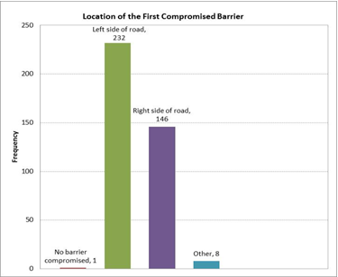
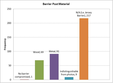
Figure 4 through figure 7 summarize some of the information captured in the variables in table 6. A comprehensive count of the information obtained can be found in appendix C.
 |
| Figure 4 . Graph. Attributes observed in the roadway to paved shoulder drop-off variable. |
 |
| Figure 5. Graph. Attributes observed in the roadway pavement type variable. |
 |
| Figure 6. Graph. Attributes observed in the location of the first compromised barrier variable. |
 |
| Figure 7. Graph. Attributes observed in the barrier post material variable. |
The previous section presented the procedure that should be followed to perform data extraction. This section illustrates that procedure followed by an explanation of how a catalog was used to identify different road elements in the case studies. These road elements include types of barriers and barrier end treatment types. Finally, cases in which difficulties were experienced are presented for capturing information from the photographs.
The example presented here corresponds to Case No. 2005079486822 from the NMVCCS database and follows the procedure explained in the previous section. The following variables are not mentioned in this example: paved shoulder contamination (8), apparent macrotexture (11), rutting (12), pavement contamination (13), and gross pavement irregularities (14). Those variables presented challenges for the analyst and are mentioned in the subsection “Challenging Aspects.”
The narrative presented in NMVCCS provides the following information (hereafter referred to as observations):
Observations 2, 3, and 5 provide an immediate answer to the question of which attributes assign to the following variables:
The photographs in figure 8 and figure 9 from the NMVCCS database indicate the following values to the variables corresponding to the shoulder:(4)
 |
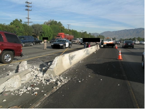
| Figure 8. Photo. First view of Case No. 2005079486822 showing the point of impact. |
 |
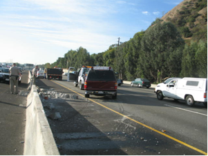
| Figure 9. Photo. Second view of Case No. 2005079486822 showing the point of impact. |
Variables 2 and 3 require the judgment of the analyst to indicate a length range for the shoulder. Figure 8 shows a pickup parked on the shoulder. Since a standard lane has a length of 12 ft, is assumed that the shoulder is longer than 8 ft. Variables 4 and 5 have a “yes” value if the shoulder varies considerably from the point where the vehicle hits the barrier to upstream. Because the photographs in figure 8 and figure 9 do not provide a good perspective for an answer to variable 4, the analyst needs to look at other photographs of the case, such as the photograph in figure 10 to confirm the “no” value. From figure 8 through figure 10, the analyst can confirm that the shoulder has no rumble strips (variable 6). They also allow the analyst to confirm that there is no drop-off between the roadway and the shoulder.
 |
| Figure 10. Photo. Case No. 2005079486822 look back from point of impact. |
Regarding characteristics on the roadway, figure 8 through figure 10 indicate the following values for the listed variables:
Regarding characteristics of the barrier, figure 8 through figure 10 indicate the following values for the listed variables:
It is important to note that variables 18 and 19 only apply to guardrails such as aesthetic timber barrier/wood guardrail, median barrier steel guardrail, Thrie beam, Thrie beam strong post, W-beam strong post, W-beam weak post, weak post box beam, and weathering steel (Corten®) guardrail. Variable 17 has a value of “outside the road segment of analysis” in this example because the crash did not happen at the end of a barrier.
An important question to ask is whether the vehicle had a hit along the barrier or at its end. This is answered through the photographs and allows determining the value for the location of crash with respect to the barrier. A similar variable is “location of crash with respect to guardrail.” This variable only looks at those barriers that are guardrails. In this specific example, those two variables have the following values:
Finally, the analyst should consider if there is information in the photographs that provides values for the following variables: ground to barrier face, measurement rods; vertical barrier face, measurement rods; horizontal damage barrier face, measurement rods; and damage height from ground, measurement rods. In the case analyzed in this example, there were no photographs that provide an estimate for these measurements. In some few cases, the people in charge of collecting the data put a rod next to the scene of the crash. A case with this information is provided in the subsection “Challenging Aspects.”
This section presents the original motivation for photographic data extraction feasibility and pilot studies with examples of different road elements. These road elements include the variables barrier type and barrier end treatment type. The analysts relied on a photograph catalog (shown in appendix A) to identify these road elements. Table 7 presents the road element for each example, while figure 11 through figure 16 show the corresponding photographs.
| Case No. | Barrier Type Element | Barrier End Treatment Type Element |
|---|---|---|
| 2005049602183 | W-beam strong post | Energy absorbing |
| 2005049602403 | High-tension cable guardrail systems | Outside the road segment of analysis |
| 2005012696122 | Thrie beam strong post | Non-energy absorbing (slotted rail terminal) |
| 2005082626081 | W-beam strong post | Impact attenuators |
 |
| Figure 11. Photo. Case No. 2005049602183 post-crash W-beam strong post (left) contrasted with comparative catalog image (right).(4,14) |
 |
| Figure 12. Photo. Case No. 2005049602183 post-crash W-beam strong post highlighting energy absorbing end treatment.(4,14) |
 |
| Figure 13. Photo. Case No. 2005049602403 post-crash high-tension cable guardrail systems (left) contrasted with comparative catalog image (right).(4,15) |
 |
| Figure 14. Photo. Case No. 2005012696122 post-crash Thrie beam strong post (left) contrasted with comparative catalog image (right).(4,16) |
 |
| Figure 15. Photo. Case No. 2005012696122 post-crash Thrie beam strong post (left) highlighting non-energy absorbing slotted rail terminal contrasted with comparative catalog image (right).(4,14) |
 |
| Figure 16. Photo. Case No. 2005082626081 post-crash impact attenuator (left) in advance of W-beam strong post (center) contrasted with comparative catalog image (right).(4,14) |
In response to colleagues studying pavement performance issues, this study was extended to identify variables related to pavement properties and contamination (see table 6). A pavement pilot study was initiated within the photographic data extraction pilot study. One of these variables was the macrotexture (11) of the pavement. The objective of this variable was to identify whether the road surface was in optimal condition (case in which the variable would have a “no” value) or whether it had features on the surface that highlighted some type of macrotexture. Figure 17 through figure 21 present photographs used to identify this variable. Experts in the field determined that these pictures are not of high enough quality to establish with assurance if the road surfaces present an identifiable macrotexture. For this reason, this variable was dropped and does not appear in the statistics of this study.
 |
| Figure 17. Photo. Photograph 1 used for identifying macrotexture in Case No. 2005012695244. |
 |
| Figure 18. Photo. Photograph 2 used for identifying macrotexture in Case No. 2005012695244. |
 |
| Figure 19. Photo. Photograph 3 used for identifying macrotexture in Case No. 2005012695244. |
 |
| Figure 20. Photo. Photograph 1 used for identifying macrotexture in Case No. 2007075702347. |
 |
| Figure 21. Photo. Photograph 2 used for identifying macrotexture in Case No. 2007075702347. |
Another variable that was included at the beginning of the study was rutting (variable 12). Figure 22 shows a probable case of rutting. After submitting this photograph to experts in the field, it was determined that it could not be used to determine rutting. As a result, this variable was dropped from the study. Due to similar reasons, the following other variables were dropped: paved shoulder contamination (8), pavement contamination (13), and gross pavement irregularities (14).
 |
| Figure 22. Photo. Photograph used for identifying rutting in Case No. 2007075702347. |
Finally, obtaining values for the following variables was challenging: ground to barrier face, measurement rods; vertical barrier face, measurement rods; horizontal damage barrier face, measurement rods; and damage height from ground, measurement rods. In very few cases, such as the one shown in figure 23, these measurements were possible to obtain.
 |
| Figure 23. Photo. Photograph from Case No. 2005073438121 in which measurements were obtained using rods. |
Although a great deal of new information has been identified through the study of NMVCCS images, several limiting factors must be acknowledged. First, the roadway departure problem comprised over half the crash fatalities.(1) However, the sample size is relatively small for researcher-investigated crashes benefitting from on-scene NMVCCS or near-crash time NASS CDS photography. FARS, while rich in data, provides limited details. This discussion section considers the data acquired from NMVCCS on-scene photography.
The supplementary dataset was envisioned to provide more roadside information than previously coded. The data were expected to have a uniform core of relevant variables and attributes. Finally, a systematic approach was to be devised through the feasibility and pilot studies to streamline data extraction.
Height of Barrier and Damage
The pilot study yielded unexpected results. Several roadside elements were highlighted by measurement rods that were originally used to take vehicle damage measurements for NASS CDS cases. NMVCCS photography protocols did not contemplate the roadside environment, as did LBSS in the early 1980s, with only known NASS classification of variables using a limited number of attributes. In the model of the NCHRP studies, all photographic data were considered.(8–10) The measurement rods, when available, provided insight into the height of the barrier from the ground, the height from where the measurement rods were placed in the photograph to damaged barrier location, and, occasionally, the width of the damage. It was
found that most roadside element photographs were absent of measurement rods, leaving very small cell sizes from which to draw conclusions. With added sample size, the benefit would involve assessing variations in barrier height owing to maintenance and vehicle compatibility with barriers.
Damage Location
Another critical feature involved locating the precise damage location(s) along the roadside element. Damage and injury patterns might vary depending on impact with the end terminal, post, or length of need (i.e., adequate distance in advance of the hazard to keep the vehicle safe from impact and redirected back on the roadway). Even amidst the small sample sizes, this was deemed a potentially important data element.
Shoulder Width
Although the data acquisition was meant to be fact-based and require no estimation, pavement engineers suggested that estimating the shoulder width might be useful with an assessment of pavement type and quality. While the photographs carried insufficient resolution to provide the details required for pavement assessments, the shoulder width estimation was retained. The photographic data coder estimated in increments of 4 ft. This may be an effective qualitative means for understanding the roadway departure and vehicle trajectory before reaching final rest.
Roadside Element Classification
The purpose of the feasibility study was to assess the viability of viewing photographs, confirming the installed hardware coded in a crashworthiness dataset, and supplementing the component materials. A catalog of existing barrier technologies was compiled for easy comparison by the data coder. Furthermore, the type of barrier, its post, and end treatment were identified based on the catalog of photographs. This was intended to provide information missing since the LBSS performed by NHTSA for FHWA. Since the LBSS predated the electronic data releases, it has been lost to paper archives and potentially of minimal relevance owing to the changes in vehicle fleet over the past 30 years.
Through iterations of photographic review, refinements proposed by three reviewers, and inclusion of supplemental data sources, a labor-intensive process has been improved by developing a review methodology. With improvements in data capture, some of the human intervention can be replaced by digital identification of roadside elements. Currently, the military has partnered with reality television to improve the processing and screening of drone footage, which might benefit the identification of roadside elements in still and video image and facilitate extraction of this data into an analysis ready data format. Several more iterations of human reviews will be required to determine the conditions, such as lighting, clarity, and element types, under which these digital identifications might take place.
These additional insights will be useful to modelers filling important gaps of understanding as well as to roadway designers in understanding how the vehicle and occupant interact with the roadside environment. The previously mentioned variables are a small subset of the data acquired from the photographic review and deemed important to the pilot study on roadway departure. In the way that NMVCCS was originally intended to serve as a behavioral crash causation dataset and not envisioned to provide valuable roadside information, other data elements extracted from the photographs might be useful to other users. For this reason, appendix B outlines the data collected and the relevant attributes, and appendix C contains the full data extraction.