U.S. Department of Transportation
Federal Highway Administration
1200 New Jersey Avenue, SE
Washington, DC 20590
202-366-4000
Federal Highway Administration Research and Technology
Coordinating, Developing, and Delivering Highway Transportation Innovations
| REPORT |
| This report is an archived publication and may contain dated technical, contact, and link information |
|
| Publication Number: FHWA-HRT-13-088 Date: May 2014 |
Publication Number: FHWA-HRT-13-088 Date: May 2014 |
This appendix presents the photographs that were used as a reference when classifying two types of roadside elements: barrier type and barrier end treatment type.
Figure 24 through figure 48 present the different types of barriers that were used as a reference for the variable barrier type. Each type corresponds to one attribute in the variable. Other attributes used to describe this variable were no barrier compromised, other: specify, indistinguishable from photos, and unknown location of first barrier.
 |
| Figure 24. Photo. Barrier type 1— aesthetic timber barrier/wood guardrail.(17) |
 |
| Figure 25. Photo. Second image of barrier type 1— aesthetic timber barrier/wood guardrail.(18) |
 |
| Figure 26. Photo. Barrier type 2—box beam.(19) |
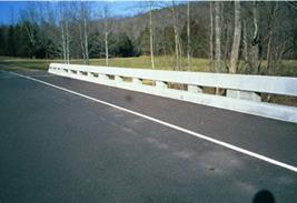 |
| Figure 27. Photo. Barrier type 3—bridge rail.(20) |
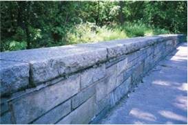 |
| Figure 28. Photo. Second image of barrier type 3—bridge rail.(20) |
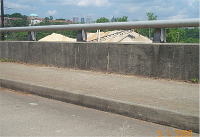 |
| Figure 29. Photo. Third image of barrier type 3—bridge rail.(20) |
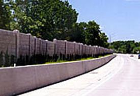 |
| Figure 30. Illustration. Barrier type 4—constant slope barrier.(20) |
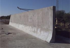 |
| Figure 31. Photo. Barrier type 5 —F-shaped barrier.(20) |
Barrier type 6 is a GM® barrier shape. An image for this barrier shape was not available for the publication but can be viewed with an online search.
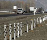 |
| Figure 32. Photo. Barrier type 7— high-tension cable guardrail system.(15) |
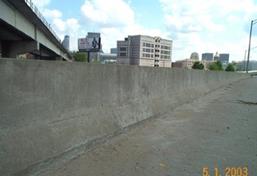 |
| Figure 33. Photo. Barrier type 8— Jersey barrier.(20) |
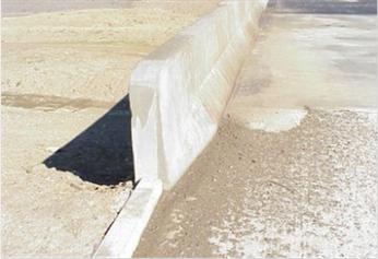 |
| Figure 34. Photo. Second image of barrier type 8 —Jersey barrier.(20) |
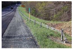 |
| Figure 35. Photo. Barrier type 9—low- tension cable guardrail.(21) |
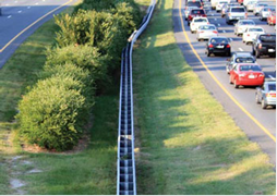 |
| Figure 36. Photo. Barrier type 10 —median barrier steel guardrail.(15) |
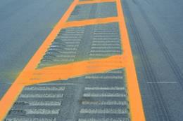 |
| Figure 37. Photo. Barrier type 11—median strip.(22) |
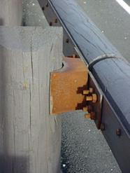 |
| Figure 38. Photo. Barrier type 12—steel-backed timber guardrail.(17) |
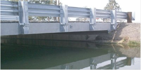 |
| Figure 39. Photo. Barrier type 13—Thrie beam.(20) |
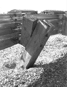 |
| Figure 40. Photo. Barrier type 14—Thrie beam strong post.(16) |
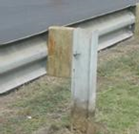 |
| Figure 41. Photo. Barrier type 15—W-beam strong post.(14) |
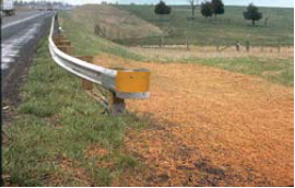 |
| Figure 42. Photo. Barrier type 16— W-beam weak post.(14) |
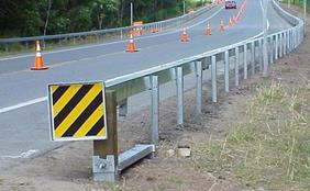 |
| Figure 43. Photo. Barrier type 17—weak post box beam.(23) |
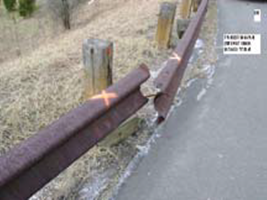 |
| Figure 44. Photo. Barrier type 18— weathering steel (Corten®) guardrail.(14) |
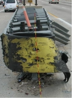 |
| Figure 45. Photo. Barrier type 19—impact attenuator.(4) |
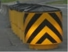 |
| Figure 46. Photo. Second image of barrier type 19—impact attenuator.(4) |
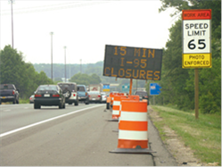 |
| Figure 47. Photo. Third image of barrier type 19—impact attenuator.(24) |
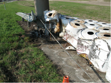 |
| Figure 48. Photo. Fourth image of barrier type 19— impact attenuator.(4) |
Figure 49 through figure 58 present the different types of treatments on the barrier ends that were used as a reference for the variable “barrier end treatment type.” Each treatment corresponds to one attribute in the variable. Other attributes used to describe this variable were outside the road segment of analysis, other, and indistinguishable.
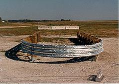 |
| Figure 49. Photo. Barrier end treatment type 1—bull nose end treatment.(25) |
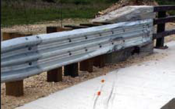 |
| Figure 50. Photo. Barrier end treatment type 2—guardrail bridge attachment.(14) |
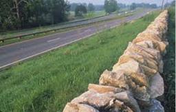 |
| Figure 51. Photo. Barrier end treatment type 3—rock fence.(26) |
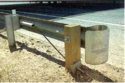 |
| Figure 52. Photo. Barrier end treatment type 4—rounded terminal buffer (“question mark”).(14) |
Barrier end treatment type 5 was SGT (SKT 350) types I, II, and III, HBA. An image for this barrier end treatment was not available for the publication but can be viewed with an online search.
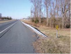 |
| Figure 53. Photo. Barrier end treatment type 6— “turndown” roll-over end section.(14) |
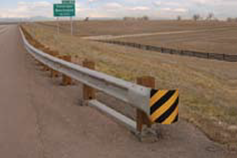 |
| Figure 54. Photo. Barrier end treatment type 7—terminal end sections (boxing glove).(14) |
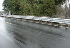 |
| Figure 55. Photo. Barrier end treatment type 8—Thrie beam terminal connector shoe (“end shoe”).(20) |
Barrier end treatment type 9 was a trail end guardrail section. An image for this barrier shape was not available for the publication but can be viewed with an online search.
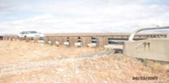 |
| Figure 56. Photo. Barrier end treatment type 10—W-beam terminal connector shoe.(14) |
Barrier end treatment type 11 was a Jersey barrier end treatment type F. An image for this barrier shape was not available for the publication but can be viewed with an online search.
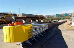 |
| Figure 57. Photo. Barrier end treatment type 12—impact attenuators.(27) |
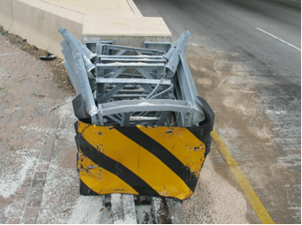 |
| Figure 58. Photo. Barrier end treatment type 12—temporary impact attenuators.(4) |