U.S. Department of Transportation
Federal Highway Administration
1200 New Jersey Avenue, SE
Washington, DC 20590
202-366-4000


Skip to content
Facebook iconYouTube iconTwitter iconFlickr iconLinkedInInstagram

Federal Highway Administration Research and Technology
Coordinating, Developing, and Delivering Highway Transportation Innovations

 
REPORT
This report is an archived publication and may contain dated technical, contact, and link information
Back to Publication List        
Publication Number:  FHWA-HRT-17-048    Date:  May 2018
Publication Number: FHWA-HRT-17-048
Date: May 2018


Enhancing Safety and Operations at Complex Interchanges With Improved Signing, Markings, and Integrated Geometry

Appendix B. Diagrams of Layouts With Signing Alternatives (Supplement to Chapter 6)

Introduction

This appendix provides a complete catalog of the signing alternatives (e.g., A, C, L, and E) used for testing in the simulator, in conjunction with diagrams of the geometric layouts associated with each. Each signing alternative was designed to accommodate the three possible destinations for each of the alternatives in a given layout. These movements are considered THRU (T), LEFT (L), and RIGHT (R). Participants were told that their task was to follow the signs toward Greenville; Greenville was always the destination to which they were instructed to drive. For example, a participant might be trying to navigate to Greenville on Route 28 without being told a cardinal direction for Route 28. Using the information provided on overhead guide signs, the participant would either continue THRU to Greenville or exit the interchange to the RIGHT or the LEFT toward Greenville based on the experimental scenario. As there is no LEFT movement in Layout A, a Destination of “L” for this layout represents the second RIGHT movement.

Additional information on this project’s research design can be found in chapter 6.

SCENARIOS FOR LAYOUT A

LAYOUT A
ALTERNATIVE A1, SCENARIO A1-L

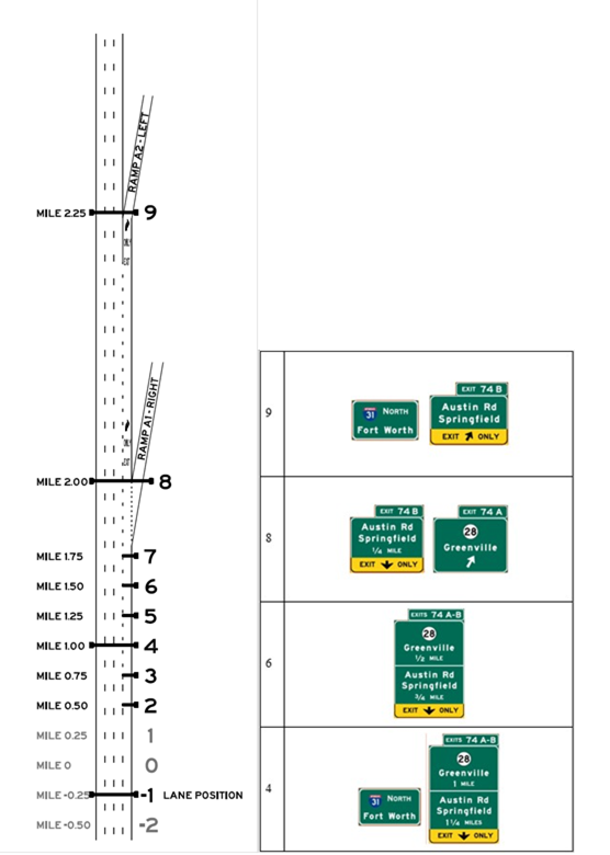
Layout A, Alternative A1, Scenario A1-L. Graphics. The graphic shows an image of interchange layout A on the left, and an image of signing alternative A1-L on the right. Interchange layout A includes an upstream exit followed by a mandatory exit, and uses starting lanes 3 or 4. Signing alternative A1-L is designed so that the target destination is followed by taking the second ramp (the mandatory exit).

LAYOUT A
ALTERNATIVE A1, SCENARIO A1-R

Layout A, Alternative A1, Scenario A1-R. Graphics. The graphic shows an image of interchange layout A on the left, and an image of signing alternative A1-R on the right. Interchange layout A includes an upstream exit followed by a mandatory exit, and uses starting lanes 3 or 4. Signing alternative A1-R is designed so that the target destination is followed by taking the first ramp (the upstream exit).

LAYOUT A
ALTERNATIVE A1, SCENARIO A1-T

Layout A, Alternative A1, Scenario A1-T. Graphics. The graphic shows an image of interchange layout A on the left, and an image of signing alternative A1-T on the right. Interchange layout A includes an upstream exit followed by a mandatory exit, and uses starting lanes 3 or 4. Signing alternative A1-T is designed so that the target destination is followed by continuing through on the mainline.

LAYOUT A
ALTERNATIVE A2, SCENARIO A2-L

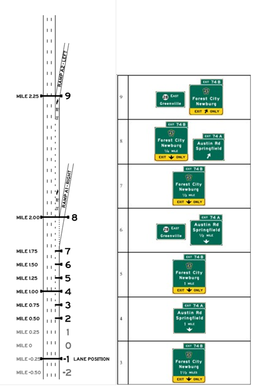
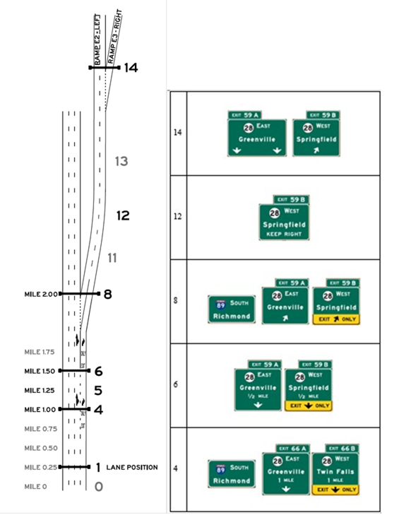
Layout A, Alternative A2, Scenario A2-L. Graphics. The graphic shows an image of interchange layout A on the left, and an image of signing alternative A2-L on the right. Interchange layout A includes an upstream exit followed by a mandatory exit, and uses starting lanes 3 or 4. Signing alternative A2-L is designed so that the target destination is followed by taking the second ramp (the mandatory exit).

LAYOUT A
ALTERNATIVE A2, SCENARIO A2-R

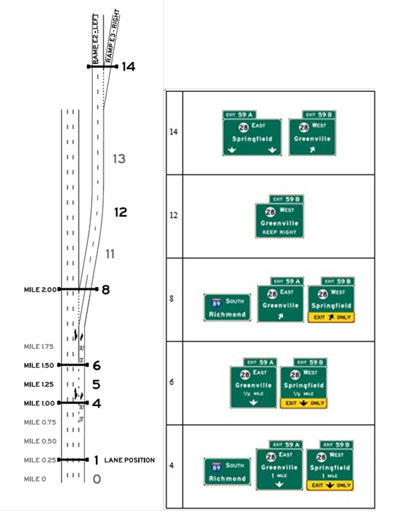
Layout A, Alternative A2, Scenario A2-R. Graphics. The graphic shows an image of interchange layout A on the left, and an image of signing alternative A2-R on the right. Interchange layout A includes an upstream exit followed by a mandatory exit, and uses starting lanes 3 or 4. Signing alternative A2-R is designed so that the target destination is followed by taking the first ramp (the upstream exit).

LAYOUT A
ALTERNATIVE A2, SCENARIO A2-T

Layout A, Alternative A2, Scenario A2-T. Graphics. The graphic shows an image of interchange layout A on the left, and an image of signing alternative A2-T on the right. Interchange layout A includes an upstream exit followed by a mandatory exit, and uses starting lanes 3 or 4. Signing alternative A2-T is designed so that the target destination is followed by continuing through on the mainline.

LAYOUT A
ALTERNATIVE A3, SCENARIO A3-L

Layout A, Alternative A3, Scenario A3-L. Graphics. The graphic shows an image of interchange layout A on the left, and an image of signing alternative A3-L on the right. Interchange layout A includes an upstream exit followed by a mandatory exit, and uses starting lanes 3 or 4. Signing alternative A3-L is designed so that the target destination is followed by taking the second ramp (the mandatory exit).

LAYOUT A
ALTERNATIVE A3, SCENARIO A3-R

Layout A, Alternative A3, Scenario A3-R. Graphics. The graphic shows an image of interchange layout A on the left, and an image of signing alternative A3-R on the right. Interchange layout A includes an upstream exit followed by a mandatory exit, and uses starting lanes 3 or 4. Signing alternative A3-R is designed so that the target destination is followed by taking the first ramp (the upstream exit).

LAYOUT A
ALTERNATIVE A3, SCENARIO A3-T

Layout A, Alternative A3, Scenario A3-T. Graphics. The graphic shows an image of interchange layout A on the left, and an image of signing alternative A3-T on the right. Interchange layout A includes an upstream exit followed by a mandatory exit, and uses starting lanes 3 or 4. Signing alternative A3-T is designed so that the target destination is followed by continuing through on the mainline.

SCENARIOS FOR LAYOUT C

LAYOUT C
ALTERNATIVE C1, SCENARIO C1-L

Layout C, Alternative C1, Scenario C1-L. Graphics. The graphic shows an image of interchange layout C on the left, and an image of signing alternative C1-L on the right. Interchange layout C includes an option lane exit and a downstream split, and uses starting lanes 2, 3 or 4. Signing alternative C1-L is designed so that the target destination is followed by remaining through at the downstream split.

LAYOUT C
ALTERNATIVE C1, SCENARIO C1-R

Layout C, Alternative C1, Scenario C1-R. Graphics. The graphic shows an image of interchange layout C on the left, and an image of signing alternative C1-R on the right. Interchange layout C includes an option lane exit and a downstream split, and uses starting lanes 2, 3 or 4. Signing alternative C1-R is designed so that the target destination is followed by taking the exit to the right at the downstream split.

LAYOUT C
ALTERNATIVE C1, SCENARIO C1-T

Layout C, Alternative C1, Scenario C1-T. Graphics. The graphic shows an image of interchange layout C on the left, and an image of signing alternative C1-T on the right. Interchange layout C includes an option lane exit and a downstream split, and uses starting lanes 2, 3 or 4. Signing alternative C1-T is designed so that the target destination is followed by continuing through on the mainline.

LAYOUT C
ALTERNATIVE C2, SCENARIO C2-L

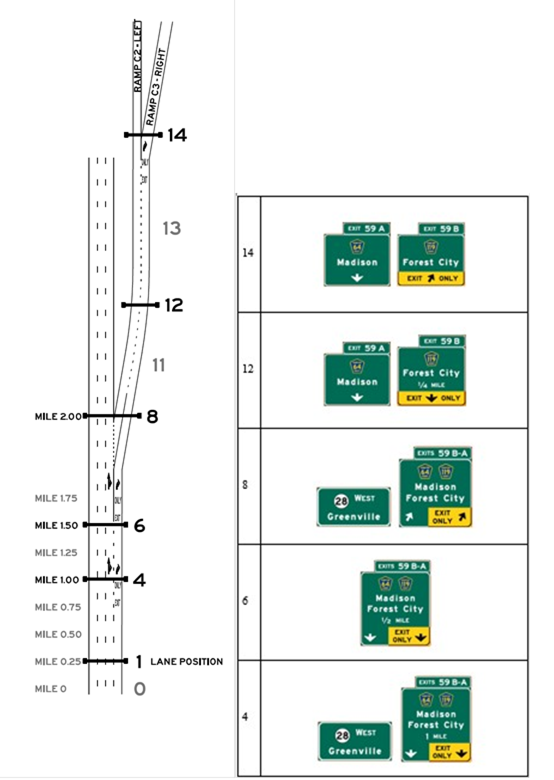
Layout C, Alternative C2, Scenario C2-L. Graphics. The graphic shows an image of interchange layout C on the left, and an image of signing alternative C2-L on the right. Interchange layout C includes an option lane exit and a downstream split, and uses starting lanes 2, 3 or 4. Signing alternative C2-L is designed so that the target destination is followed by remaining through at the downstream split.

LAYOUT C
ALTERNATIVE C2, SCENARIO C2-R

Layout C, Alternative C2, Scenario C2-R. Graphics. The graphic shows an image of interchange layout C on the left, and an image of signing alternative C2-R on the right. Interchange layout C includes an option lane exit and a downstream split, and uses starting lanes 2, 3 or 4. Signing alternative C2-R is designed so that the target destination is followed by taking the exit to the right at the downstream split.

LAYOUT C
ALTERNATIVE C2, SCENARIO C2-T

Layout C, Alternative C2, Scenario C2-T. Graphics. The graphic shows an image of interchange layout C on the left, and an image of signing alternative C2-T on the right. Interchange layout C includes an option lane exit and a downstream split, and uses starting lanes 2, 3 or 4. Signing alternative C2-T is designed so that the target destination is followed by continuing through on the mainline.

LAYOUT C
ALTERNATIVE C3, SCENARIO C3-L

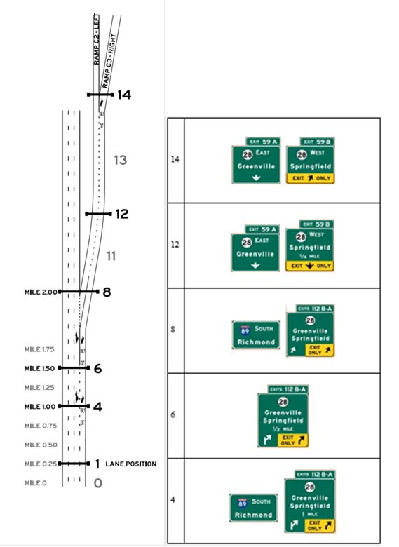
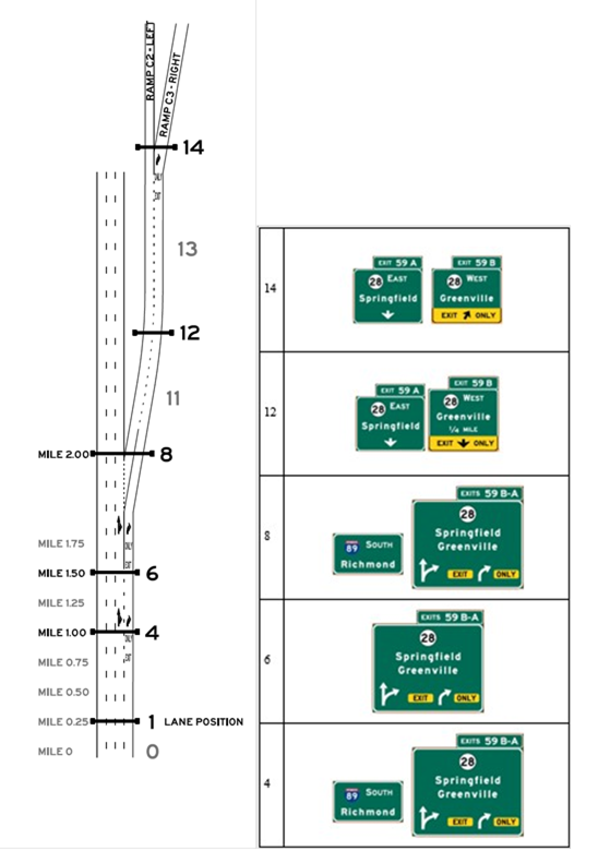
Layout C, Alternative C3, Scenario C3-L. Graphics. The graphic shows an image of interchange layout C on the left, and an image of signing alternative C3-L on the right. Interchange layout C includes an option lane exit and a downstream split, and uses starting lanes 2, 3 or 4. Signing alternative C3-L is designed so that the target destination is followed by remaining through at the downstream split.

LAYOUT C
ALTERNATIVE C3, SCENARIO C3-R

Layout C, Alternative C3, Scenario C3-R. Graphics. The graphic shows an image of interchange layout C on the left, and an image of signing alternative C3-R on the right. Interchange layout C includes an option lane exit and a downstream split, and uses starting lanes 2, 3 or 4. Signing alternative C3-R is designed so that the target destination is followed by taking the exit to the right at the downstream split.

LAYOUT C
ALTERNATIVE C3, SCENARIO C3-T

Layout C, Alternative C3, Scenario C3-T. Graphics. The graphic shows an image of interchange layout C on the left, and an image of signing alternative C3-T on the right. Interchange layout C includes an option lane exit and a downstream split, and uses starting lanes 2, 3 or 4. Signing alternative C3-T is designed so that the target destination is followed by continuing through on the mainline.

LAYOUT C
ALTERNATIVE C4, SCENARIO C4-L

Layout C, Alternative C4, Scenario C4-L. Graphics. The graphic shows an image of interchange layout C on the left, and an image of signing alternative C4-L on the right. Interchange layout C includes an option lane exit and a downstream split, and uses starting lanes 2, 3 or 4. Signing alternative C4-L is designed so that the target destination is followed by remaining through at the downstream split.

LAYOUT C
ALTERNATIVE C4, SCENARIO C4-R

Layout C, Alternative C4, Scenario C4-R. Graphics. The graphic shows an image of interchange layout C on the left, and an image of signing alternative C4-R on the right. Interchange layout C includes an option lane exit and a downstream split, and uses starting lanes 2, 3 or 4. Signing alternative C4-R is designed so that the target destination is followed by taking the exit to the right at the downstream split.

LAYOUT C
ALTERNATIVE C4, SCENARIO C4-T

Layout C, Alternative C4, Scenario C4-T. Graphics. The graphic shows an image of interchange layout C on the left, and an image of signing alternative C4-T on the right. Interchange layout C includes an option lane exit and a downstream split, and uses starting lanes 2, 3 or 4. Signing alternative C4-T is designed so that the target destination is followed by continuing through on the mainline.

SCENARIOS FOR LAYOUT E

LAYOUT E
ALTERNATIVE E1, SCENARIO E1-L

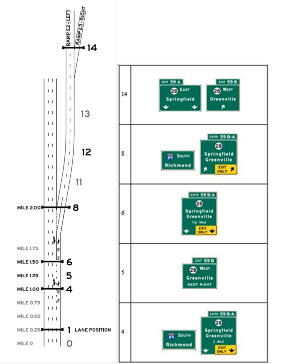
Layout E, Alternative E1, Scenario E1-L. Graphics. The graphic shows an image of interchange layout E on the left, and an image of signing alternative E1-L on the right. Interchange layout E includes an option lane exit and a downstream exit, and uses starting lanes 2, 3 or 4. Signing alternative E1-L is designed so that the target destination is followed by remaining through after taking the first (option lane) exit.

LAYOUT E
ALTERNATIVE E1, SCENARIO E1-R

Layout E, Alternative E1, Scenario E1-R. Graphics. The graphic shows an image of interchange layout E on the left, and an image of signing alternative E1-R on the right. Interchange layout E includes an option lane exit and a downstream exit, and uses starting lanes 2, 3 or 4. Signing alternative E1-R is designed so that the target destination is followed by taking the downstream exit.

LAYOUT E
ALTERNATIVE E1, SCENARIO E1-T

Layout E, Alternative E1, Scenario E1-T. Graphics. The graphic shows an image of interchange layout E on the left, and an image of signing alternative E1-T on the right. Interchange layout E includes an option lane exit and a downstream exit, and uses starting lanes 2, 3 or 4. Signing alternative E1-T is designed so that the target destination is followed by continuing through on the mainline.

LAYOUT E
ALTERNATIVE E2, SCENARIO E2-L

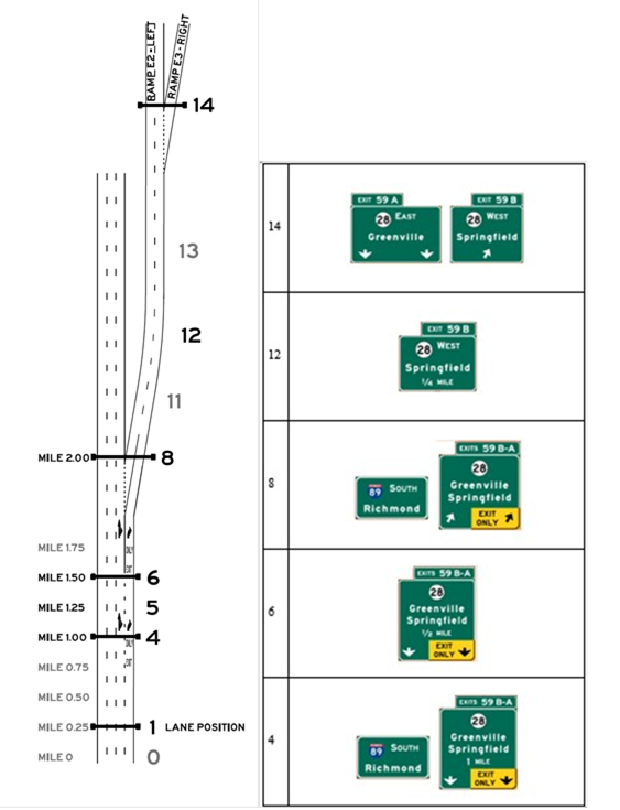
Layout E, Alternative E2, Scenario E2-L. Graphics. The graphic shows an image of interchange layout E on the left, and an image of signing alternative E2-L on the right. Interchange layout E includes an option lane exit and a downstream exit, and uses starting lanes 2, 3 or 4. Signing alternative E2-L is designed so that the target destination is followed by remaining through after taking the first (option lane) exit.

LAYOUT E
ALTERNATIVE E2, SCENARIO E2-R

Layout E, Alternative E2, Scenario E2-R. Graphics. The graphic shows an image of interchange layout E on the left, and an image of signing alternative E2-R on the right. Interchange layout E includes an option lane exit and a downstream exit, and uses starting lanes 2, 3 or 4. Signing alternative E2-R is designed so that the target destination is followed by taking the downstream exit.

LAYOUT E
ALTERNATIVE E2, SCENARIO E2-T

Layout E, Alternative E2, Scenario E2-T. Graphics. The graphic shows an image of interchange layout E on the left, and an image of signing alternative E2-T on the right. Interchange layout E includes an option lane exit and a downstream exit, and uses starting lanes 2, 3 or 4. Signing alternative E2-T is designed so that the target destination is followed by continuing through on the mainline.

LAYOUT E
ALTERNATIVE E3, SCENARIO E3-L

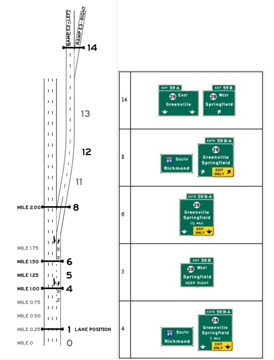
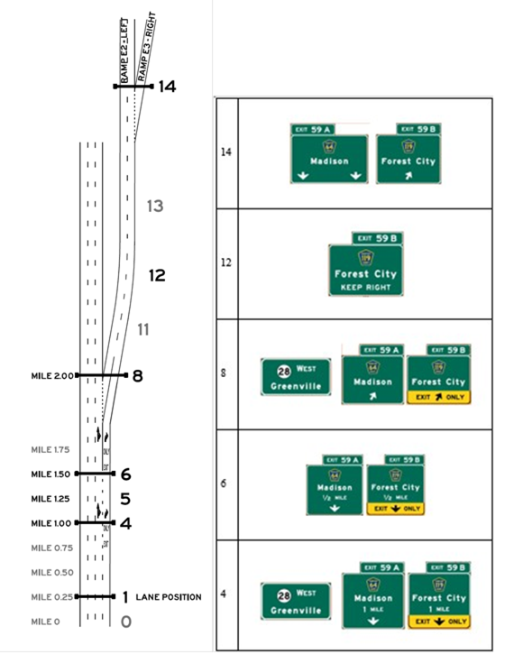
Layout E, Alternative E3, Scenario E3-L. Graphics. The graphic shows an image of interchange layout E on the left, and an image of signing alternative E3-L on the right. Interchange layout E includes an option lane exit and a downstream exit, and uses starting lanes 2, 3 or 4. Signing alternative E3-L is designed so that the target destination is followed by remaining through after taking the first (option lane) exit.

LAYOUT E
ALTERNATIVE E3, SCENARIO E3-R

Layout E, Alternative E3, Scenario E3-R. Graphics. The graphic shows an image of interchange layout E on the left, and an image of signing alternative E3-R on the right. Interchange layout E includes an option lane exit and a downstream exit, and uses starting lanes 2, 3 or 4. Signing alternative E3-R is designed so that the target destination is followed by taking the downstream exit.

LAYOUT E
ALTERNATIVE E3, SCENARIO E3-T

Layout E, Alternative E3, Scenario E3-T. Graphics. The graphic shows an image of interchange layout E on the left, and an image of signing alternative E3-T on the right. Interchange layout E includes an option lane exit and a downstream exit, and uses starting lanes 2, 3 or 4. Signing alternative E3-T is designed so that the target destination is followed by continuing through on the mainline.

SCENARIOS FOR LAYOUT L

LAYOUT L
ALTERNATIVE L1, SCENARIO L1-L

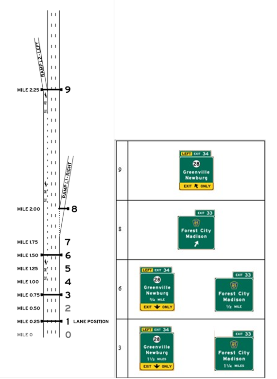
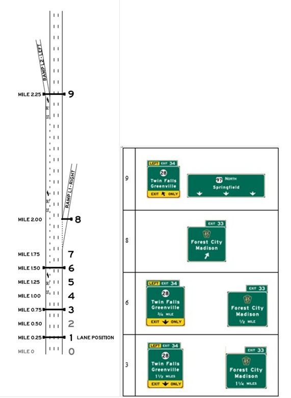
Layout L, Alternative L1, Scenario L1-L. Graphics. The graphic shows an image of interchange layout L on the left, and an image of signing alternative L1-L on the right. Interchange layout L includes an upstream exit and a left mandatory exit, and uses starting lanes 1 or 3. Signing alternative L1-L is designed so that the target destination is followed by taking the left exit.

LAYOUT L
ALTERNATIVE L2, SCENARIO L2-L

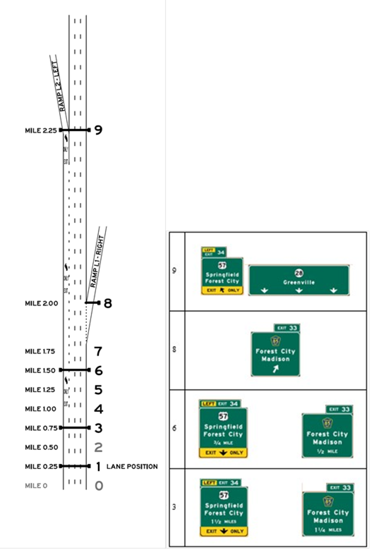
Layout L, Alternative L2, Scenario L2-L. Graphics. The graphic shows an image of interchange layout L on the left, and an image of signing alternative L2-L on the right. Interchange layout L includes an upstream exit and a left mandatory exit, and uses starting lanes 1 or 3. Signing alternative L2-L is designed so that the target destination is followed by taking the left exit.

LAYOUT L
ALTERNATIVE L2, SCENARIO L2-T

Layout L, Alternative L2, Scenario L2-T. Graphics. The graphic shows an image of interchange layout L on the left, and an image of signing alternative L2-T on the right. Interchange layout L includes an upstream exit and a left mandatory exit, and uses starting lanes 1 or 3. Signing alternative L2-T is designed so that the target destination is followed by remaining through on the mainline.
Federal Highway Administration | 1200 New Jersey Avenue, SE | Washington, DC 20590 | 202-366-4000
Turner-Fairbank Highway Research Center | 6300 Georgetown Pike | McLean, VA | 22101